Radiological techniques, protocols and basics of interpretation in head of neck imaging
3.1: Radiological techniques, protocols and basics of interpretation in head of neck imaging
V. Saritha
Conventional radiography
Introduction
X-ray is easily available and economical. Most of clinical indications are based on its easy availability even though the anatomical details provided are poor compared with the cross-sectional imaging modalities. Conventional radiography is unreliable when used alone and has a high chance of misdiagnosis. Now most of the clinical questions are answered by the commonly used cross-sectional imaging modalities. However, X-ray of skull, PNS and OPG is still used in certain circumstances as the initial screening tool.
Indications for X-ray skull and PNS
1. Screening tool for head and neck trauma especially in paediatric population.
2. Infections such as osteomyelitis usually secondary to sinusitis.
3. Suspected skull lesions to give an idea regarding the plane of the lesion and to decide the need of cross-sectional imaging.
4. To assess the surgically implanted material such as shunts, cochlear implants, intrathecal catheters, orthopaedic fixators and deep brain stimulators.
5. Shunt series radiographs are used to determine the position of the shunt components and are obtained in at least two planes. These images are helpful in determining the type of shunt, the localization of the proximal and distal catheter tips and the cause of shunt dysfunction.
6. Commonly used in the skeletal survey for suspected child abuse, metastatic workup, metabolic bone disorder, multiple myeloma, skeletal dysplasias, LCH and Paget’s disease.
7. Evaluation of CVJ anomalies.
8. Evaluation of abnormal size and shape of skull.
9. X-ray PNS is commonly used for suspected cases of sinusitis and its complications.
10. Dedicated views for mastoid in suspected cases of mastoiditis, CSOM, etc.
11. X-ray of TMJ is used for TMJ arthritis, trauma, dislocation, etc.
Indications of OPG are discussed separately later in this chapter.
Commonly used views
1. Skull lateral supine
2. Skull lateral standing/erect
3. Skull AP frontooccipital view
4. Skull AP frontooccipital view 30 degrees caudad (Towne’s view)
5. Skull PA occipitofrontal view
6. Skull PA occipitofrontal 15 degrees caudad (Caldwell’s view)
7. Skull PA axial HASS method
8. Submentovertical view (basilar view)
9. Verticosubmental projection
10. Occipitomental view (Water’s view)
11. Nasal bones
12. X-ray mandible
General overview
• Skull radiographs can be taken with an isocentric skull unit or with an ordinary bucky. It can also be done with a stationary grid and tube. The image quality of isocentric skull unit is considered the best of all the other techniques.
• Patient should be educated to hold breath and not to move during the procedure.
• All the radioopaque objects including hair clips, earrings and dentures should be removed to avoid artefacts.
• Mean effective dose of skull X-ray is 0.1 mSV.
• kVp of 70–85 kV and 20–40 mAs is generally used for skull X-rays.
• Source image distance is around 40 inches (around 100 cm).
• If grid is used, 10:1 stationary grid is used.
• 24 × 30 cm(10 × 12 film) cassettes are usually used for plain skull radiology.
1. Lateral view – supine:
• Position of the patient – The patient is in supine position. Head of the patient is rotated so that interorbital plane is perpendicular to the bucky and midsagittal plane is parallel to the bucky. The side of interest should be closer to the cassette.
• Cassette should be positioned transversely in the bucky so that upper border is around 5 cm above the vertex.
• Central ray should pass midway between glabella and external occipital protuberance around 5 cm above the external auditory meatus. The central ray is horizontal; no angulation is given.
2. Lateral view erect:
• Position of the patient – The patient is in standing position; median sagittal plane is parallel to the bucky and the interorbital plane is perpendicular to it. The side of interest should be closer to the cassette.
• The cassette is positioned transversely in the bucky such that its upper border is 5 cm above the vertex of skull.
• No angulation is given to the central ray. Central ray should pass midway between glabella and external occipital protuberance around 5 cm above the external auditory meatus. The central ray is horizontal.
Essential image characteristics of lateral view skull:
1. The clinoid process of sella turcica, floors of anterior and posterior cranial fossa should be superimposed, i.e. true lateral projection should be obtained.
2. All the cranial bones and C1 should also be included in the image.
3. Frontooccipital view (AP view):
• The frontooccipital projections are carried out only when the patient is not able to move and the imaging has to be done in supine position. The anatomical details provided by frontooccipital view are same as that of occipitofrontal view.
• Position of the patient – The patient lies supine with orbitomeatal baseline perpendicular to the cassette.
• Head should be kept straight so that median sagittal plane is perpendicular to the film.
• Central ray passes along the midsagittal plane and through the nasion.
• The petrous ridges will be projected within the orbit in its upper one-third modifications of this view with varying degrees of caudal angulation 10, 15 and 20 degrees.
4. Occipitofrontal view (PA view):
• Patient position – The patient is in sitting position facing the bucky with the midsagittal plane perpendicular to the bucky. Images can be taken with the patient in prone position also.
Nose and forehead should be touching the bucky, with neck flexed so that the orbitomeatal line is perpendicular to the bucky.
• The central ray passes through the nasion in the midsagittal plane perpendicular to the bucky. No angulation is given.
Essential image characteristics of AP and PA view – The image should be nonrotated including all the cranial bones and skull margins in the image.
• Position of the patient – The patient lies supine with orbitomeatal baseline perpendicular to the cassette.
• Central ray is angled caudally so that it makes an angle of 30 degrees to the orbitomeatal plane.
• The centering should be such that the ray passes approximately 5 cm above the glabella midway between the external auditory meatuses.
• Image characteristics – (1) Sella turcica should be seen within the foramen magnum and in the midline. Petrous ridges should be symmetrical on either side. (2) The entire occipital bone, posterior portion of parietal bone and lambdoid suture should be clearly demonstrated.
• Advantage of Towne’s view – Nonangulated AP view will have skull base and facial bone overlap; hence, in angulated view, occipital bone and posterior fossa can be better evaluated.
6. Occipitofrontal 15 degrees caudad PA (Caldwell’s view):
• The positioning of the patient is same as occipitofrontal view. But the tube is angulated 15 degrees caudad to the orbitomeatal baseline. PA projection.
• Central ray passes through the vertex and exits at the nasion.
• Advantage of Caldwell’s view – This modification is designed for better visualization of paranasal sinus especially the frontal sinus.
• Image characteristics – Nonrotated image with petrous ridges projected over the lower one-third of orbit. The tube angulation may be increased further to 30 degrees caudad so that inferior orbital rim is better visualized. Petrous pyramids will be projected below the inferior orbital rim on the 30-degree angulation.
7. PA axial projection (HASS method):
• This is an alternative projection to the half axial Towns view.
• Position of the patient – The patient’s nose/forehead should touch the bucky. OML should be perpendicular to the cassette.
• Central ray should be directed 25 degrees cephalad to OML.
• The central ray should be in the midsagittal plane at the level of external auditory meatus and should exit around 4 cm above the nasion.
• Essential image characteristics – (1) Occipital bone, petrous pyramids and foramen magnum should be well seen in the image with no rotation. Bilateral petrous ridges should be symmetrical. (2) Posterior clinoid and dorsum sella should be visible through the foramen magnum.
• Position of the patient – The patient’s neck is hyperextended with vertex touching the cassette. Midsagittal plane is perpendicular to the cassette.
• Orbitomeatal line should be as close to the cassette as possible and parallel to it. Imaging can be done in spine position or erect position.
• Central ray should be perpendicular to the orbitomeatal line and should pass around 4 cm inferior to the symphysis menti midway between the external auditory meatuses.
• Image characteristics – (1) The angle of mandible should be projected away from the petrous temporal bone on either side. (2) The foramina of middle cranial fossa should be symmetrical and well seen on either side of midline.
9. Verticosubmental view:
• It is an alternative to visualize the skull base instead of the routine submentovertical view.
• Position of the patient – The patient is in prone position. Chin should touch the table. Neck extended. Midsagittal plane is perpendicular to the cassette, and arms are kept on the sides.
• Central ray will be perpendicular to infraorbitomeatal line passing through the sella, directed between the angles of mandible, 3/4th inch anterior to the external auditory meatus.
• Essential image characteristics – (1) no rotation, (2) cranial base and sphenoid sinus are well demonstrated.
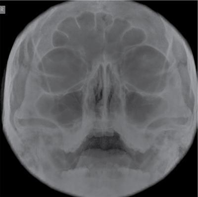
10. Occipitomental view (Water’s view):
• It is a PA radiograph with angulation.
• The patient is facing the bucky with chin in contact with the bucky.
• Mentomeatal line should be perpendicular to the film. Orbitomeatal line should be around 35–40 degrees to the bucky.
• Central ray should be perpendicular to the bucky and exit at the acanthion. In this position, the cross lines at the bucky will coincide with the patient’s anterior nasal spine.
• The patient’s mouth is kept closed for frontal and maxillary sinus. The patient’s mouth has to be kept open to visualize the sphenoid sinus.
• Image characteristics – The petrous ridges on both sides should appear below the floor of maxillary sinus on both sides and without rotation.
• Modified mentooccipital view (AP projection) can be taken if the patient who has sustained trauma and present supine.
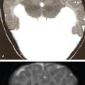
• Usually done for acute sinusitis and in case of trauma to assess the facial bones (Figs. 3.1.1 and 3.1.2).
11. X-ray mandible:
Lateral 30 Degrees Caudad
• Position of the patient – The patient lies in supine position. Median sagittal plane is parallel to the cassette, and interpupillary line is perpendicular to the cassette.
• Central ray is angled 30 degrees cranially and is centered 5 cm below the angle of mandible away from the cassette.
• Whole of the mandible and TMJ to be included in the collimation field.
• Essential image characteristics – (1)Whole of the mandible should be included in the image. (2) The mandible on either side should not be superimposed.
Mandible: Posteroanterior
• Position of the patient – The patient will be facing the bucky. Median sagittal plane and orbitomeatal baseline should be in the midline and perpendicular to the bucky.
• The central ray should pass midway between the cassette, centered in the midline between the angles of mandible.
• Essential image characteristics – There should be no rotation, and whole of the mandible must be included in the image.
12. Nasal bone lateral:
• Position of the patient – Head is turned so that median sagittal plane is parallel to the cassette and interpupillary line perpendicular to the cassette.
• The central ray should pass through the centre of the nasal bones.
• This projection is avoided in most circumstances due to increased radiation dose to eyes.
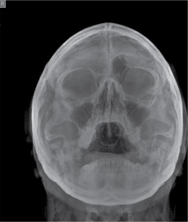
Fig. 3.1.2X-ray PNS Water’s view with mouth open demonstrating sphenoid sinus.
Other views
1. Temporomandibular joint:
AP Axial Projection
• Neck of the patient is flexed with OML perpendicular to the cassette.
• Central ray should pass midway between the temporomandibular joints 7.5 cm above the nasion.
Lateral 25 degrees caudad:
• Head is rotated so that side of the head comes in contact with the cassette.
• The central ray is angulated 25 degrees caudad and centered to a point 5 cm above the TMJ, so that closer to the cassette the central ray passes through the joint.
2. Petrous portion of temporal bone (Stenver’s view):
• Anterior oblique view.
• The middle part of supraorbital margin on the ipsilateral side is centered to the middle of the bucky. Nose and forehead should be in contact with the table and orbitomeatal line at 90 degrees to the table.
• Centering should be between the external occipital protuberance and external auditory meatus. A 12 degree cephalad angulation is used.
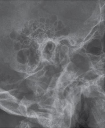
3. Mastoid – lateral oblique view:
• Head is rotated so that the median sagittal plane is parallel to the bucky.
• Central ray is passing 5 cm above and 2.5 cm behind the external auditory meats away from the cassette. A caudal angulation of approximately 25 degrees is given (Fig. 3.1.3).
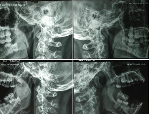
• Lateral view, central ray is angulated 25 degrees caudad.
• The centering should be 5 cm superior to the joint away from the cassette so that the ray passes through the cassette near the joint.
• Open mouth and closed mouth view is taken (Fig. 3.1.4).
Fig. 3.1.3X-ray of mastoids demonstrating mastoid air cells, EAM and TMJ.
Fig. 3.1.4X-ray demonstrating TMJ in open mouth and closed mouth positions on the right and left sides.
Rhese method – technique used for orbits, parietoorbital oblique projection.
Normal variants in plain X-ray skull
1. Normal intracranial calcifications such as pineal gland calcification, choroid plexus calcification, dural calcification, basal ganglia calcification, habenular calcification, calcification of ligaments such as stylohyoid ligament.
2. Lacunar skull – This appearance is due to areas of calvarial thinning typically seen in infants. This usually resolves in few years.
3. Hyperostosis frontalis interna – Seen as thickening of inner table of the frontal bone. Typically seen in middle-aged women.
4. Varying degrees of pneumatization in PNS and mastoid – A common finding is frontal sinus hypoplasia, which should not be mistaken for sinusitis.
5. Pacchionian granulations – Seen as well-defined circular erosions in the inner table of skull. They are arachnoid granulations and are typically seen along the parasagittal location. Usually small in size but can appear larger at times.
6. Parietal foramina – Bilateral symmetric parasagittal bone defects posteriorly. This usually results from delayed and incomplete ossification of parietal bone.
7. Wormian bones – Small bones seen within the sutures.
8. Radiolucency may be seen in the skull corresponding to dural venous sinus and emissary veins.
Some of the common pathologic appearances plain X-ray skull
2. Focal sclerotic lesions of skull – FD, calvarial metastasis, osteoma, etc.
3. Focal lytic lesions of skull – multiple myeloma, metastasis, sarcoidosis, eosinophilic granuloma, hyperparathyroidism, etc.
4. Abnormal shape of calvarium – craniosynostosis, microcephaly, macrocephaly, hydrocephalus, etc.
5. Generalized increase in the density of skull bone – osteopetrosis.
6. Generalized decrease in density of skull bone – osteogenesis imperfecta.
Common abnormal appearance in X-ray PNS
1. Air fluid level in the sinus indicates acute sinusitis.
2. Opacification of the sinus could be due to polyp, mass lesion or sinusitis.
3. Thickening of mucosa (well seen in the lateral wall) with sclerosis of bone is indicative of chronic sinusitis.
4. Mucocele of the sinus will be seen as expansion of the sinus with loss of normal scalloping.
Orthopantomogram
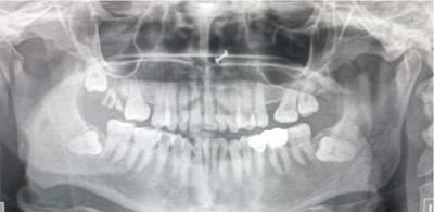
• The orthopantomogram is widely used in dental practice. It is a panoramic single image radiograph including the mandible, maxilla and teeth.
• Indications:
1. Trauma
2. To evaluate unerupted tooth
3. To evaluate the nature and extend of jaw lesions such as cysts, neoplasms, other bone pathologies such as fibrous dysplasia and Paget’s disease
4. TMJ pathologies
5. When intraoral radiography is not possible, e.g. trismus
6. Assessment for placement of dental implants
Though OPG does not provide fine anatomical details as intraoral X-rays, it gives the overall anatomy of mandible, maxilla, temporomandibular joints, visualized surrounding structures such as maxillary sinus, hard palate, nasal fossa, etc.
Principles of OPG
• During an OPG, the patient remains in a stationary position (seated or standing).
• Both the X-ray source and film rotate in combination around the patient simultaneously.
• The X-ray source rotates from one side of the jaw and then to the other side of the jaw.
• The film rotates opposite to the X-ray source.
• The X-ray source moves in front of the patient, and the film rotates behind the patient.
• Vertical X-ray beam with slit collimation is used. The beam is given around 8 degree upward inclination. Corresponding metal collimators in front of film cassette will allow small part of the film to be exposed each time. Throughout the exposure, different part of the film will be exposed.
• This results in formation of an image layer in form of dental arch called the focal trough.
Procedure
• All radioopaque objects in the head and neck should be removed including jewellery, intraoral devices, etc.
• Patient’s back should be kept straight. Ask the patient to bite the block, andtooth must be kept at the groove in the bite block.
• Midsagittal plane is perpendicular to the floor. Frankfort horizontal plane (plane of superior border of external auditory meatus to infraorbital rim) should be parallel to the floor.
• The patient has to keep the lips closed, and tongue has to be kept pressed to the roof of the mouth.
• Check the symmetry of the position before exposure, and the patient has to be explained to stay still during exposure.
Disadvantages
1. Image may not be sharp due to magnification variation and tomographic blur and overlap of adjacent teeth.
2. Superimposition of adjacent soft tissue (Fig. 3.1.5).
Fig. 3.1.5Orthopantomogram images demonstrating the mandible, maxilla and teeth.
Some obsolete procedures in skull radiography
• Pneumoencephalography – Relatively invasive investigation. It involves replacing the cerebrospinal fluid (CSF) with air, and further X-rays are taken to visualize the intracranial structures.
• CP angle myelography or posterior fossa myelography – After lumbar puncture, iodinated contrast material was instilled. Then the patient is kept in prone position; further, the fluoroscopy table is tilted so the contrast material reaches the posterior fossa.
• Temporal bone tomography – Tomographic units acquired thin sections to evaluate the complex anatomy of the temporal bone. Now it is completely replaced by HRCT.
Contrast studies
Barium pharyngogram
Indications – Lesions below the cricopharyngeus cannot be seen with a laryngeal mirror; hence, barium swallow is very useful for such cases and helps to identify both functional and structural abnormalities:
• common indication is dysphagia;
• congenital lesions such as diverticula;
• focal mass lesions both benign and malignant lesions;
• postlaryngectomy patients to look for fistula;
• postsurgical patients to look for stenosis which may suggest recurrence; and
• disorders of swallowing.
Contrast media used – High-density barium is used in routine cases. Water-soluble contrast medium is used in case of suspected perforation (gastrografin is used). In suspected cases of aspiration, low osmolar contrast medium is used.
Patient preparation – The pharyngeal surface has to be dry for better barium coating (hence the patient should be fasting for at least 4 hours).
Procedure
• The patient is made to swallow thick barium, and spot images are taken.
• The pharynx and upper oesophagus is normally examined in the lateral and AP projections with the patient standing. High KV technique is used.
• Delayed images are taken to assess emptying of barium.
• A slightly oblique lateral projection is to be taken for better visualization of upper cervical esophaus. Head may be slightly tilted so that the mandible is projected over the occiput.
• The lateral images are recorded first as it is more important. Video or cine recordings are made with fluoroscopy. The cones adjusted so that bolus movements can be well seen.
• Structural lesions are best images using air contrast technique. A well-collimated lateral view in modified Valsalva manoeuvre is taken (the patient is asked to puff out the cheeks as if blowing a trumpet). Second lateral view is taken while the patient is phonating the letter E. Anteroposterior views are also taken with the patient performing the same manoeuvres.
Normal appearance
Anteroposterior images of the pharynx – Contrast will be seen filling the vallecula and is seen as symmetric structures on either side of median glossoepiglottic fold. Below that at the hypopharynx, there is piriform sinus and postcricoid area. The lateral walls of the piriform sinuses correspond to the lateral margins of the hypopharynx. The entire bulk of larynx presses on the pharynx to form a coated mucosal surface called the postcricoid line. Piriform sinus is also seen contrast filled with a pointed inferior margin symmetrically on either side.
Sometimes, barium laryngogram occurs in old patient with stroke where the laryngeal sphincter is incompetent and barium is aspirated into the larynx.
In the lateral images, tongue base is seen as a large, smooth, curved structure. The valleculae will be superimposed on the tongue base. The free margin of the epiglottis will be seen behind and above the valleculae as a curved structure. In the hypopharynx, the piriform sinuses and aryepiglottic folds will be superimposed.
Normal variations:
1. Artifactual mucosal irregularity due to nonuniform coating of barium at the mucosal surface. This may be due to retained mucus/secretions.
2. Lymphoid follicles at the tongue base and valleculae may cause mucosal nodularity and mild asymmetry of the valleculae.
3. Pharyngeal ear – outpouchings at the lateral pharyngeal wall in its upper one-third due to weakness of the thyrohyoid membrane and will be more pronounced on Valsalva.
Abnormalities detected in pharyngogram
1. Zenker diverticula is the most common diverticula of the upper gastrointestinal tract. The dehiscence of Killian is weak point between the oblique and transverse fibres of the cricopharyngeus muscle. Most common in elderly population at around 70 years of age. They are usually located in the midline or slightly to the left of midline on AP radiograph. In lateral radiograph, they are seen extending posteriorly and inferiorly on lateral images.
2. Killian–Jamieson diverticula is seen through the muscular gap in the anterolateral wall of the proximal cervical oesophagus below the level of cricopharyngeus. In up to 25% cases, this is bilateral. This diverticulum also occurs in elderly population.
3. Laryngeal cysts appear as smoothly masses that may or may not cause mass effect on the barium-lined pharyngeal mucosa.
4. Foreign bodies may be detected according to its density. Radiodense foreign bodies may be detected on plain radiograph. The usual site of foreign body is near the cricopharyngeus muscle. The radiolucent foreign body may be seen as filling defects.
5. Infectious or inflammatory processes will be seen as thickening of mucosa or mucosal nodularity. Granulomatous diseases such as tuberculosis and sarcoidosis can affect the supraglottic structures and pharynx. Smooth enlargement of the epiglottis and aryepiglottic folds is a typical finding. Focal benign lesions in this region are laryngeal cysts.
6. Malignant lesions may also be seen in pharyngogram – Squamous cell carcinomas of pyriform sinus, pharyngeal wall, postcricoid area, etc. are seen as mass lesions coated with barium and show irregular nodular surface. Sometimes, these lesions may be seen as irregular mucosal thickening with ulceration.
7. In case of pharyngeal perforation which is usually rare, the most common cause being iatrogenic, there will be contrast extravasation at the site of perforation.
Sialography
Radiographic visualization of the salivary glands and ducts is called sialography. The pathologies related to salivary glands are most often evaluated by computed tomography or magnetic resonance imaging. However, sialography is still used to evaluate the fine anatomical details of the salivary gland ducts.
Indications:
1. evaluation of sialolithiasis
2. to look for sialectasia in case of chronic sialadenitis
3. to look for strictures and fistulas
4. focal mass lesion
Contraindications – (1) If there is severe active infection, (2) anticipated difficulty in cannulation due to some reason.
Contrast media used – Water-soluble iodinated contrast or oil-based contrast agent can be used. Water-soluble contrast agent gets easily evacuated from the system. Contrast agents such as ethiodol (oil-based) have the disadvantage of incomplete removal and granulation tissue formation. But they provide greater density of contrast in the ducts and parenchyma.
Procedure
• Scout images are taken to assess for radiopaque calculi.
• Procedure can be done in regular radiographic or fluoroscopic room.
• The patient has been well hydrated. The patient is asked to suck on a lemon or any other secretory stimulant for 2–3 minutes before sialography to make the salivary duct opening well visible for cannulation.
• Symptomatic parotid or submandibular duct cannulated. Sialography is not done for sublingual gland as it is difficult to cannulate.
• Stensen’s duct is located adjacent to the crown of the second upper molar in the buccal mucosa. Wharton’s duct is located at the base of the frenulum of the tongue.
• After identifying the duct, it is dilated with lacrimal probes. Sialographic cannula or modifications of butterfly needles can also be used for cannulating the duct.
• The cannula should be prefilled with the contrast medium to avoid injection of air bubbles. Contrast is instilled into the duct slowly with hand pressure. Up to 1.5 mL of contrast is injected for parotid duct study, and up to 1 mL is injected for submandibular duct study. The patient will experience mild pain during injection.
• PA view, lateral views and lateral oblique views for parotid gland. Inferosuperior/occlusal view or lateral view for submandibular duct. Sialography images give a good special resolution with delineation of up to second- and third-order branches.
• Postprocedural delayed images are taken to confirm evacuation of contrast media.
• This procedure has a high failure rate, especially submandibular sialography is due to cannulation problems and lack of patient compliance, pain, etc.
Complications – (1) Direct trauma to the duct, (2) rupture of duct system, (3) displacement of calculus, (4) reactivation of infection, (5) contrast reaction, etc.
Postprocedure care – Local pain/discomfort should subside by 24 hours. If pain persists/increases beyond 24 h possibility of postsialogram, infection may be considered and antibiotics have to be started.
Normal appearance of sialogram
1. Parotid duct – The normal calibre of the duct is around 1–2 mm. There is no specific branching pattern for the ducts – it varies among individuals and also on either side for the same patient.
Usually the main duct divides into upper and lower hilar intraglandular ducts, and further the duct has a tree-like branching pattern. The whole of the gland will have part of the branching ducts and no focal area of the gland devoid of duct. In frontal view, the duct will normally appear stretched at the angle of the mandible and should not be confused for mass lesions.
Acinar filling can be considered as a normal due to overfilling of the ductal system. But it can obscure the normal ductal anatomy. There may be accessory glands along the course of main duct.
Branching ductal pattern of the accessory glands is similar to that seen within the main parotid gland.
2. Submandibular duct:
Wharton’s duct is seen to run inferolaterally at an angle of around 45 degrees. The length of the duct is around 5 cm long, and luminal dimension is around 1–3 mm.
The intraglandular ducts of submandibular gland are shorter and taper more abruptly compared with those in the parotid gland.
Image interpretation and pathologic appearance
The image has to be carefully evaluated for duct dilatation, presence of calculus and strictures. In case of stricture, the site is further classified as being intraglandular or extraglandular. In case of extraglandular, stricture is subdivided into proximal, mid or distal duct. The portion of the main duct, close to the glandular parenchyma, is considered as the proximal end of the duct. The part of the main duct near the papilla is the distal end of the duct.
Pathologies related:
1. Calculus is seen as filling defect within the duct.
2. Strictures and dilatation of the main duct and the side ducts are typical findings in chronic sialadenitis.
3. Small focal parenchymal lesions may be seen as filling defect in acinar phase.
4. Intrinsic salivary gland neoplasms will usually show retention of contrast material in postevacuation films, and extrinsic tumours do not.
5. In encapsulated intrinsic neoplasms, general architectural pattern of the gland is maintained.
6. Infiltrative lesions will produce distortion of the gland structure in the filling phase and puddling of retained contrast medium in the evacuation phase.
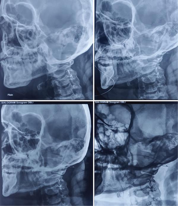
7. Irregular pooling of contrast and ductal obstruction without presence of calculus are indirect signs of malignancy (Fig. 3.1.6).
Fig. 3.1.6Sialogram demonstrating the Wharton’s duct. Positioning of cannula and scout image is also shown.
Dacryocystography
Dacryocystography (DCG) is a radiographic technique to visualize the nasolacrimal duct system following administration of contrast media.
Indication – To look for nasolacrimal duct stenosis/obstruction in patients with epiphora. Degree and level of obstruction or stenosis or the presence of fistulae, diverticula can also be evaluated by DCG.
Contrast media used – Oil-based or water-soluble contrast media can be used. Oil-based contrast media (Lipiodol) have the advantage of better opacification of the nasolacrimal duct than water-soluble contrast agents. But the disadvantage of oily contrast is that in case of extravasation, it can cause granulomatous reaction in the soft tissue. Aqueous solution in the form of methylglucamine diatrizoate 40% can also be used. It has the advantage of causing less irritation. Nonionic or lower osmolar aqueous solutions are preferred for use when combining DCG with digital subtraction techniques.
Lipiodol is the only contrast agent that is tasteless.
Technique
• Irrigation and expression of contents of the lacrimal sac has to be done before the procedure so as to remove thickened secretions. This is to avoid misdiagnosis of retained mucous as filling defects.
• Patient lies supine in the fluoroscopy table. Select small field of view and fine focus. Control images are taken.
• Anaesthetic eye drop is used for patient comfort.
• The inferior punctum is cannulated for the procedure. The cannula should remain stable during the whole procedure.
• 26-gauge lacrimal cannula with a plastic hub is used. Radiopaque contrast material is drawn into a small syringe and connected to the lacrimal cannula after removing air bubbles if any.
• Around 1–2 mL of contrast material is injected slowly. In bilateral imaging, a “Y” connector is routinely used in some centres.
• Frontal projection images similar to Water’s projection (40-degree occipitomental projection) are taken so that the nasolacrimal duct is parallel to the imaging.
• A coned-down occipitomental view, centered at the inferior orbital margin, can also be obtained.
• Images can be taken during injection for distension DCG, intubation DCG or digital subtraction DCG. A delayed image has to be taken, to look for any delay in drainage of contrast.
Digital subtraction DCG is a modification of this technique done under fluoroscopic control with further real-time imaging during the injection of contrast. Images are acquired every 1–2 seconds, and study can be terminated as soon as patency or obstruction is seen. Fewer images are acquired when compared with conventional DCG with less radiation dose.
Image interpretation
Drainage of tears is via the lacrimal canaliculi into the lacrimal sac and nasolacrimal duct, which further drains into the inferior meatus.
DCG identifies the level and extent (partial or complete obstruction) of occlusion and cause of obstruction such as calculus (seen as filling defects with abrupt luminal narrowing) or stricture (seen as irregular luminal narrowing). Mass lesions may be seen as displacing and distorting the duct system or as irregular filling defects with obstruction. DCG is also carried out in case of trauma to look for extravasation of contrast or NLD blockage. Fractures if any can be identified in scout imaging.
Complications – Contrast extravasation, injury to canaliculus, infection, granuloma formation.
Modifications of the technique
CT DCG, MR DCG (discussed later in this chapter).
Ultrasound technique in imaging of head and neck
• Ultrasound is the most commonly used imaging modality in head and neck lesions. It is noninvasive, easily available, with no radiation risk and can be performed real time with simultaneous assessment of the vascularity.
• USG has very good soft-tissue spatial resolution; hence, the details of relatively small neck nodes are better evaluated by USG than CT/MRI. Usually, USG is the only modality required to answer the clinical question.
• Another advantage of this modality is that guided FNAC/biopsy can be done in case of suspicious lesions. As the procedure is done under guidance, it carries less risk for the patient and the sampling can be specifically done from suspected areas.
• But it is operator dependent, and the structures beneath bones and air collections cannot be visualized.
Scanning technique
Ultrasound should be performed using a high-resolution linear probe (a 7.5- to 10-MHz probe).
A 5-MHz probe may be at times needed to visualize deeper structures.
A systematic scanning technique is needed to evaluate head and neck lesions.
Patient positioning – The patient lies supine with the neck hyperextended and a pillow or triangular soft pad under the patient’s shoulders and lower neck for support. The examination starts with a transverse scan of the submental region. The transducer has to be swept laterally to both sides of the neck. The patient’s head is turned towards the opposite side while scanning.
The submandibular region is further evaluated with a transverse scan along the inferior border of the mandibular body. The transducer is angled superiorly to examine submandibular nodes. The transducer is then swept along the ramus of the mandible to assess the parotid region with longitudinal and transverse scans. The scanning is continued with examination of the internal jugular chain nodes and neck vessels. The internal jugular chain nodes are examined in transverse scans along the internal jugular vein and common carotid artery from the inferior end of the parotid gland to the junction between the internal jugular vein and the subclavian vein.
From the lower cervical region, the transducer is then swept laterally to the supraclavicular fossa where the supraclavicular region is examined with transverse scans.
Further the posterior triangle is assessed with transverse scans from the mastoid tip to the acromion process. The same scanning approach is used on the opposite side of the neck.
Ultrasound applications
Evaluation of neck nodes.
Normal lymph nodes are oval shaped with a longitudinal to transverse dimension ratio of >2. Abnormal lymph nodes, especially the metastatic nodes, appear round in shape. The reactive lymph nodes, tubercular lymphadenopathy and lymphoma can have rounded appearance.
Metastatic lymph nodes appear typically hypoechoic to skeletal muscle. When fatty hilum is well maintained, the node is more likely to be benign. However, when the fatty hilum is not seen, it could either be a benign or malignant. Loss of fatty hilum, necrosis, granular parenchymal echoes and extracapsular spread are typical findings seen in metastatic lymph nodes. Intranodal punctate peripheral calcification is commonly seen in papillary thyroid carcinoma. Intranodal cystic necrosis is common in papillary carcinoma thyroid and squamous cell carcinoma. Matting is seen in tuberculous nodes. On Doppler study, hilar vascularity is seen in benign nodes, and peripheral mixed vascularity is seen in malignant nodes.
Examine the soft-tissue adjacent to the neck nodes. Adjacent infective/inflammatory changes may be there in tuberculous nodes and postradiation therapy. Malignancies of breast and lung can also have metastatic lymph nodes especially in the supraclavicular fossa and posterior triangle.
Division of the internal jugular chain nodes – Upper cervical nodes are above the level of the hyoid bone, middle cervical nodes are between the level of the hyoid bone and cricoid cartilage and lower cervical nodes are the ones below the level of cricoid cartilage.
Evaluation of neck lumps.
Ultrasound is the initial imaging modality for neck masses in adults and children for common lesions including haemangioma, lymphangioma, branchial cleft cysts, malignancies, infectious processes such as cellulitis and abscess, etc.
Gel mound may be used for superficial lesions, and it allows for visualization of the most superficial aspects of a lesion. Comparison of the scanned area with the opposite side helps in better characterization of the lesion.
Ultrasound can distinguish solid from cystic lesion, abscess from areas of cellulitis/soft-tissue oedema, highly vascular lesions from less vascular lesions and vascular malformations. Ultrasound is also very helpful for image-guided biopsies of nonpalpable or small lesions.
However, to evaluate deeper extension to skeletal structures, neurovascular bundle, intrathoracic and intracranial extension cross-sectional imaging has to be done.
Sometimes, an infected cystic mass may be mistaken for a solid lesion in ultrasound. Similarly, complete necrosis within a lymph node may also be mistaken for a cystic lesion. Hence, a detailed evaluation of the lesions with respect to its margins, vascularity, etc. is very important.
Ultrasound is also used for the initial evaluation of floor of the mouth lesions. High-frequency ultrasound evaluation of the floor of the mouth is done in the submental region. However, deep structures cannot be well evaluated. Intraoral ultrasonography is at times used for better visualization of deeper structures. Common lesions imaged include ranula, dermoid, lymphangioma, metastatic lymph nodes, etc.
Evaluation of thyroid gland.
The patient is in supine or semirecumbent position with neck in extension. Ultrasound is the basic investigation for thyroid enlargement. Both lobes of the thyroid gland are examined in longitudinal and transverse planes.
The normal thyroid tissue appears homogeneously echogenic with a uniform echotexture. Colour Doppler is used to evaluate the vascularity of the gland as well as nodules. Ultrasound examination gives the details regarding size, location, composition and echogenicity of the nodule with respect to adjacent structures. The margins of the lesion should be examined. Presence of rim calcification or halo and other features such as colloid calcification and vascular pattern should be given importance. Characteristics of adjacent lymph nodes should also be evaluated. FNAC may be done from the most suspicious nodule or lymph node.
Evaluation of salivary gland.
Parotid gland – The echogenicity of the parotid gland is determined by the amount of intraglandular fatty tissue. If the intraglandular fat is more, then the gland will appear more hyperechoic. The deep lobe of parotid gland cannot be visualized on ultrasound. A parotid duct of normal caliber is usually not visible during US examination.
There may be intraparotid lymph nodes in the parotid gland predominantly in the upper and lower poles. If there is a hyperechoic hilum, the intraparotid lymph node is considered benign. Normal central vessels will be seen in benign intraparotid lymph nodes.
Submandibular salivary glands also appear homogeneously hyperechoic. The gland will appear markedly or slightly hyperechoic to the adjacent muscles.
Focal lesions will appear hypoechoic. Appearance of diffuse involvement of the gland depends on the chronicity. In acute inflammatory process, the gland appears swollen and hypoechoic with increased vascularity. In chronic inflammation, gland appears small in size and diffusely heterogeneous.
Ultrasound of parathyroid.
Normal parathyroid gland is not visualized on USG. In suspected cases of parathyroid adenoma, abnormal well-defined hypoechoic lesions with increased vascularity have to be searched for in the expected location of parathyroid gland. Longitudinal and transverse imaging from the carotid arteries on either side to the midline bilaterally, extending from the bifurcation of carotid artery superiorly to the thoracic inlet inferiorly, has to be done to search for ectopic parathyroid adenoma. The soft-tissue beneath the clavicle and visualized part of superior mediastinum has to be imaged. This is done by angling the probe behind the sternum.
Evaluation of carotid vessels and internal jugular vein.
Doppler study is used to evaluate the flow pattern in carotid vessels. The grayscale evaluation demonstrates presence of plaque, type of plaque, extend of stenosis, etc.
Role of colour doppler in evaluation of neck lesions.
Doppler evaluation is used to demonstrate the vascularity of the hilum of cervical and intraparotid lymph nodes, vascularity of gland in sialadenitis and thyroiditis.
Doppler evaluation is also helpful in evaluating the vascularity of a solid lesion, to determine whether AV malformation is high flow or low flow, to differentiate cystic lesion from solid lesion with necrosis, etc.
Evaluation of orbital lesions.
Imaging is performed with the patient in sitting or supine position with a 10- or 12-MHz high-resolution linear small-parts probe. The routinely used method is the contact method where the probe is placed over the closed eye lid using a coupling gel. The refracting transparent media in the eye consist of cornea, aqueous humour, the lens and the vitreous body.
Common indications for ultrasound of orbit
• Difficult visualization with ophthalmoscope due to opacification of light-conducting media
• Intraocular focal mass lesion
• Retinal detachment
• Lesions in the vitreous
• Foreign body localization
• Ocular measurements (A scan)
• Doppler evaluation of orbital vascular disease and tumours
Only gold members can continue reading. Log In or Register to continue
Mar 25, 2024 | Posted by admin in CARDIOVASCULAR IMAGING | Comments Off on Radiological techniques, protocols and basics of interpretation in head of neck imaging