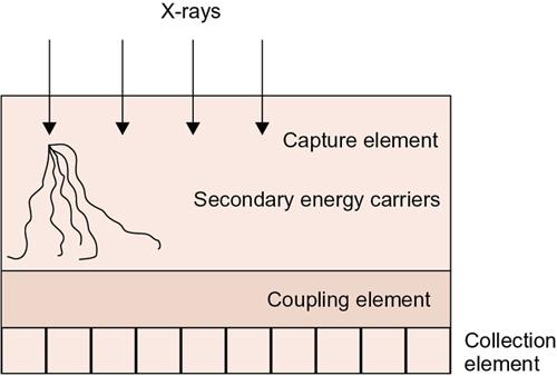
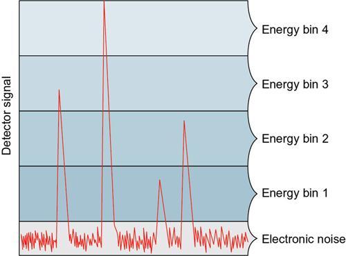
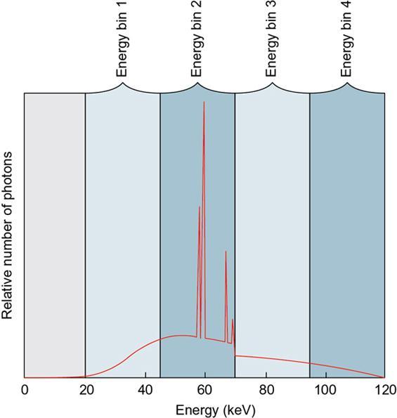
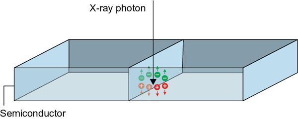
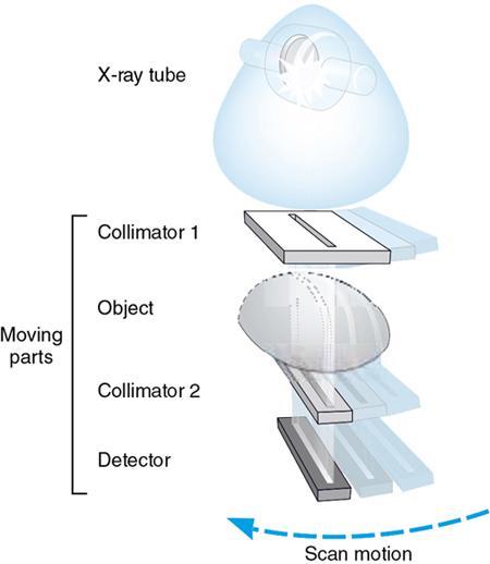
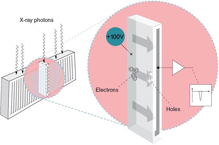
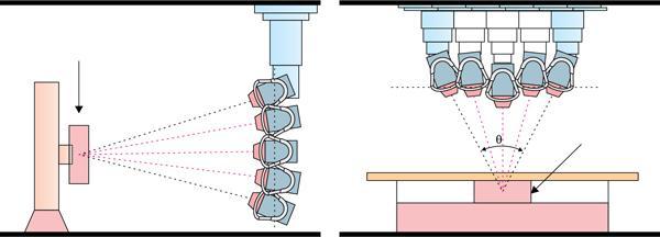
Alex Fernandus D, Binit Sureka, Pushpinder Singh Khera You never change things by fighting the existing reality. To change something, build a new model that makes the existing model obsolete. B. Fuller Digital radiography (DR) is a projection (2D) X-ray imaging technique that uses digital imaging technology in which the analogue signal acquired from the patient is transformed into a digital form, transferred to a computer and processed for digital display. Additionally, they can also be digitally stored, retrieved and communicated for fast distribution (e.g. picture archiving and communication system, hospital information system [HIS], radiology information system [RIS]). In contrast to conventional screen–film practices, DR uses digital detectors which can either be direct or indirect X-ray convertors. Direct detectors directly convert the X-ray signal into electric charges that can be further processed for transformation into a digital image, whereas in indirect detectors, the X-ray signal is first converted into visible light photons and then the light photons are converted into electric charges. In general, digital detectors consist of three distinct components: X-ray capture element, coupling element and collection element (see Fig. 1.25.1). Table 1.25.1 shows the common elements of DR detectors. Modified from Samei E, Peck DJ. Hendee’s physics of medical imaging. John Wiley & Sons; 2019 Apr 23. p. 234–236, 244, 261–262. CCD, charge-coupled device; CMOS, complementary metal-oxide semiconductor; TFT, thin-film transistor. Some of the advantages of digital detectors over conventional analogue systems include wide dynamic range, increased dose efficiency, reduced patient exposure, image postprocessing and electronic storage, retrieval and distribution. Other advancements include but not limited to photon-counting detectors (PCDs), tomosynthesis, dual-energy imaging, computer-aided detection and diagnosis, automatic image stitching, mobile DR, wireless flat-panel detectors (FPDs), mobile computed radiography (CR) and new structured phosphors in computer radiography, which are discussed in the following subsections. One of the advancements in the digital imaging systems include photon counting receptors which interact with incident photons one by one and detect each photon (a count), and the specific energy range within each photon can be identified (energy discriminated count). In comparison with the conventional energy-integrating detectors (EIDs) that work in a current mode (integrate deposited energies from all photons), PCDs are operated in a pulse mode based on single event in which each photon interaction with the detector can be processed and registered individually (count individual photons while measuring energy information). Each of the registered photon gives rise to an electrical pulse in the detector read-out electronics with respect to time, and the height of each pulse is proportional to the individual photon energy. The detector counts only the number of pulses with a height larger than a preset threshold, thereby eliminating electronic noises (that are present below the threshold). By setting more than one threshold, the registered photons can be sorted into several energy bins on the basis of their energy range (see Figs 1.25.2 and 1.25.3). The PCD systems have been developed with the capture elements such as gas, scintillator or semiconductor material mediums and coupled to a collection element through which the detected X-ray signal is either directly or indirectly measured in terms of electric charges and used for further process and analysis of the acquired signal. In a semiconductor-based PCD (direct detector) currently used in the field of X-ray imaging, a large voltage is applied on it, and when an incident X-ray is absorbed in the semiconductor, a cloud of positive and negative charges are generated and collected by the electrodes connected to an electronic read-out circuit (see Fig. 1.25.4). Semiconductors made up of silicon (Si, Z = 14) is typically used for lower X-ray energies due to its low absorption efficiency in lower energy ranges (e.g. Si-strip detectors are used in PCD-based mammography systems with scanning multislit geometry – see Figs 1.25.5 and 1.25.6). For higher X-ray energies, more X-ray absorbing capture elements have been developed and are clinically used due to their higher absorption efficiency, namely, cadmium telluride (CdTe, Z = 48/52) and cadmium zinc telluride (CZT, Z = 48/30/52). The thicknesses of the X-ray-absorbing crystals may be increased to attain greater absorption efficiency. Some of the benefits of PCDs over the conventional EIDs include reduced electronic noises, higher contrast-to-noise ratio, improved dose efficiency and simultaneous multienergy imaging. The scope of PCDs is currently studied and being developed and is hoped to be clinically available in the future (e.g. photon-counting multienergy CT). Tomosynthesis is an advanced cross-sectional digital imaging technique developed from conventional tomography that can remove overlying structures and reveal anatomical structures present at different depths or planes inside the patient. In digital tomosynthesis (DT), the X-ray tube is moved around the patient’s anatomical region of interest, with a limited number of projection angles (limited angular range), in a continuous or discrete (“step and shoot”) manner. The detector could be stationary or dynamic depending upon the system (see Figs 1.25.7 and 1.25.8).
1.25: Recent advances in radiography
Digital radiography
Detector Technology
Typical Capture Element
Typical Coupling Element
Collection Element
X-ray Conversion Type
Computed radiography
Photostimulable phosphor (e.g. BaFBr)
Laser-prompted photostimulable light guide
Photomultiplier tube; signal digitization
Indirect
CCD/CMOS-based
CsI or G2O2S phosphor
Lens or fibre-optic taper
CCD or CMOS
Indirect
Indirect flat panel
CsI or G2O2S phosphor
Contact layer
Photodiode/TFT array
Indirect
Direct flat panel
a-Se or CdZnTl
None
TFT array
Direct
Photon counting system
Tomosynthesis
Related posts:

Stay updated, free articles. Join our Telegram channel

Full access? Get Clinical Tree


