Fig. 5.1
Curved array transducers are used for the performance of renal ultrasound. Seen in this image are two different widths of curved array transducers, large footprint (left) and small footprint (right)
Most commonly, one or two focal zones are used for renal imaging. The focal zone should correspond to the area of interest in the field of view. The focal zone represents the narrowest part of the ultrasound beam and gives the best lateral resolution at the region of interest. Adding focal zones reduces the refresh rate of the image, which can slow down the performance of the ultrasound examination. Several additional ultrasound features are often helpful during a renal examination. These include Doppler mode with calculation of resistive index, cine loop (capture of live images), and measurement calipers.
Patient Preparation
Patient preparation is helpful to facilitate an efficient exam. Fasting decreases intestinal contents and can allow for a more anterior window for imaging the kidney. This can avoid the thicker flank musculature and take advantage of the liver as a window to the right kidney. In the urology office, however, renal imaging is often performed on short notice to investigate an acute problem during the appointment. Thus, it is usually impractical to have the patient fast several hours prior to the exam. For planned examinations, such as upper tract imaging for a hematuria workup or screening for postoperative hydronephrosis after endoscopic stone extraction, the patient should fast for 6 h prior to the examination.
The exam room should have the capability to dim room lights and reduce glare from natural lights. The ultrasound image detail on the screen is dramatically improved by reducing ambient light.
Patient positioning will depend upon the indications for the exam. A focused unilateral follow-up exam such as for a post-ESWL hematoma or for renal trauma can be done efficiently with the patient in supine position. However, larger patients with more truncal obesity are likely best imaged in the lateral position since this allows for both coronal and sagittal (lateral and posterior) imaging of the particular renal unit. A bilateral examination will likely then involve moving the patient from supine or right lateral to left lateral position to image the left kidney. Ultrasound for urolithiasis will involve imaging from the high posterior flank coursing inferiorly to the lower anterior abdominal wall. Ultimately evaluation of the ureterovesical junction (UVJ) will include attempts to locate a distal stone and document ureteral jets.
The ultrasound machine should be positioned so that the screen is easily visible to the operator and that the keyboard and patient can be reached comfortably. Extreme care should be taken to avoid falls caused by rolling patients from side to side on a standard examination table. Typical exam tables are narrow and have no side rails. The physician’s attention will likely be focused on the ultrasound monitor so that ancillary staff should observe unsteady patients.
Anatomic Considerations for Renal Imaging
Ultrasound evaluation of each renal unit is influenced by the orientation of the kidney in the retroperitoneum. Figures 5.2 and 5.3 demonstrate the anatomic position of the right and left renal unit. The lower pole of the right kidney is 15° lateral to the upper pole in the coronal plane. The renal hilum is rotated approximately 30° posterior to the horizontal coronal plane when examined transversely. The psoas muscle displaces each kidney such that the lower pole is more anterior than the upper pole. For longitudinal views, the orientation of the ultrasound probe should match the long axis of the kidney as depicted in Fig. 5.3. This will allow identification of the true midsagittal plane of the kidney.


Fig. 5.2
(a) Coronal MRI showing that the lower pole is 15° lateral to the vertical plane. (b) Transverse MRI at the level of the renal hila showing that the axis of the kidney is 30° posterior to the true coronal plane. (c) MRI demonstrating that the lower pole of the kidney is anterior to the upper pole
Fig. 5.3
Image of an MRI demonstrating the anatomical position of the kidney in the abdomen and proper position and angle of the ultrasound probe for imaging the left kidney. This probe position would generate a true midsagittal ultrasound image of the left kidney
Imaging the Right Kidney
Technique
Ultrasound imaging of the right renal unit can be performed in either the supine or flank position. In the flank position, the patient’s right arm should be positioned over their head with a possible pillow under the left flank to open the space between the ribs and the iliac crest. The transducer is placed in the midclavicular line at the level of the costal margin. Bowel gas in the transverse colon will often be encountered initially. The flank position can allow lateral imaging (through a coronal plane) or through a posterior window that can avoid the gas. The transducer is swept laterally using the liver as an acoustic window to image the upper portion of the kidney. Figure 5.4 is an example of a right kidney viewed through a liver window. The homogeneous composition of the liver offers excellent transmission of the sound waves with minimal distortion. The echogenicity of the liver also offers a comparison for the appearance of the renal parenchyma. The kidney is expected to be isoechoic or hypoechoic to the liver. The finding of renal parenchyma that is hyperechoic to the liver suggests the presence of renal disease.

Fig. 5.4
Right kidney viewed using the liver as an acoustic window
The transducer is moved over the kidney in both transverse and longitudinal (both coronal and sagittal) planes from any window provided by the position of the patient. It is helpful to locate the true sagittal section of the kidney. This serves as an anatomic landmark from which the remainder of the scan can be performed. The midsagittal plane of the kidney is characterized by the longest measurable sagittal axis of the kidney. It is important in a routine renal ultrasound examination to document the parenchymal length in this plane. A normal adult renal length is between 9 and 12 cm.
Once the midsagittal plane is located, the kidney should be scanned both anteriorly and posteriorly until the entire renal parenchyma has been evaluated. The upper pole and the midportion of the kidney can usually be viewed through the liver window. The lower pole frequently has to be imaged directly through a more lateral or posterior location. It is also often necessary to have the patient take and hold a deep breath while imaging the full aspect of the renal parenchyma. Figure 5.5 is an example of the lower pole of the left kidney viewed directly from the flank rather than through the spleen as an acoustic window. This is analogous to imaging the right kidney directly through the flank while the patient holds a deep breath.
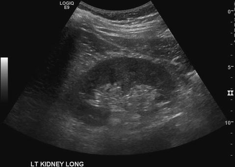
Fig. 5.5
Left kidney viewed directly via lateral flank approach (true midsagittal plane)
Once the longitudinal imaging has been completed, the transducer may be rotated to achieve a transverse view of the kidney. The mid-transverse plane can be identified by the characteristic horseshoe-shaped renal parenchyma, which is discontinuous on the medial aspect at the level of the renal sinus and vessels. It is often possible to visualize the renal artery and vein through this window. Although the renal artery is sometimes more difficult to identify than the vein, both vessels may be distinguished with the color flow Doppler analysis. It is in the transverse plane that measurements of parenchymal thickness, as well as cortical thickness, can be obtained and documented. The color Doppler function with spectral display can be used to calculate the resistive index. This measurement may be useful in characterizing renal vascular disease, renal parenchymal disease, and obstruction [5, 6].
Imaging the Left Kidney
Technique
Ultrasound of the left renal unit is typically performed with the patient in a lateral position with the left arm raised overhead to open the intercostal spaces for better imaging. The transducer is placed at the midaxillary or posterior axillary line. Bowel contents commonly prevent an anterior approach to viewing the left kidney. The left kidney image is often less crisp due to attenuation and scattering from muscle in the flank and back. The spleen is frequently seen anterior and superior to the left kidney but is not usually well positioned to use as an acoustic window. This is illustrated in Figs. 5.5 and 5.6. Similar to the right renal ultrasound examination, having the patient take and hold a deep breath often brings both the spleen and the upper aspects of the kidney into view.
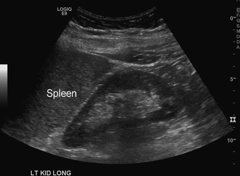
Fig. 5.6
The spleen is seen on this image cephalad to the left kidney
The true midsagittal plane of the left kidney is then located. This will be the plane of the longest sagittal parenchymal length. The renal capsule will appear discontinuous at the mid kidney medial at the site of the renal hilum. In the coronal view, cortical tissue is seen as a continuous ring around the hyperechoic pelvic sinus fat except at the renal hilum. Once the anterior and posterior surfaces of the kidney have been fully imaged in the sagittal plane, the transducer is rotated to obtain a transverse image. It is always important to remember standard radiologic convention establishing the medial aspect of the kidney on the left side of the ultrasound monitor. This means that the renal vessels should point towards the left side of the monitor during transverse imaging.
The upper and lower portions of the left kidney are imaged completely by moving the probe cephalad and caudad while asking the patient to hold a deep breath. A deep inspiration and expiration will move the kidney several centimeters. The mobility of the kidney can be assessed for possible evidence of a mass, inflammation, or anatomic abnormalities. Once the kidney has been completely evaluated in all planes, attention is then turned to identifying and documenting normal and abnormal findings in a manner similar to the right renal exam.
The goal of the ultrasound exam is to view the entire renal parenchyma and the entire capsular surface. When imaging in the transverse plane, the entire length of the kidney must be viewed. Through the use of directed patient breathing, a scan can be performed from the adrenal superior to the kidney down to below the lower pole. The cross-sectional diameter of the renal capsule becomes smaller as the lower pole is reached. This then disappears as the imaging beam extends beyond the lower pole. An edging artifact is often encountered at the final rounded edge of each renal pole. This artifact can be eradicated by moving the transducer slightly to complete the imaging of the extent of the renal parenchyma .
A good analogy is the way one would view the renal axial imaging on a CT scan. Images can scroll through the kidney from just cephalad to the upper pole to just below the kidney to avoid missing any exophytic lesions. When imaging in the longitudinal plane, the probe can be fanned both anteriorly and posteriorly (both coronal and sagittal planes) to completely evaluate the renal unit from the anterior surface to the posterior capsule. Figure 5.7 demonstrates an MRI, which depicts a posterior exophytic mass that could be missed with incomplete imaging of the full capsular surface of the kidney .

Fig. 5.7
This MRI demonstrates a small exophytic renal cyst (arrow) that could easily be missed on ultrasound if the full anterior and lateral surface of the left kidney is not evaluated
Normal Findings
The renal contours should be smooth and of an ovoid reniform shape. Any deviation from a smooth uniform contour should be noted and a representative image saved. All surfaces of the kidney should be scanned from the top to the bottom and from anterior to posterior.
The kidney measurements should be recorded in both transverse and longitudinal planes. The transverse view of the mid kidney should be measured and a representative image saved. These measurements can include parenchymal thickness , cortical thickness, and possibly renal width from lateral capsule to medial extent of renal sinus. An image of the midline longitudinal length should be measured, including anterior to posterior height as well as length, and saved. Care should be taken to ensure that an accurate midline longitudinal view of the kidney is obtained for measurement of the parenchymal length. It is quite easy to obtain an oblique image that appears to represent the full length of the kidney anatomically with a resultant shorter measured length. Figure 5.8 demonstrates that there may be a substantial difference in the measurement of the long axis of the kidney if the renal unit is measured in a parasagittal plane versus a true midsagittal plane. The true midsagittal plane is characterized by a medial discontinuity of the renal parenchyma representing the hiatus through which the renal vessels and collecting system enter and exit.

Fig. 5.8
An accurate measurement of renal length depends upon obtaining a truly midline renal image in the sagittal plane. In ultrasound image (a) the right kidney is in the true midline as noted by the medial discontinuity of the renal parenchyma . This represents the hiatus through which the renal vessels and collecting system enter and exit (arrow). The kidney on this view measures 9.53 cm. Ultrasound image (b) demonstrates the measurement of the same right kidney when it is not in the true midline. The kidney measures 7.71 cm
Normal adult kidneys measure 9–12 cm longitudinally, 5–7 cm in transverse width and 3 cm in anteroposterior dimension [7]. Han and coworkers also provided information regarding normal renal measurements in pediatric patients [8]. Although there is a normal variation in the anatomy of each renal unit in an individual patient, a difference in length of more than 1.5 cm is considered abnormal [9].
Renal cortical thickness should be uniform throughout the kidney. Any bulges or indentations in the cortex should be noted on the report and captured as an image. Parenchymal and cortical thickness should be noted. The cortical thickness is measured from renal capsule to the base of the triangular medullary pyramids. The parenchymal thickness is measured from the renal capsule to the edge of the renal sinus. In adults, the medullary pyramids are often indistinct on ultrasound imaging making the measurement of cortical thickness inaccurate. Therefore, parenchymal thickness is often easier to measure. A renal parenchymal thickness under 1 cm is considered abnormal [9]. Figure 5.9 demonstrates cortical versus parenchymal thickness measurements.

Fig. 5.9
Image demonstrating the difference between the measurement of the cortical thickness and parenchymal thickness
The echotexture of the kidney should be described. The normal adult renal cortex should appear hypoechoic or isoechoic relative to the normal liver or spleen. The normal cortex should appear homogeneous in echogenicity. The medullary pyramids should be hypoechoic to the renal cortex. This distinction is much more pronounced in children compared to adults.
The renal sinus is hyperechoic compared to the renal parenchyma in normal renal units. The renal sinus is highly echogenic due to its many different reflectors including blood vessels, sinus fat, and the collecting system.
Adjacent Structures
Renal ultrasound by urologists is usually performed for a specific clinical indication and is focused on the kidneys. Adjacent organs will be in the field of view and any remarkable findings of those organs should be noted.
The adrenal gland in adults is not normally visualized on ultrasound. However, specific attention to the tissue anterior and medial to the upper pole of each kidney can reveal the normal adrenal gland and represents a potentially useful tool for examining adrenal lesions [10]. A prominent adrenal gland seen on ultrasound should be considered potentially abnormal and further imaging with CT or MRI can be considered.
It is not the intention of a focused urologic examination to provide complete imaging of the liver, gallbladder, spleen, or aorta. However, any abnormalities noted in these organs during the renal exam should be documented and further testing pursued as appropriate. Often the urologist has an ongoing relationship with the patient and may be able to provide valuable information regarding ancillary findings to the patient.
Ultrasound Report
The importance of a detailed and accurate ultrasound report cannot be overstated. The generation of the ultrasound documentation is a critical component of all renal ultrasound examinations and is routinely audited by other entities for clinical information, appropriateness of the examination, and reimbursement. The report has four components: indications, equipment, findings, and impression.
Indications
The clinical history and reason for performing the study should be documented in the indication section.
Equipment
Each ultrasound report should identify the make and model of the machine that is used for the exam. Additionally, the type of probe, frequency, and any pertinent modifications of US power, Doppler and elastography (if applicable) should be mentioned.
Findings
The findings section should include a succinct description of the normal findings as well as any notable abnormalities. Specific aspects of the report can also be reviewed in the AIUM report on urologic ultrasound guidelines [4]. Formal ultrasound terminology should be used with the findings described without an associated diagnosis. The diagnosis should be reserved for the impression section of the report. For example, one should report, “a 9 mm brightly hyperechoic focus in the lower pole of the right kidney with strong posterior acoustic shadowing” in the findings and report “consistent with the appearance of a stone” in the impression.
Impression
The impression portion of the report should include an interpretation of the sonographic findings based on clinical history and associated physical findings. When the urologist is the ordering, performing, and interpreting physician, the impression may also include a plan for subsequent imaging or intervention.
Image Documentation
Representative images of the exam should be captured and saved in the permanent patient record. These can be digital or hard copy images. It may also be possible to capture the actual cine loop of an examination. This approach has been found to improve the subsequent review of the exam by other providers [11]. Minimum image documentation will vary based on the clinical indication for the study but for a full examination of both renal units captured images should include:
- 1.
Right Kidney
- (a)
Longitudinal view with length measurement
- (b)
Transverse view of the upper pole
- (c)
Transverse view of the lower pole
- (d)
Transverse view of the renal pelvis
- (e)
View showing the liver and right kidney on the same image, if possible
- (a)
- 2.
Left Kidney
- (a)
Longitudinal view including length measurement
- (b)
Transverse view of the upper pole
- (c)
Transverse view of the lower pole
- (d)
Transverse view of the renal pelvis
- (e)
View showing the spleen and the left kidney on the same image, if possible
- (a)
- 3.
Appropriate views of abnormalities, with measurements if indicated
Doppler
Color and power Doppler are useful tools in renal imaging. The ability to confirm normal blood flow in the kidney can be valuable in the follow-up of trauma, partial nephrectomy, and obstruction. The ability to characterize hypoechogenic structures in the kidney relative to blood flow can influence the diagnosis and future intervention. The application of Doppler mode can quickly distinguish between vessels and hydronephrosis (Fig. 5.10). The use of Doppler to demonstrate renal artery stenosis is generally beyond the scope of office urologic practice.

Fig. 5.10
The anechoic area (arrow) seen centrally in image (a) which has an appearance consistent with hydronephrosis is found to represent hilar vessels by color Doppler in image (b). In a different kidney, the central anechoic area (arrows) in the transverse image (c) remains anechoic (arrow) during application of Doppler indicating a dilated collecting system
Resistive Index
Resistive index is a calculated metric that represents the degree of downstream resistance to blood flow measured at a specific point in a blood vessel. In the kidney, it is calculated by quantifying the velocity of blood flow from the Doppler waveform of intrarenal arteries. The arcuate arteries running along the junction of the cortex and medulla or the interlobar arteries running between the medullary pyramids are targeted. Color or power Doppler can be used to identify a suitable vessel. The Doppler angle indicator is aligned with the long axis of the blood vessel being interrogated and the gate set at no greater than 75 % of the inner diameter of the vessel. The angle of insonation (Ø) should always be ≤60°. The resultant waveform is analyzed (Fig. 5.11). The peak diastolic and end systolic velocities are marked. The formula to calculate resistive index (RI) is peak systolic velocity (PSV) minus the end-diastolic velocity (EDV) divided by the PSV (PSV − EDV/PSV). A value of <0.7 is generally accepted as normal. Higher RIs can be seen normally in children and the elderly. Comparing side-to-side RIs, called resistive ratio, may be useful. A resistive ratio is the ratio between the RI of the affected kidney and the contralateral normal kidney. However, a difference in the RI of >0.1 on the symptomatic side compared to the asymptomatic side may be more important than a resistive ratio clinically [12–14]. Studies have shown acceptable sensitivity and specificity for RI in evaluating obstruction [5]. Ureteral obstruction causes elevated arterial resistance even preceding the development of significant hydronephrosis [15–17]. Nonobstructive causes of renal pelvis dilation tend to demonstrate normal RIs. For example, pregnant women have been demonstrated to have normal RIs despite the development of hydronephrosis of pregnancy [18–20]. These studies suggest that ultrasound calculation of RI can be useful in distinguishing physiologic hydronephrosis of pregnancy from renal colic in pregnant woman while avoiding ionizing radiation .

Fig. 5.11
The accurate calculation of the resistive index depends on (a) aligning the angle indicator (yellow line) with the long axis of the vessel being imaged and (b) ensuring that the gate (two parallel green lines) is set to about 3/4 of the vessel width. The goal is to achieve an angle of insonation (θ) of ≤60°. In this image, the angle is 50° (circle). The resistive index is calculated as 0.73
The RI seems to rise reliably only in complete obstruction. Studies which included patients with partial obstruction demonstrated a reduced ability to discriminate between anatomic obstruction from functional dilation [21, 22]. The resistive index is not reliable as an isolated finding to prove or disprove a clinically significant obstruction. Rather, it can be another useful finding of a point-of-service ultrasound examination to support or refute a diagnosis during a clinical patient encounter.
Related posts:

Stay updated, free articles. Join our Telegram channel

Full access? Get Clinical Tree


