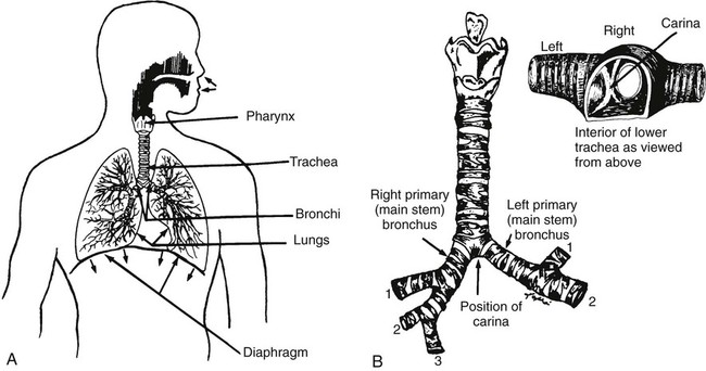
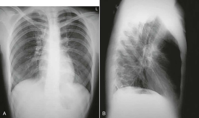
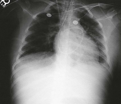
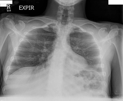
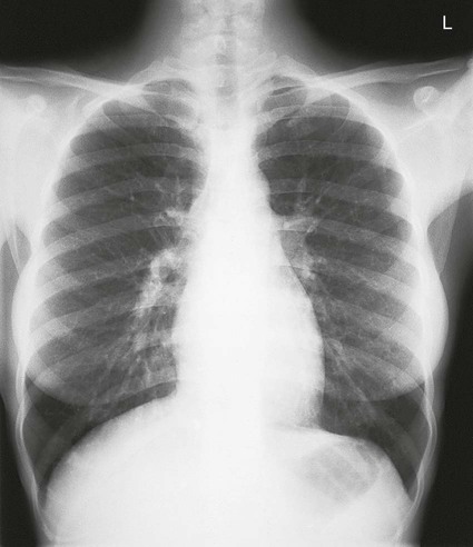
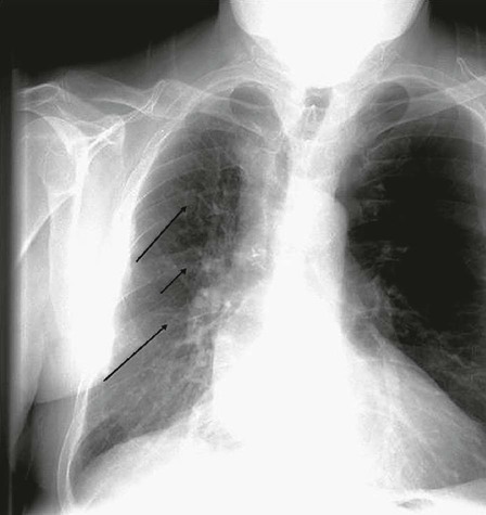
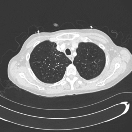
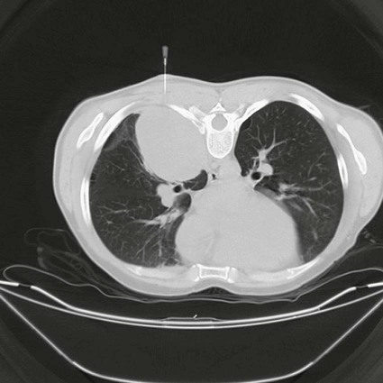
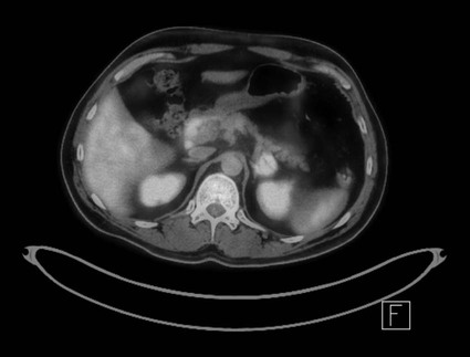
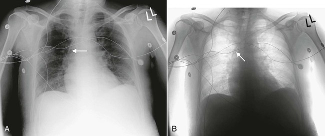
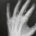
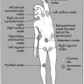
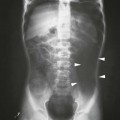
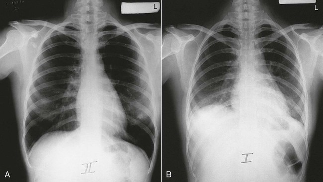
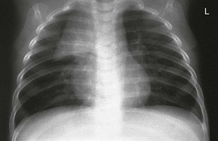
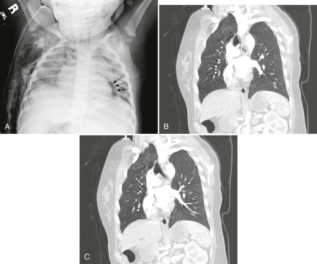
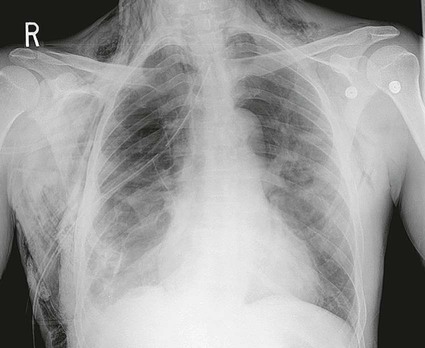
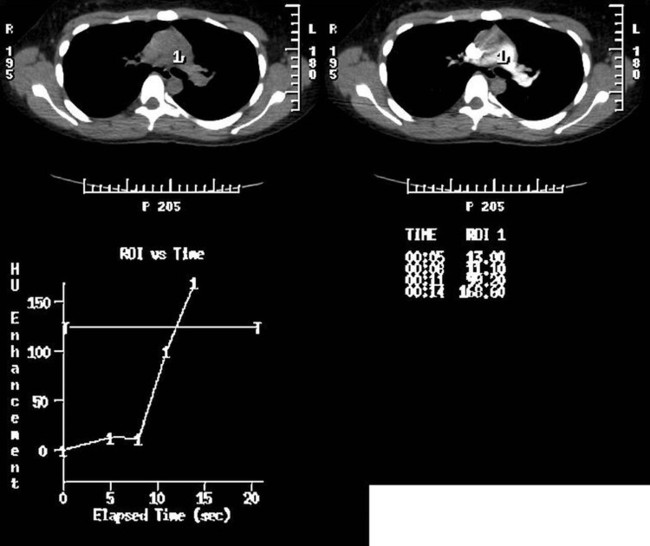
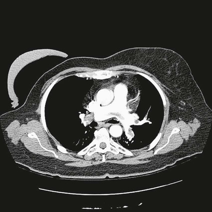
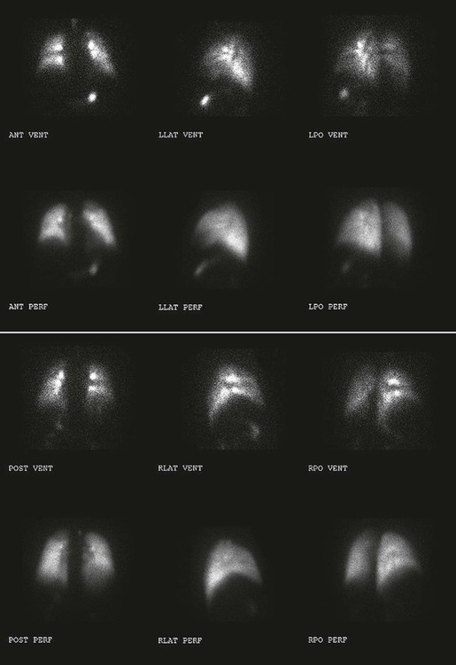
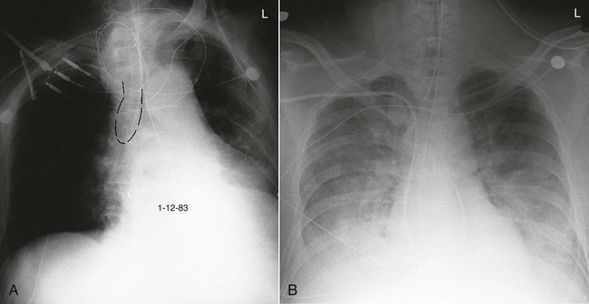
On completion of Chapter 3, the reader should be able to do the following: • Describe the anatomic components of the respiratory system. • Distinguish between the results obtained and uses for the various projections of the chest. • Describe the various types of tubes, vascular access lines, and catheters used in relation to the respiratory system. • Characterize a given condition as congenital, inflammatory, or neoplastic. • Identify the pathogenesis of the chest pathologies cited and the typical treatments for them. • Describe, in general, the radiographic appearance of each of the given pathologies. The respiratory system is responsible for two major functions. Ventilation involves the movement of air in and out of the lungs, and diffusion relates to the gas exchange between the lungs and the circulatory system. This system is usually subdivided into the upper respiratory tract—the nose, mouth, pharynx, and larynx—and the lower respiratory tract—the trachea, bronchi, alveoli, and lungs (Fig. 3-1). The thoracic cavity consists of the right and left pleural cavities and the mediastinum. The parietal pleura lines the thoracic cavity, and the visceral pleura adheres directly to lung tissue. Patient position and projection are also critical exposure conditions that may distort the final image. Position refers to the arrangement of the patient’s body (e.g., erect, supine, recumbent), and projection refers to the path of the x-ray beam (e.g., anteroposterior [AP], i.e., entering through the body’s anterior surface and exiting the posterior surface). The standard projections for chest radiography are the erect posteroanterior (PA) and left lateral (Fig. 3-2). Each of these serves to place the heart closer to the film because the heart lies in the anterior part of the chest and mostly to the left side. When combined with a standard 72-inch source-to-image distance (SID), magnification of the heart is minimized. On a normal erect PA chest image, the costophrenic and cardiophrenic angles are demonstrated, with the right hemidiaphragm appearing 1 to 2 cm higher than the left because of the position of the liver. When a patient is radiographed in the recumbent position, the lower lung fields may be obscured because of abdominal pressure raising the level of the diaphragm (Fig. 3-3). For evaluation of the standard PA chest radiograph, the size and radiolucency of both lungs should be compared. Criteria for adequate inspiration and penetration of chest radiographs vary from institution to institution; however, a rule of thumb is that adequate inspiration should provide visualization of 10 posterior ribs within the lung field. In addition, all thoracic vertebrae and intervertebral disk spaces should be faintly visible through the mediastinum on an adequately penetrated chest radiograph. The average movement of the lungs and diaphragm between inspiration and expiration is approximately 3 cm (Fig. 3-4). Oblique projections of the thorax are useful in separating superimposed structures such as the sternum, esophagus, and thoracic spine. A lordotic chest radiograph is useful in demonstrating the apical regions of the lung, which are normally obscured by bony structures on the standard PA projection (Fig. 3-5). Certain diseases such as tuberculosis (TB) have a predilection for the apices. Various soft tissue densities are present on chest radiographs. They may vary with patient age, sex, and pathologic conditions. The pectoral muscles are normally demonstrated overlying and extending beyond the lung fields. Radiographs of both men and women demonstrate breast shadows in the midchest region (Fig. 3-6). These shadows are normally homogeneous in appearance, and female breasts may obscure the costophrenic angles. Elevation of the breasts may be necessary to better demonstrate the bases of the lungs. Surgical removal of one or both breasts is also evident on chest radiographs; breast prostheses, which appear as well-defined, circular, radiopaque densities, are also evident. Nipple shadows may be visible at the level of the fourth or fifth anterior rib spaces and may occasionally mimic nodules or masses in the chest. These soft tissue structures may be differentiated with nipple markers or oblique projections of the chest. The ribs, sternum, and thoracic spine enclose the thoracic cavity. These structures assist the technologist in the assessment of the technical adequacy of chest radiographs. Congenital anomalies of the ribs may be demonstrated (Fig. 3-7), as well as calcified costal cartilages. This calcification generally occurs in patients in their late 20s and beyond. Rib fractures may be seen (Fig. 3-8), sometimes with an accompanying pneumothorax. A depressed sternum (pectus excavatum) may also be demonstrated, possibly displacing the heart (Fig. 3-9). The thoracic spine may be assessed for scoliosis, which may affect the chest cavity, and kyphosis or compression fractures of the vertebrae. The mediastinum contains all thoracic organs except the lungs. The heart occupies a large portion of the mediastinum, and the shape of the heart varies with age, degree of respiration, and patient position. Other organs contained within the mediastinum include the thyroid and thymus glands and nervous and lymphatic tissues (Fig. 3-10). In infants, the mediastinum appears wide because the thymus is normally large in a healthy infant. On frontal projections, it may extend beyond the heart borders and caudally to the diaphragm, and on a lateral projection, it may fill the anterior portion of the mediastinum, which is normally radiolucent later in life. This radiographic appearance is readily visible on both PA and lateral views and is referred to as the “sail sign” because of its characteristic appearance (Fig. 3-11). Diagnosis is difficult because the width of the upper mediastinum varies greatly with the phase of respiration. A crying child may present an opportune moment for the technologist to make an exposure, but the resultant Valsalva maneuver adds to the distortion of the thymus. The Valsalva maneuver increases both the intrathoracic pressure and the intraabdominal pressure by asking the patient to inhale deeply and hold the breath to force the diaphragm and chest muscles against a closed glottis. True mediastinal masses are rare in infants and generally represent congenital malformations or neoplasms. In the mediastinum of older adults, the aorta dilates, and the aortic knob becomes much more visible. Mediastinal emphysema (pneumomediastinum) occurs when there has been a disruption in the esophagus or airway and air is trapped in the mediastinum (Fig. 3-12). It may result from chest trauma, endoscopy, or violent vomiting. When unaccompanied by a pneumothorax, spontaneous mediastinal emphysema is usually self-limiting, subsiding in a few days without complication. Air in the mediastinum from rupture of the esophagus (usually from vomiting) or a major bronchus (usually from trauma) is more serious and requires prompt diagnosis and surgical intervention. An esophagogram may be performed with a water-soluble contrast agent to verify that a leak has not occurred. When the pneumomediastinum is extensive, air may pass from the mediastinum into the subcutaneous tissues of the chest or neck, resulting in subcutaneous emphysema (Fig. 3-13). Diagnosis of this may be made by feeling air bubbles in the skin of the chest or neck. Volumetric CT offers the advantage of imaging the entire chest with one breath hold, which allows better evaluation of the chest, especially the diaphragm area. Advances in CT software allowing high-resolution, thin-slice thicknesses ranging from 1 to 1.5 mm (Fig. 3-14) and faster scan times, in combination with dynamic scanning (Fig. 3-15), have greatly enhanced the role of CT in chest imaging. CT is the method of choice for evaluation of pulmonary adenopathy. Standard radiography is only about 50% sensitive to chest disease, typically displaying advanced pathologic conditions. The excellent specificity of CT, however, may be a problem because most people have granulomatous disease, which is often benign. A rule of thumb for evaluating the character of a visualized nodule relates to its size: Those less than 1 cm in size are usually benign, and those larger than 1 cm may be malignant. Also, the presence of calcium within a nodule is a reasonable indication of benignancy, particularly in the middle of the lesion or diffusely within the nodule, but eccentric calcification may indicate malignancy. CT is also sensitive in detecting emboli within the thoracic vessels (Fig. 3-16). In fact, the current standard of care when a pulmonary embolus is suspected is a computed tomographic angiogram (CTA) of the chest with contrast. Chest CT is also indicated in the clinical staging of small cell lung carcinomas and in the detection of metastatic disease of the chest. Percutaneous transthoracic needle aspiration is commonly performed under CT guidance. Needle aspirations are performed to obtain cytologic specimens from lesions within the lungs (Fig. 3-17), pleural space, and mediastinum. Following the biopsy, chest radiographs may be obtained to check for a possible pneumothorax or hemorrhage. Perfusion and ventilation scans, as performed in nuclear medicine, are useful in evaluating chest disease, particularly in the case of obstructive disease and in cases of suspected pulmonary emboli when a CTA is contraindicated. Injection of a radionuclide into the venous system for a perfusion causes it to become trapped in the pulmonary circulation, allowing for γ-camera visualization of its distribution. In a ventilation scan, the patient inhales a radioactive gas (such as xenon) and holds the breath while an image is taken of the gas distribution throughout the lungs (Fig. 3-18). Positron emission tomography (PET) captures information regarding metabolic activity. The primary imaging agent used in PET of the lungs is fluorodeoxyglucose (FDG), making it useful in distinguishing benign and malignant lesions within the chest because it has the capability of imaging an increase in glucose uptake from neoplastic cells. FDG whole body PET is useful in the evaluation of solitary pulmonary nodules and in the staging of bronchogenic carcinoma (Fig. 3-19). An endotracheal (ET) tube is a large plastic tube inserted through the patient’s nose or mouth into the trachea. It helps to manage the patient’s airway, allows frequent suctioning, and allows mechanical ventilation. Its proper position is below the vocal cords and above the carina (Fig. 3-20). Movement of a patient with an ET tube should be done with great caution because inadvertent displacement or extubation may leave the patient without a patent airway. A chest tube is a large plastic tube inserted through the chest wall between the ribs. It allows drainage of air (e.g., pneumothorax) or fluid (e.g., pleural effusion or hemothorax) from the thoracic cavity (Fig. 3-21) and allows the lungs to inflate to help the patient breathe normally. Those placed lower on the chest wall are usually for fluid drainage; those placed higher are usually for air removal. After open heart surgery, a chest tube may be placed in the mediastinum for proper fluid drainage. Its location is midline, just below the sternum. The collection device attached to the chest tube must be kept below the level of the chest to allow for proper drainage. The amount of time a chest tube remains in the thorax is dependent on the amount of deflation of the lung. Central venous pressure (CVP) lines are usually inserted via the subclavian vein, but they may also be placed through the jugular vein, antecubital vein, or femoral vein. Proper insertion places the tip of the CVP catheter in the distal superior vena cava (SVC) just above the right atrium (Fig. 3-22). This catheter provides an alternative injection site to compensate for loss of peripheral infusion sites or to allow for infusion of massive volumes of fluids. In addition, it allows for measurement of CVP, which indicates the patient’s fluid status and provides information about the function of the heart’s right side. However, pulmonary artery catheters have largely supplanted the use of CVP lines for these purposes because they provide even greater accuracy in measurements. Chest radiographs are generally requested following the insertion of a CVP line to check for proper placement and the presence of a pneumothorax or hemothorax. Improperly placed catheters may result in cardiac arrhythmias.
Respiratory System
Anatomy and Physiology
Imaging Considerations
Radiography
Position and Projection
Chest Radiography
Soft Tissues of the Chest
Bony Structures of the Chest
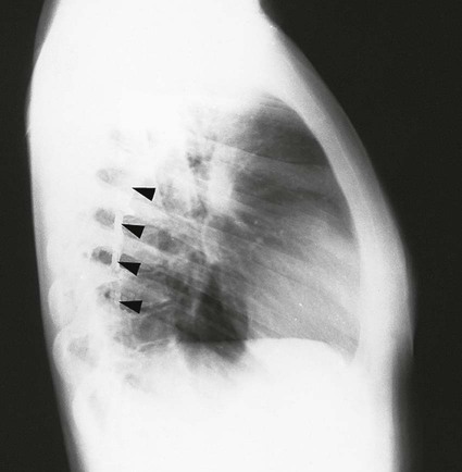
Mediastinum
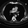
Computed Tomography
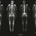
Nuclear Medicine Procedures
Chest Tubes, Vascular Access Lines, and Catheters
![]()
Stay updated, free articles. Join our Telegram channel

Full access? Get Clinical Tree


Radiology Key
Fastest Radiology Insight Engine