Screening Mammography
QUALITY-CONTROL TESTS
Quality-control tests done daily, weekly, monthly, quarterly, and semiannually by the technologists, as required under the Mammography Quality Standards Act (MQSA) (1) and the American College of Radiology (ACR) Mammography Quality Control Manual (2), are listed in Table 2.1. The reader is advised to consult this manual for details on how each test is done and interpreted. Any failures in daily processor quality control, weekly phantom images, semiannual darkroom fog, screen-film contact, and compression require corrective action before clinical imaging can be done (1,2). Failures in repeat analysis and fixer retention require corrective actions within 30 days of the test date.
Corrective action must be taken before any clinical imaging is done if daily processor quality control, weekly phantom images, and the semiannual darkroom fog or compression tests fail.
Quality-control tests that should be done at least once annually by a physicist are listed in Box 2.1. Corrective action needs to be taken within 30 days of the test date for failures in collimation assessment, system resolution, kilovolt (peak) [kV(p)] accuracy and reproducibility, automatic exposure control, system performance assessment, and uniformity of screen speed. Average glandular dose to an average (4.2-cm compressed) breast must not exceed 3 mGy (0.3 rad) per view for screen-film image receptors. The condition of the focal spot is evaluated by determining the system resolution and should be 13 line pairs per millimeter with the bars parallel to the anode-cathode axis and 11 line pairs per millimeter with the bars perpendicular to the anode-cathode axis. The kV(p) should be ±5% of indicated kV(p) (1,2).
Table 2.1: Quality-Control Tests (Technologist) | |||||||||||||||||||||
|---|---|---|---|---|---|---|---|---|---|---|---|---|---|---|---|---|---|---|---|---|---|
|
Box 2.1: Quality-Control Tests (Physicist)
Mammography unit assembly
Collimation assessment
Evaluation of system resolution
kV(p) accuracy and reproducibility
Beam quality assessment (half-value layer measurement)
Assessment of automatic exposure control system performance
Uniformity of screen speed
Breast entrance exposure dose, average glandular dose, AEC reproducibility
Image quality evaluation
Artifact evaluation
Viewbox luminance and room illuminance
kV(p), Kilovolt (peak); AEC, Automatic Exposure Control.
PHANTOM IMAGES
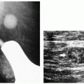
A basic understanding of phantom images is important because these serve to check that the x-ray imaging system and film processors are operating optimally with respect to film density, contrast (density differences), uniformity, and overall image quality. As part of the quality assessment and quality-control program, phantom images are done weekly. Phantom images are also done after equipment is serviced, when film or screen type is changed, or as needed when troubleshooting problems with the imaging chain. Although beyond the scope of this book, the reader is encouraged to review and understand how phantom images are obtained, evaluated, and scored (2). The phantom (Radiation Measurement, Inc. RMI 156 or Nuclear Associates 18-220) simulates a 4.2-cm thick compressed breast composed of 50% glandular tissue and 50% fatty tissue. It contains six fibers (range, 1.56 to 0.4 mm), five specks (range, 1.56 to 0.4 mm in diameter) and five masses (range, 2.00 to 0.25 mm in diameter). An acrylic disk (4-mm thick, 1 cm in diameter) is placed, or permanently attached to the phantom.
At a minimum, the four largest fibers, three largest speck groups, and three largest masses should be seen on images of the phantom.
At a minimum, the four largest fibers, three largest speck groups, and three largest masses should be seen. The image is also reviewed for artifacts, and these are factored into the scoring (Figure 2.1). Operating levels for background optical density should be at least 1.40 ± 0.20; background film optical density should never be less than 1.2, and the density difference due to the 4.0-mm acrylic disk should be at least 0.40 ± 0.05.
Operating levels for background optical density should be at least 1.40 ± 0.20 and should never be less than 1.2.
FILM LABELING
Mammography films are legal documents and must be labeled appropriately as required under MQSA (1). A permanent identification label must include the items listed in Box 2.2.
It is strongly recommended that a flash card with patient and location information be used. This is permanent and reproduces on copy films. The information should fit squarely in the designated space, be legible and not cut off. It is also recommended that technical factors used in obtaining the exposure be available as part of the permanent record. Fortunately, most new units flash some of the technical information onto the identification label. Troubleshooting suboptimal films, reproducibility, and comparison of technique from one year to the next are facilitated when the technical factors listed in Box 2.3 are known.
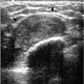
 Figure 2.1 Phantom image. Radiation Measurement, Inc. (RMI 156) phantom image demonstrating fibers (thin white arrows), specks (thick white arrow), and masses (M). Acrylic disc (D) attached to phantom is used in calculating density difference. Artifacts (black arrows) are noted and factored into the scoring of the phantom images. As part of the quality assessment and quality control program, phantom images are done weekly; the images should be retained for the past full year. |
Box 2.2: Required Information on Films
Patient name
Unique patient identifying number
Date of study
Radiopaque laterality and projection markers placed closest to axilla
Facility name
Facility location (minimum: city, state, and zip code)
Technologist identification
Cassette/screen identification number
Mammography unit identification number (if more than one unit/facility)
Box 2.3: Technical Factors Helpful in Troubleshooting Films
Target-filter combination
Milliampere-second (mAs)
Kilovolt (peak): kV(p)
Exposure time
Compression force
Compressed breast thickness
Photo cell positioning
Degree of obliquity on MLOs
MLO, mediolateral oblique views.
IMAGING ALGORITHM
By definition, screening mammography is done in asymptomatic women. We recommend annual screening mammography starting at 40 years of age. In women with a strong family history of breast cancer, we start screening annually at 30 years of age. Craniocaudal (CC) and mediolateral oblique (MLO) views of each breast are obtained for screening (3). At the discretion of the technologist, anterior compression and exaggerated craniocaudal (XCCL) views are obtained in a small number of women. A metallic BB is used to mark any prominent skin lesions that may be mistaken for a breast lesion. We require that the technologist document on the patient’s history form, the location and reason for using skin markers. Likewise, the presence of surgical scars is documented on a diagram of the breast provided for the technologist on the history form. We do not routinely use radiopaque markers on biopsy scars or the nipples.
As part of the screening study, anterior compression and exaggerated craniocaudal views are obtained in a small number of women to compress anterior tissue and image lateral tissue, respectively.
In women with implants, we obtain four views of each breast: CC and MLO views with the implants in the field of view and CC and MLO views with displacement of the implants (1,2,4). If there is significant encapsulation, implant-displaced views may not be obtainable. If these views cannot be done, it is documented in the mammography report and by the technologist in the patient’s history form. We do not obtain written consent for a mammogram from women who have implants.
IMAGING THE SMALL FEMALE BREAST OR MALE BREAST
In women with small breasts, or in male patients, it can be hard for the technologist to maintain the breast in place as compression is applied without scraping the skin over the knuckles. Compression paddles that are half the width of the standard compression paddle are available to overcome these limitations. These paddles are also helpful for achieving the implant-displaced views in women with implants.
IMAGING THE LARGE FEMALE BREAST
Image receptors, compression paddles, and cassettes come in two different sizes (18 × 24 cm and 24 × 30 cm). Selection should be based on the woman’s breast size. The large image receptor should not be used for women with small breasts. Likewise, a small image receptor should not be used on a woman with large breasts (Figure 2.2). In women with large breasts, a 24 × 30 cm image receptor is used, and more than two views of each breast may be needed to image all breast tissue adequately.
MEDIOLATERAL OBLIQUE VIEWS
Factors to consider in obtaining optimal tissue positioning on MLO views are listed in Box 2.4.
The angle of obliquity for MLO varies for different patients and is determined by the orientation of the pectoral muscle fibers. Tall women have a more vertically oriented pectoral muscle than short women. Our goal is to image as much breast tissue as possible and, because the breasts are skin appendages, pulling parallel to underlying relaxed muscle fibers maximizes the amount of tissue that is pulled away from the body (4).
Maximal tissue inclusion on mediolateral oblique views requires selection of a patientspecific angle of obliquity, relaxation of the pectoral muscle, and medial mobilization of the breast and underlying pectoral muscle.
Relaxation of the pectoral muscle requires that the patient inwardly rotate her humeral head and hold her arm down (behind or on the bucky). The patient should not lift her arm to hold onto the unit. The pectoralis major muscle inserts on the upper third of the humerus such that the muscle tenses when the arm is elevated and the humeral
head is externally rotated. Relaxing the pectoral muscle reduces the amount of resistance encountered during positioning so that a greater amount of tissue and muscle is routinely included on the images.
head is externally rotated. Relaxing the pectoral muscle reduces the amount of resistance encountered during positioning so that a greater amount of tissue and muscle is routinely included on the images.
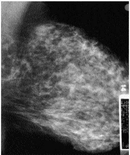 Figure 2.2 Inappropriate image receptor. Image receptor size needs to be matched to breast size. The anterior portion of this patient’s breast has been cut off from the image, and the cassette number and identification label partially obscure anterior tissue. This patient should have been imaged on a 24 × 30 cm cassette. |
Breast tissue in the lateral and inferior quadrants of the breast is mobile (Figure 2.3A). Tissue in the upper, and particularly the inner quadrants, has little inherent mobility. Unfortunately, most of our equipment is designed so that, for MLO views, the compression paddle travels from the upper inner quadrant to the lower outer quadrant (Figure 2.3B). As the compression paddle is put in motion, it attempts to mobilize tissue in the
upper inner quadrants with little inherent mobility. This results in the exclusion of variable amounts of tissue and potential lesions from the field of view and is associated with skin stretching that can be quite uncomfortable. The tissue rolls out as compression is applied. If we use natural breast mobility effectively, we can minimize the amount of excluded tissue and associated skin stretching (4). Therein lies the importance of medial mobilization of breast tissue and underlying muscle during positioning for MLO views. Every 1 mm of medial tissue mobilization represents 1 mm less of compression paddle traveling over fixed tissue.
upper inner quadrants with little inherent mobility. This results in the exclusion of variable amounts of tissue and potential lesions from the field of view and is associated with skin stretching that can be quite uncomfortable. The tissue rolls out as compression is applied. If we use natural breast mobility effectively, we can minimize the amount of excluded tissue and associated skin stretching (4). Therein lies the importance of medial mobilization of breast tissue and underlying muscle during positioning for MLO views. Every 1 mm of medial tissue mobilization represents 1 mm less of compression paddle traveling over fixed tissue.
Box 2.4: Factors to Consider in Positioning for Mediolateral Oblique Views
Technologist works from behind and medial side of patient
Angle of obliquity
Specific for every patient
Determined by technologist
Based on obliquity of pectoral muscle
Relaxation of pectoral muscle
Inward rotation of humeral head
Ipsilateral arm down
Medial mobilization of breast tissue and pectoral muscle
Need to maintain medial mobilization
Minimizes skin stretching upper inner quadrant
Patient needs to stay in unit
Breast out and up
Open inframammary fold
Include a small amount of abdomen
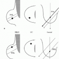
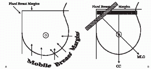 Figure 2.3 Breast mobility. A. The lateral and inferior portions of the breast are mobile. Upper and medial tissue is fixed in position. During positioning, tissue should be mobilized to minimize the amount of fixed tissue passed over by the compression paddle. B. For the mediolateral oblique (MLO) view, the compression paddle moves from the upper inner quadrant toward the lower outer quadrant. With little inherent mobility, upper inner quadrant tissue is excluded from the field of view as the compression paddle is mobilized for the MLO views. Associated skin stretching results from the paddle scraping over this tissue. For the craniocaudal view (CC), the compression paddle moves from the upper quadrants toward the lower quadrants. As the paddle moves downward, superior tissue can roll out from the under the paddle, and skin stretching leads to patient discomfort. |
The tip of the film holder is positioned at the apex of the axilla so that the film holder is snug against the body along the mid-axillary line. There should be no air gap between the pectoral muscle and upper portion of the breast and the film holder; otherwise, the pectoral muscle appears overexposed (Figure 2.4). Also, there should be no space between the film holder and the breast posteriorly; otherwise, posterior tissue is excluded. The technologist should not be able to advance her index finger into the apex of the axilla.
In assessing the adequacy of positioning on MLO views, consider the factors listed in Box 2.5. The length and shape of the pectoral muscle is evaluated in assessing the quality of positioning on MLO views (5). Pectoral muscle should be wide at the axilla, have an anterior convex margin, and extend to the level of the nipple (Figure 2.5). Lack of muscle relaxation, selection of an inappropriate angle of obliquity, failure to medially mobilize or maintain medial mobilization of breast tissue, or allowing the patient to lean back slightly can result in a concave pectoral muscle edge, a triangular pectoral muscle, or a muscle that is parallel to the edge of the film (Figure 2.6). The inframammary fold (IMF) should be open, and a small amount of abdomen is included on the image. The technologist should exercise care not to include too much abdomen or to allow a skin fold to develop up against the bucky laterally because this may limit compression (Figure 2.7). A small triangular density, superimposed on the pectoralis major muscle in a small number of women, is the pectoralis minor muscle (Figure 2.8).
The appearance of the pectoral muscle is helpful in assessing adequacy of positioning on MLO views. The muscle should widen at the axilla, extend to the level of the nipple, and have a convex anterior margin.
 Figure 2.4 Uneven exposure, air gap. The upper portion of the breast and pectoral muscle need to be directly on the film holder. This area of uneven exposure (arrows) is an indication that the tissue was not directly up against the film holder. An air gap is present. When areas like this are seen, evaluate the tissue carefully for blur because compression is not optimal in this area. Artificial calcification is incidentally noted. |
Box 2.5: Assessing Positioning on Mediolateral Oblique Views
Wide muscle (thick) at the axilla
Pectoral muscle to level of nipple
Convex anterior margin of pectoral muscle
Open inframammary fold
Small amount of upper abdomen
Breast pulled out and up (no sagging)
 Figure 2.5 Mediolateral oblique view. The pectoral muscles are thick in the axillary region, the anterior borders are convex and extend to the level of the nipple. The tissue is pulled up and out and is well compressed. With a bright light, the inframammary fold is noted and is open. |
 Figure 2.6 The pectoral muscle and mediolateral oblique views. A. Evaluation of the pectoral muscle is helpful in assessing positioning on mediolateral oblique views. Ideally, the pectoral muscle is thick at the axilla, has a convex anterior border, and extends to the level of the nipple. To accomplish this, the patient needs to be cooperative, and the technologist needs to match the angle of obliquity to the patient’s body habitus. Additionally, the pectoral muscle needs to be relaxed, mobilized medially, and maintained medially as compression is applied. When these principles are not followed, the muscle may be triangular in shape (B), be parallel to the edge of the film (C), or have a concave anterior margin (D). |
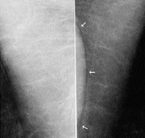 Figure 2.7 Skin fold. This skin fold develops laterally as the breast is being mobilized medially. Because the skin fold develops up against the film holder, the technologist does not see it during positioning. The lucency is air outlining the edge of the skin fold (arrows). Tissue surrounding skin folds needs to be evaluated carefully for blur. If the skin fold is adequately penetrated and there is no associated blur, it is not absolutely necessary to repeat this image. |
In some women, positioning may be limited secondary to a physical disability such as kyphosis, paraplegia, frozen shoulder, Parkinson’s disease, or absence of the pectoral muscle (Poland’s syndrome) (6) (Figure 2.9). We work closely with these women to obtain the best images possible. We document on the patient’s history form the patient’s limitations and our efforts to obtain adequate images.
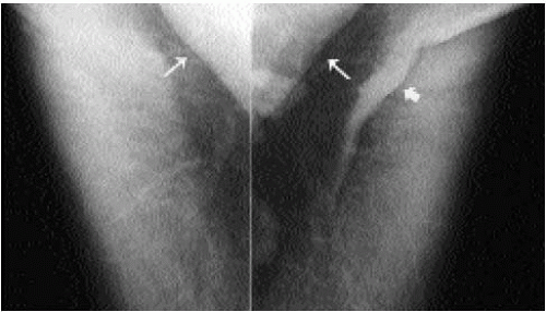 Figure 2.8 Pectoralis minor muscle. A triangular density seen superimposed on the pectoral major muscle is the pectoralis minor muscle (thin arrows). In this patient, the pectoralis minor muscle is seen bilaterally. A skin fold is noted on the left (thick arrow). Also note the air gap with uneven exposure particularly prominent on the left. |
 Figure 2.9 Poland’s syndrome. Absence of the pectoral muscle on the left. A. Craniocaudal views. The left breast is smaller than the right. B. Mediolateral oblique views. No pectoral muscle is imaged on the left. As in this patient, the breast on the affected side is usually smaller than the contralateral breast. Other ipsilateral chest wall abnormalities may be seen in patients with Poland’s syndrome. |
CRANIOCAUDAL VIEWS
In assessing adequacy of positioning on craniocaudal views, pectoral muscle should be seen in 30% to 40% of patients (4) (Figure 2.10A). If pectoral muscle is not seen, look for cleavage (Figure 2.10B). If pectoral muscle or cleavage is seen, you are assured that medial tissue has not be excluded from the image; if neither is seen, consider measuring the posterior nipple line (PNL; discussed later). Laterally, retroglandular fat should be seen; if tissue is seen to the edge of the film, an exaggerated craniocaudal view may be indicated.
Factors to consider in obtaining optimal tissue positioning on CC views are listed in Box 2.6.
In positioning for the CC view, the technologist should work from the medial side of the breast being imaged. As with MLO views, natural breast mobility is used to maximize the amount of tissue included on the images and to minimize skin stretching and tissue exclusion superiorly. The breast is taken at the neutral IMF position, lifted to the natural extent of mobility of the IMF, and pulled out away from the body (4). The bucky should not be placed higher than the elevated IMF position; otherwise, posterior tissue is excluded. As the breast is lifted, the technologist needs to be careful that a skin fold does not develop between the inferior aspect of the breast and the IMF. When present, this skin fold can simulate the pectoral muscle. A sharp lucency (air) outlines the edge of the skin fold but is not seen associated with the pectoral muscle (Figure 2.11). The position of the contralateral breast also needs to be considered. If the contralateral breast is left pendulous, it can be an impediment to the bucky going back against the chest wall. By placing the contralateral breast on the edge of the film holder, the bucky can be properly positioned against the chest wall. The technologist should ascertain that there is no space (air gap) between the chest wall and bucky (film holder); the technologist should not be able to place an index finger through the cleavage area.
Maximal tissue inclusion on craniocaudal views requires upward and outward pull of breast tissue as well as active tugging of lateral tissue without giving up any medial tissue.
The inclusion of medial tissue on CC views needs to be emphasized; however, as much as 2 cm of lateral tissue can be pulled into the image without giving up medial tissue
(Figure 2.12). The lateral aspect of the breast is mobile and has to be pulled actively into the image by the technologist as compression is applied. A skin fold may develop laterally as the technologist pulls lateral tissue in. This skin fold can be rolled out from underneath the paddle without losing tissue.
(Figure 2.12). The lateral aspect of the breast is mobile and has to be pulled actively into the image by the technologist as compression is applied. A skin fold may develop laterally as the technologist pulls lateral tissue in. This skin fold can be rolled out from underneath the paddle without losing tissue.
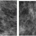
 Figure 2.10 Craniocaudal views. A. Pectoral muscle is seen in 30% to 40% of craniocaudal views. When pectoral muscle is seen, we are ensured that posterior tissue has been maximally included in the image. Retroglandular fat should be seen laterally (arrows). B. If pectoral muscle is not seen, look for cleavage (arrows). When cleavage is seen on craniocaudal views, we are ensured that medial tissue has not been excluded. It also indicates that the contralateral breast has been positioned appropriately so that the film holder can go back to the chest wall. If neither pectoral muscle nor cleavage is seen, measure the posterior nipple line to ensure that no significant amounts of tissue have been excluded from the craniocaudal view. |
In some women, the pectoral muscle is atrophied, and only the sternal insertion is seen medially on the CC view. The rounded or triangular appearance of the muscle in these women can simulate a mass (Figure 2.13). Alternatively, a round density seen on the CC view medially can represent the sternalis muscle. In some patients, the sternalis muscle can be seen in conjunction with the pectoral muscle (Figure 2.14). The sternalis muscle is an uncommon normal variant in chest wall musculature; it is a remnant of a muscle that would extend from the infraclavicular region to the caudal aspect of the sternum. It is commonly a unilateral finding. When the MLO is reviewed in these patients, no abnormality is seen.
Measuring the posterior nipple line is helpful in evaluating positioning on craniocaudal views in which no pectoral muscle or cleavage is seen.
Box 2.6: Factors to Consider in Positioning for Craniocaudal Views
Technologist works from medial side of patient
Identify neutral inframammary fold position
Lift breast up to extent of natural mobility of inframammary fold
Pull breast tissue out
Lateral tug: active pull of lateral tissue into field of view
Contralateral breast up on bucky (not left pendulous)
Bucky back to chest wall
 Figure 2.11 Skin fold. A. As the breast is mobilized upward, a skin fold can develop inferiorly. This skin fold can simulate the pectoral muscle. If evaluated carefully, however, a lucency (air) outlines the skin fold (thin arrows); this is not seen with the pectoral muscle (thick arrow). Because the skin fold develops up against the film holder, the technologist does not see it during positioning. B. Bilateral skin fold inferiorly (arrows). On the right, the skin fold simulates the pectoral muscle; however, because air outlines the edge, a lucency is seen (not seen with pectoral muscle). Skin fold on the left is smaller. |
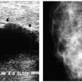
 Figure 2.12 Lateral tug for craniocaudal views. Invasive ductal carcinomas. Craniocaudal (CC) (A) and mediolateral oblique (MLO) (B) views. Tissue is seen extending to the edge of the film laterally on the CC view (arrows). A density is seen on the MLO view (arrow). C. CC view with lateral tug. Having the technologist actively tug on the lateral aspect of the breast brings the mass (thin arrow) into the image, and no medial tissue is given up. A skin fold (thick arrows) often develops laterally as the technologist tugs the lateral tissue into the field of view. D. Different patient. MLO views demonstrate a mass in the right breast (arrow). E. CC views. Mass is partially seen (thin arrow) laterally on the right. Pectoral muscle is seen (thick arrows). F. Repeat CC view with lateral tug. Mass (thin arrow) and additional posterior tissue, including a lymph node (thick arrow), are now included on the image. During positioning for CC views, the technologist should actively tug on the lateral aspect of the breast. This will routinely increase the amount of lateral tissue that is imaged. |
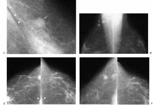 Figure 2.12 (continued)
Related posts:Stay updated, free articles. Join our Telegram channel
Full access? Get Clinical Tree
 Get Clinical Tree app for offline access

|