Clinical question
Radiograph 1
Radiograph 2
Radiograph 3
Alternative
AC dislocation
AC joint at rest
AC joint standing with weight 10 kg in the hand
Scapular Y view
Alternative US without and with cross arm test
Clavicula fracture
Clavicula PA
Clavicula AP caudocranial tilted 15°
Clavicula AP craniocaudoal tilted 15°
CT better evaluation of sternoclavicular joint
Sternoclavicular joint
Glenohumeral joint dislocation, (osteo)arthritis, proximal humerus (stress) fracture
Glenohumeral joint standing ¾ rotated to the joint
Scapula standing axial view (scapular Y view)
90 % rotated in comparison with radiograph 1
Glenoid: post reduction: axial view prone for detection of bony Bankart
CT: better detection of bony Bankart
Scapula
Scapula AP
Scapula standing axial view with elevation of humerus
CT: no superposition of ribcage
Subacromial impingement
Glenohumeral joint standing ¾ rotated to the joint
Axial view of the scapula (scapular Y view)
Glenohumeral joint, AP view prone: evaluation of subacromial space
MRA-MRI: bone and tendon evaluation
90 % rotated in comparison with radiograph 1
Sternum
Lateral view
CT
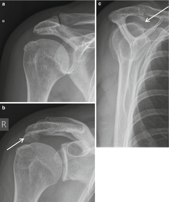
Fig. 17.1
(a–c) Radiograph of the glenohumeral joint, subacromial impingement series, including AP view (a) in prone position for evaluation of the subacromial space and AC joint, standing ¾ view of the glenohumeral joint (b) and standing scapular Y view for evaluation of subacromial spur (arrow) and acromion shape type 2 (curved) according to Bigliani
17.1.2 Ultrasound
Ultrasound is a cost-effective and accurate examination for the evaluation of the RC, SA-SD bursa, the AC joint, extra-articular and rotator interval (RI) part of the CL biceps, and other shoulder girdle muscles except for the SSC. Rutten compared the performance of US, 1.5 T C-MRI, and 1.5 T D-MRA (Rutten et al. 2010). He concluded that following US of the shoulder performed by a dedicated radiologist, MRI offers little additional value, with regard to the detection of rotator cuff tears. Personal expertise plays a crucial role in choosing which imaging technique will be used (Rutten et al. 2010) (Table 17.1). As a result of the low therapeutic consequence of non-detection of low-grade partial-thickness RC tears, US is regarded as the primary investigation tool. Advantage of US over MRI is the dynamic evaluation of impingement during elevation or endorotation. The long head tendon of the biceps (LHB) in its extra-articular course and the peripheral part of the biceps pulley and interval area is accurately demonstrated. Acromioclavicular joint capsule integrity and dislocation is evaluated in rest and dynamically during cross arm test or by compression of the lateral half of the clavicula. The glenohumeral joint is not documented on US examinations except for the joint cavity on posterior cranial approach.
17.1.3 MRI Examination Procedure
MRI is the only technique that covers all anatomic areas, including bony and soft tissue structures of the shoulder girdle.
MRA is the best technique to study the glenohumeral joint. In direct MRA (D-MRA) the shoulder joint can be approached from anterior and posterior. The posterior approach has the advantage that contrast extravasation in the anterior structures and erroneous interpretation are avoided. A small amount of iodinated contrast radioscopically to prove intraarticular needle position is followed by 10 ml Gd 1/200 solution; ready-to-use diluted Gd-DOTA solutions are commercially available (Artirem®).
I-MRA is an MR technique improving articular and periarticular contrast compared to D-MRI. It is achieved by injection of paramagnetic MR contrast media intravenously (IV). After the IV injection, exercising the joint for an average of 15 min. results in considerable signal intensity increase within the joint cavity and in pathologic tissue. The method is less invasive than D-MRA.
FS MR sequences yield arthrographic images (Figs. 17.2a–c, e and 17.3a–d). Three to the glenoid orthogonal imaging planes are used in neutral arm position (Fig. 17.3a–d and Table 17.2). ABER position (abduction and external rotation) is described by Tirman to improve detection of lesions of the anterior-inferior labral pathology, articular sided tears of the infraspinatus, and posterior impingement lesions (Fig. 17.11) (Tirman et al. 1994a, b; Cvitanic et al. 1997). Other positions may be used as there are ADIR (adduction and internal rotation) or FADIR (flexion adduction and internal rotation). FADIR positioning appears to be a useful adjunct in evaluating patients with equivocal or subtle posteroinferior labral abnormalities on conventional MRA sequences (Chiavaras et al. 2010).
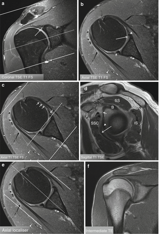
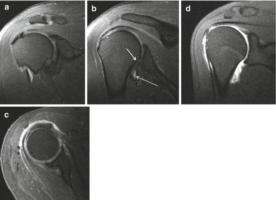

Fig. 17.2
(a–f) Three imaging planes orthogonal to the glenoid articular surface. (a) Mid-glenoid coronal image with demonstration of axial imaging plane and imaging volume perpendicular to the glenoid articular surface. (b) Axial imaging plane at the dotted line in (a). (c) Mid-glenoid axial image with demonstration of sagittal imaging plane and imaging volume parallel with the glenoid articular surface. Arrow: middle glenohumeral ligament. Short arrow: superior glenohumeral ligament. Arrowhead: anterior labrum. (d) Sagittal imaging plane at the dotted line in (c). (e) Mid-glenoid axial image with demonstration of coronal imaging plane and imaging volume parallel with the glenoid articular surface. (f) Coronal imaging plane at the dotted line in (c)

Fig. 17.3
(a–d) Comparison of 1.5 T I-MRA and 1.5 T D-MRA on T1-WI with FS in a normal shoulder joint. (a–c) I-MRA in coronal (a, b) and axial (c): gadolinium enhancement at the AC joint, glenohumeral joint with tendon sheath of CL, and SA-SD bursa. (d) D-MRA in coronal imaging plane: gadolinium enhancement at the glenohumeral joint only, axillary joint capsule insertion on humerus (b short arrow), axillary pouch of joint recess filled with gadolinium (b long arrow)
Table 17.2
Imaging sequences MRA of the shoulder
1. T1 FS para-axial slice thickness 3 mm |
2. T1 FS paracoronal slice thickness 3 mm |
3. T1 FS parasagittal slice thickness 3 mm |
4. PD and T2 FS paracoronal slice thickness 3 mm |
5. T1 parasagittal thickness slice 4 mm |
It is expected that with use of 3 T MRI or higher magnetic fields the increased contrast and spatial resolution on T2 or intermediate TE WI FS will lead to better evaluation even without gadolinium administration (Fig. 17.21a, b).
17.1.4 CT Arthrography
CTA generally is substituted by MRA (D-MRA or I-MRA). For cartilage lesions and intraarticular lesions of the biceps, an improved detection of lesions is reported. Omoumi et al. compared CTA and D-MRA with arthroscopy prospectively for hyaline cartilage lesions (Fig. 17.4a, b). They found only moderate diagnostic performance for both techniques, although better for CTA (sens 46.4–82.4 %; spec 89.0–95.9 %) compared to D-MRA (sens 31.9–66.2 %; spec 91.1–97.5 %) (Omoumi et al. 2014).
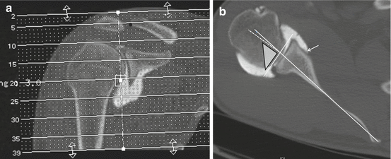

Fig. 17.4
(a, b) Glenoid version. Glenoid version is calculated on axial reconstructed multiplanar images perpendicular to the glenoid articular surface in the coronal and axial imaging plane; this is the true glenoid axial plane (a). The image inferior to the base of the coracoid process is selected (b). Tangent line to the lateral margin of the labrum is drawn, and the axis of the scapula is defined and drawn (b). A line perpendicular to the glenoid tangent is drawn (b dotted line). In retroversion negative version angles are calculated. In calculation of glenoid version. Anterior glenoid capsule insertion (b arrow)
17.2 Normal Anatomy and Variants
Normal anatomical variants have to be recognized and discriminated from relevant pathology. Variant anatomy may have a role in symptomatic shoulder complaints (Zhang et al. 2014).
17.2.1 Cartilage and Glenoid Variants
Humeral head cartilage is thicker centrally; a bare area, not covered with cartilage, is located posterior cranial at the humeral head at the junction of joint capsule and articular cartilage (Fig. 17.5a). This bare area should be discriminated from Hill-Sachs impact. Hill-Sachs lesion starts more superiorly above the level of the coracoid process on axial images. An additional bare area has been described between the supraspinatus insertion on the greater tuberosity and the adjacent articular cartilage. Failure to recognize and account for these bare areas at imaging may lead to erroneous diagnosis or overestimation of SSP partial-thickness tears (PTT).
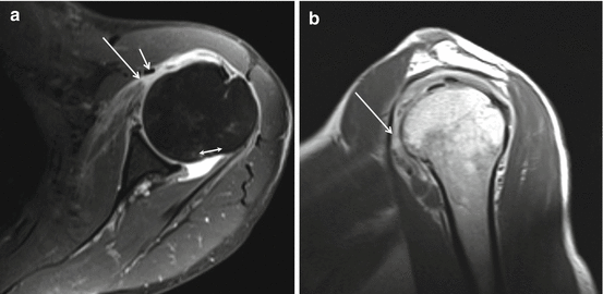

Fig. 17.5
(a, b) A 3 T I-MRA of left shoulder in patient with complaints of subcoracoidal impingement. (a) Axial T1-WI FS. (b) Sagittal T2-WI. Major expansion of the synovial space related to increased amount of synovial fluid demonstrated on (a). Bare area posterior (a double headed arrow) medial to capsular insertion not covered with hyaline cartilage. Complete SSC tendon tear (a, b arrow) with retraction medial tot the coracobrachial tendon (a short arrow)
The glenoid articular surface is located in 7° retroversion if calculated in the true glenoid axial plane (Rouleau et al. 2010). Glenoid retroversion should be calculated orthogonal to the glenoid articular surface; this is called the true glenoid axial plane. This true glenoid axial plane includes reconstructed multiplanar images with inclination in the axial and coronal imaging plane (Fig. 17.4a). If a strict axial imaging plane is chosen, retroversion is overestimated. Optimally the lateral labral margin has to be included in the glenoid tangent (this implies MRI or CTA) (Fig. 17.4a, b). Decreased retroversion leads to increased risk of anterior dislocation. The most frequent cause of reduced retroversion is Bankart lesion with or without bony fragment.
The cartilage of the glenoid is thinner centrally. The tubercle of Assaki is a central thickening of subchondral bone at the level of this cartilage thinning (De Wilde et al. 2004). Infrequently a bare spot of focal well-demarcated articular cartilage defect at the central aspect of the glenoid is present (Fig. 17.6a, b); this condition is less frequent in children.
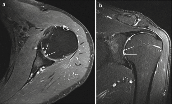

Fig. 17.6
(a, b) Normal variant, bare area humeral head, 3 T I-MRA, TSE T1-WI with FS. (a) Axial and (b) coronal mid-glenoidal imaging planes with centrally located defect at the hyaline cartilage (margins of the defect are marked with long arrows), labrum (short arrow a), labrocartilaginous junction (arrowhead b)
The glenoid can be shallow or hypoplastic predisposing to instability.
17.2.2 Labral Variants
The glenoid labrum is a ring of fibrocartilaginous tissue that surrounds the glenoid rim (Fig. 17.2d). The labrum increases the depth of the glenoid cavity, functions as a pressure seal (negative pressure) during motion, and provides stability and shock absorption to the shoulder joint. Transverse sections of the labrum reveal commonly a triangular shape (anterior 64 %; posterior 47 %) (Figs. 17.2b and 17.6a short arrows); it may be rounded (anterior 17 %; posterior 33 %) (Fig. 17.2b arrowhead) or rarely flat, cleaved, notched, or even absent (Figs. 17.7 and 17.8 arrows). The size has a broad variation from 2 to 14 mm leaving size criteria of little diagnostic use. Also the SI of the labrum is variable (Loredo et al. 1995). Initially the labrum was considered to be of low SI on all MR pulse sequences. More recent studies have identified areas of increased linear or globular signal intensity in nearly a third of arthroscopically normal labrum tissue (Table 17.3). Posterosuperior labrum increased signal is possibly related to magic angle phenomenon (B0 of 55° on 1.5 T).
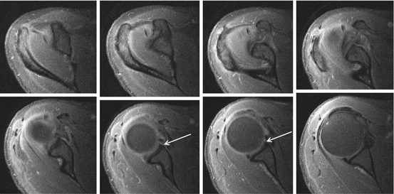
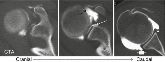
Table 17.3
Variability of SI of the glenoid labrum
Diffuse low |
Central round high SI |
Diffuse high SI |
Transverse linear high SI |
Longitudinal linear high SI |
Triangular high SI |

Fig. 17.7
Anterior labral variants: sublabral foramen documented on 3 T I-MRA. I-MRA with series of axial images superior to the glenoid up to the middle third of the glenoid. Sublabral foramen (arrow) is detected at the anterior half of the glenoid

Fig. 17.8
Anterior labral variants: sublabral foramen documented on CTA. CTA with axial images, sublabral foramen (arrow)
The superior portion of the labrum can be mobile and lax, a variant that is recognizable with arthroscopy.
The superior and anterosuperior regions of the labrum have the poorest blood supply, which slows the healing process of SLAP tears in this location.
The labrocartilaginous transition may present as an abrupt transition with the labrum demonstrating a free edge margin (type A attachment) (Fig. 17.2b, arrow) or the transition zone may blend with the hyaline cartilage (type B attachment) (Fig. 17.6a arrowhead) (Dunham et al. 2012).
17.2.2.1 Superior Labrum Variants
Fifty percent of the biceps tendon fibers arise from the superior glenoid labrum and the remainder from the supraglenoid tubercle. Three distinct types of biceps-labral complex (BLC) are recognized (Table 17.4) (Figs. 17.6b arrow and 17.2a arrow). A bicipital labral sulcus is a cleft between the labrum and the biceps.
Table 17.4
Bicipitolabral complex (BLC)
Type I BLC Labrum is firmly attached to the glenoid rim. No intervening cartilage or central free edge (Fig. 17.6b arrowhead) |
Type II BLC attachment of BLC to the glenoid occurs more medially. Continuation of the hyaline cartilage under the labrum. Accompanied by a small synovial-lined sulcus between the labral free edge and the cartilage (Fig. 17.2a arrow) |
Type III BLC prominent triangular meniscoid labrum. Deep recess that may be continuous with a sublabral foramen (Fig. 17.8) |
17.2.2.2 Anterosuperior Labrum Variants
Sublabral recess, sublabral foramen, and Buford complex are frequent variants of the anterior labrum (Kreitner et al. 1998).
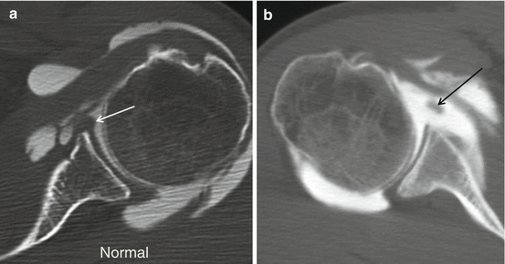
Sublabral recess (type II and III BLC) represents the most frequent normal anatomic variant of the anterior superior labrum. A recess deeper than 2 mm is present in 39 % of specimens. It follows the contour of glenoid cartilage and is smooth, with 1–2 mm width, and has no extension to superior labrum. A perilabral cyst is not present. The recess can extend posterior from the biceps tendon. Three classic key features differentiate recess from a SLAP tear (Table 17.5).
Table 17.5
Three classic key features to differentiate a sublabral recess from a SLAP tear
Location: sulcus typically extends only to the most posterior insertion point of the biceps tendon attachment to the labrum and glenoid
Contour: smooth margins: more likely sulcus. Irregularity in the contour: suspicious for SLAP tear
Orientation: extension laterally more likely tear
A sublabral foramen is detected in 10–15 % of arthroscopies and located between 1 and 3 o’clock. An associated osseous indentation is possible (Figs. 17.7 and 17.8). It should not extend below the level of the mid-glenoid notch. It can be attached to the anterior-inferior labrum through a “labral slip”: a communication between the glenohumeral joint and the subscapularis recess is found. Seventy-five percent are associated with cordlike MGHL (Buford), and a sublabral foramen may coexist with a sublabral recess. A foramen is differentiated from a labral tear or loosening based on the smooth margins of the foramen, the lack of associated traumatic injuries in the adjacent capsuloligamentous structures, and absence of significant displacement (<1–2 mm) of the detached labrum. Joint fluid that accesses to the subscapularis recess through the sublabral foramen should not be misinterpreted as a type II SLAP tear with associated paralabral cyst.
In Buford complex, which is found in 6 % of shoulder arthroscopies, the anterosuperior labrum is absent with thickening of middle glenohumeral ligament (MGHL) (Figs. 17.9a, b and 17.10a, b). If the cordlike structure is followed on consecutive axial images, the superior origin and distal capsular merge is demonstrated. An increased association of Buford complex and sublabral foramen with SLAP lesions is reported in literature. The presence of anterosuperior labral variant anatomy may result in higher stress on the superior BLC, predisposing to injury.

Fig. 17.9
(a, b) Anterior labral variants: Buford complex demonstrated on 3 T I-MRA. I-MRA with axial T1 FS images in middle third (a) and at the cranial third of the glenoid (b) demonstrating absent anterior labrum A and thick middle glenohumeral ligament (Buford complex) (arrow a, b)

Fig. 17.10
(a, b) Anterior labral variants: Buford complex demonstrated on CTA. Axial mid-glenoidal image of left normal shoulder (a) demonstrating normal anterior labrum (a arrow) and axial mid-glenoidal image of right shoulder (b) demonstrating thick middle glenohumeral ligament (b arrow) an (d) absent labrum in Buford complex
17.2.3 Glenohumeral Ligaments and Variants
The SGHL is nearly invariably present, in 97 % at arthroscopy. Variants include a common origin with the MGHL and/or direct origin from the biceps tendon. A rare variant is a SGHL origin from the posterior labrum with a course overriding the biceps tendon origin without attaching to the anterior labrum or MGHL. Normally the SGHL is rather thin but may be thickened in patients with an underdeveloped or absent MGHL. Distally the SGHL merges with the coracohumeral ligament (CHL) to form the CL biceps pulley (Fig. 17.2d small arrow). Distally the CL biceps pulley fuses with the anterior part of the SS and inserts on the greater and minor humeral tubercle and thus acts as a stabilizer of the CL biceps at the entrance of the intertubercular sulcus.
The MGHL has a variable origin, merges with the anterior capsule along SSC, and inserts on the lesser tubercle (Fig. 17.2d long arrow and c short arrows). The structure is well demonstrated if followed on continuous axial slices. It is redundant in internal rotation and stretched in external rotation and limits anterior translation in 60–90° shoulder abduction. The MGHL has a variable origin, either on labrum (Fig. 17.2c medial short arrow) or medial to the labrum (Fig. 17.4b arrow); it may have a common origin with the SGHL and biceps tendon or have a conjoined origin with the biceps tendon alone or on the IGHL. The MGHL is absent in 1/3th of the shoulders; this finding is associated with prominent subscapular recess. It may be cordlike in Buford complex with absent AS labrum (Figs. 17.9a, b and 17.1a, b). Longitudinal splitting or duplication of the MGHL has been reported as a normal variant or a partially healed longitudinal split tear of the MGHL. The foramen of Weitbrecht is located between the SGHL and MGHL (Fig. 17.8 black arrow). If the MGHL is absent, a single large communication with a redundant subscapular recess is present. A thickened and high riding MGHL may lead to narrow the foramen. A sublabral foramen may present as a pseudoparalabral cyst. The foramen of Rouvière is located between the MGHL and IGHL.
The IGHL is composed of an anterior band (“U shape”), and between those posterior band the axillary recess. It represents a fibrous thickening of the shoulder capsule and is the most consistently present and the most important stabilizator of GH joint. The anterior band runs from the mid-glenoid notch, between 2 o’clock and 4 o’clock, and is thicker than the posterior band. In ABER position (Fig. 17.11a–c arrows), the anterior band of the IGHL becomes taut and is well visualized along its entire course. A high origin anterior band should not be mistaken for an anterior labral tear on MRA. The posterior band has its origin between 7 o’clock and 9 o’clock. Two distinct patterns of humeral insertion are recognized: (1) collar-like attachment in which the entire IGHL inserts slightly inferior to the articular edge of the humeral head (Fig. 17.3b arrow) and (2) a V-shaped attachment in which the anterior and posterior bands of the IGHL attach adjacent to the articular edge of the humeral head. The axillary pouch attaches at the apex of the V distal to the articular edge.
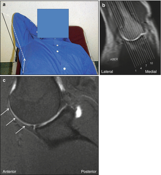
Fig. 17.11
(a–c) MRI in ABER position. (a) Prone position with shoulder in abduction and external rotation; imaging plane C is drawn. (b) Localizer image in to the glenoid coronal plane. This plane is used to plan the to the glenoid sagittal imaging plane C. (b) 1,4,7,10 slice positions in glenoid coronal plane
Variant origin of the anterior band of the IGHL from the MGHL is described; also a high origin anterior band is described and could be mistaken for an anterior labral tear on MRA. The insertion of the inferior glenohumeral ligamentous complex on the surgical neck of the humerus frequently results in a jagged appearance on axial images. The posterior band may be thicker than the anterior band. A band of connective tissue also called “the periarticular fiber system” attaches the IGHL to the SGHL (Huber and Putz 1997).
A spiral GHL arises from the axillary component of the IGHL and the infraglenoid tubercle and courses laterally to fuse with the MGHL and may be demonstrated on axial and oblique sagittal MRA planes (Merila et al. 2004).
17.2.4 Capsular Insertions
Three types of anterior capsule insertion are recognized. Type I with insertion at the glenoid margin (Fig. 17.2c medial arrow), type II inserts at the glenoid neck (Fig. 17.8 arrowhead), and type III inserts more medially along the scapula (may predispose to instability) (Fig. 17.4b arrow). Do not misinterpret over-distension of the joint capsule as a type III capsular insertion. The posterior capsule should always insert on the glenoid rim (Fig. 17.8 thick arrow)!
17.2.5 Biceps Pulleys and Rotator Interval
The biceps pulleys are the coracohumeral ligament (CHL), SGHL, and transverse ligament (TL) (Fig. 17.12a–c).
RI is the triangular space at the anteriosuperior aspect of the glenohumeral joint between the SSP and SSC tendons, the coracoid process as its base, the superior aspect of the intertubercular groove as its apex. The CHL is sometimes described as a capsular fold rather than a true ligament located at the superficial (bursal) aspect of the glenohumeral joint capsule in the RI. The lateral band (largest) inserts on the greater tubercle and merges with the SSP; the medial band (smallest) merges with the SGHL and inserts on the lesser tubercle and SSC. The SGHL runs over the scapular neck, and glenoid parallels intraarticular the course of the LHB tendon. Together with CHL it forms a U-shaped anterior sling extending along the LHB tendon that limits medial subluxation of the intraarticular LHB tendon over the edge of the lesser tuberosity (Fig. 17.12a–c) (Ho 1999; Weishaupt et al. 1999; Schaeffeler et al. 2012; Nakata et al. 2011; Tagliafico et al. 2014; Zanetti and Pfirrmann 2004).
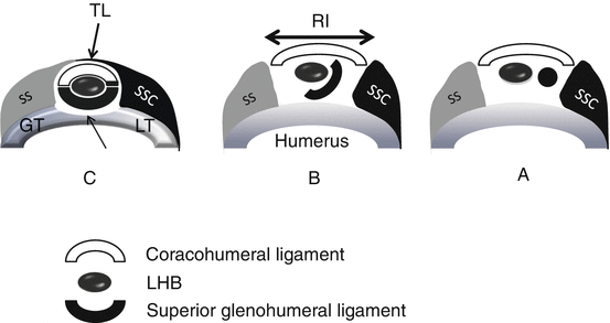

Fig. 17.12
(a–c) Schematic drawings of transverse cuts of the biceps pulley. (a) Near the origin of the ligaments at the base of the coracoid process. (b) Middle third of rotator interval (RI). (c) Lateral at the entrance of the LHB in the intertubercular groove (thin arrow), the LHB is covered by the transverse ligament (TL) that is anatomically an extension of the SSC tendon. Medially (a) the SGHL and GHL are distinct structures with separate origin at the base of the coracoid process. Centrally (b) the superior glenohumeral ligament and coracohumeral ligament fuse anteromedially to form a pulley that most laterally (c) fuses anteriorly with the minor tubercle and SSC and laterosuperior to the SSC and greater tubercle of the humerus. In this area the pulley is covered by the TL
17.2.6 Long Head of the Biceps
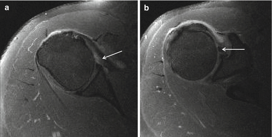
The presence of one or more supernumerary heads of the LHB tendon is described. The prevalence of a three-headed biceps brachii is estimated to be 10–20 %. The origin is located at the supraglenoid tubercle and superior labrum, the second slip adjacent to the LHB tendon origin and at the glenohumeral joint capsule, and the third slip at the margin of the greater or lesser tuberosity at the proximal aspect intertubercular groove (Vinson et al. 2012). Two separate tendons are visible in the intertubercular groove (Fig. 17.13a, b). The accessory tendon is often flat in appearance (Fig. 17.13a arrow), the adjacent LHB tendon more rounded. It is difficult or impossible to distinguish between an accessory tendon and a longitudinal tear. Features that favor an accessory tendon are the flattened appearance and most important the separate site of origin for the accessory tendon.
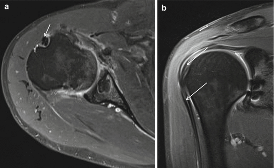

Fig. 17.13
Split long head of the biceps tendon, 3 T I-MRA. Axial T1-WI FS (a) and coronal T1-WI FS (b) showing two LHB tendons (arrows) at intertubercular groove (a, b) and superior to the groove (b)
A complete absence of the intraarticular portion of the tendon is very rare.
Variants at the anchor and proximal IA LHB variants are also known. In the absence of the normal glenoid origin, the tendon is adherent to or incorporated within the superior joint capsule. A “bifurcate” or “Y-shaped origin” of the LHB tendon is described with two separate origins that merge together before exiting the joint as a single tendon (one from glenoid, one from rotator cable or superior capsule) (Wittstein et al. 2012). Prevalence is about 2 %.
Aberrant intraarticular origin of the LHBT from the anterior edge of the supraspinatus tendon may contribute to symptomatic concomitant rotator cuff pathology; these patients are treated with tenodesis of the LHBT to relieve symptoms (Zhang et al. 2014). Possible lack of extension of intraarticular contrast material into the intertubercular groove is mostly misinterpreted as biceps tear. The clue to the diagnosis is the absence of such features as a tendon stump, tendon degeneration, and retracted distal tendon.
17.3 Pathology
17.3.1 Clavicle, AC, and Sternoclavicular Joint
Clavicle fracture and AC instability are frequent findings in contact sports and fall of bikers. Acute sternoclavicular joint subluxation/dislocation is a rare finding.
Radiography is useful for the initial assessment of suspected disorders of the clavicle, sternoclavicular, and acromioclavicular joints.
Radiographically two AP views for the clavicle and AP and scapular Y views for the AC joint are made (Table 17.1).
US has been described as a screening tool to assess possible sternoclavicular joint dislocation; however, it is usually used only if CT and MRI are not readily available.
AC joint instability is graded by Tossy-Rockwood in six types (Table 17.6). US to grade AC joint instability is as reliable as radiographic measurement (Kock et al. 1994; Heers and Hedtmann 2005, Tossy et al. 1963; Rockwood et al. 1996). Disrupted deltoid and trapezius insertion and common fascia were demonstrated on US in all patients classified according to Rockwood’s classification as type V, half of the patients classified as type IV, about a quarter of patients classified as type III, and only in a minority type II injuries (Table 17.6).
Table 17.6
Tossy-Rockwood classification AC instability
Type I | Type II | Type III | Type IV | Type V | Type VI (rare) | |
|---|---|---|---|---|---|---|
AC ligament | I–II | III | III | III | III | III |
CC ligament | 0 | I–II | III | III | III | III |
Joint capsule | 0 | III | III | III | III | III |
Deltoid muscle detachment | 0 | II | III | III | III | III |
Trapezius muscle detachment | 0 | II | III | III | III | III |
Clavicle (radiograph, US) | Not elevated with respect to acromion | Minor elevation with respect to acromion | Elevation of one clavicula height with respect to acromion | Clavicle displaced posteriorly into trapezius | Coracoclavicular distance more than double than normal (>25 mm) | Clavicle inferiorly displaced behind coracobrachialis and biceps tendons |
Although US is increasingly used as a primary investigation tool to demonstrate AC dislocation in a dynamic way (during cross arm test or with compression of the clavicle), it has a limited role in the evaluation of the AC joint itself, where it is most useful to exclude the presence of joint inflammation with increased joint fluid and Doppler signal (Heers and Hedtmann 2005; Matter et al. 1995). If joint fluid is detected on US, it is considered a nonspecific finding, which could represent active inflammation or simply joint effusion due to degenerative osteoarthritis.
CT allows excellent visualization of the articular surfaces, osseous changes, subtle or complex fractures, and joint malalignment, with a rapid scan time, making it particularly helpful in the workup of trauma patients. With its multiplanar capabilities and superior soft tissue resolution, MRI is a very effective modality for characterizing soft tissue injuries, inclusive of ligamentous tears and cartilaginous injuries. In the specific case of posterior sternoclavicular dislocations, both CT and MR angiography can be very helpful in elucidating occult associated vascular injury (Ernberg and Potter 2003).
Radiographs, CT, US, and MRI may show widening of the AC joint space in painful traumatic and even atraumatic stress-induced distal clavicular osteolysis (DCO). Cutoff width of the normal AC joint is <5 mm; right and left differ by no more than 2–3 mm. Atraumatic DCO has been described in adult athletics. The combination of weightlifting and overhead activity (basketball, volleyball, tennis, swimming) is a risk factor for atraumatic DCO. Long-term sequelae DCO include widening of the AC joint and AC joint osteoarthritis. About 80 % of patients present with flattening of the distal clavicle and interval widening of the AC joint to a mean of 5.0 mm (Cahill 1982; de la Puente et al. 1999; Kaplan and Resnick 1986; Murphy et al. 1975; Levine et al. 1976; Roedl et al. 2015). Posttraumatic and stress-induced DCO have similar appearances on MR imaging, the most common and conspicuous MR imaging feature being increased T2 signal intensity in the distal clavicle (Kaplan and Resnick 1986).
17.3.2 Glenohumeral Instability, Microinstability, and Internal and External Impingement
17.3.2.1 Labral Pathology
Labral pathology is found in athletes with instability and in repetitive microtrauma and trauma and related to aging and degeneration. Degenerative labrum lesions are characterized by mucoïd degeneration, calcifications, synovialization with alterations in morphology, and SI of the labrum (Loredo et al. 1995). The abnormal morphology should be described with possible fraying, absence, detachment, displacement, fragmentation, deformity, or flap tear.
17.3.2.2 Shoulder Instability
The shoulder joint is the most unstable joint. The etiology of instability can be traumatic or atraumatic. Instability is classified according to the severity (microinstability, subluxation, and dislocation) and according to the direction (unidirectional–multidirectional).
Macroinstability is most often anterior (90 %) and much less frequent posterior (5 %), rarely inferior (luxatio erecta) or superior. Superior dislocation resembles RC rupture. Associated fractures and labroligemantous lesions should be excluded. After traumatic shoulder dislocation (treated non-operatively), the likelihood of repeat dislocation depends on patient age and the date of the initial injury. Patients younger than 20 years have a higher risk of recurrent dislocation (>90 % when subluxation events are included) than those older than 40 years (<10 %).
Multiple categories of microinstability are described. AMBRII (atraumatic, multidirectional, bilateral, responds to rehabilitation, inferior capsular shift, interval closure) is found in young females and present with capsular laxity or hypoplastic glenoid labrum. TUBS is traumatic unidirectional instability after Bankart surgery. AIOS is acquired instability related to overuse with surgical repair and often found in athletes doing throwing sports or swimming.
Shoulder dislocation is primarily investigated with radiographs and trauma series (Fig. 17.14a, b and Table 17.1). Secondarily MRA or CTA is performed for the evaluation of labrum, ligaments, tendons, and cartilage.
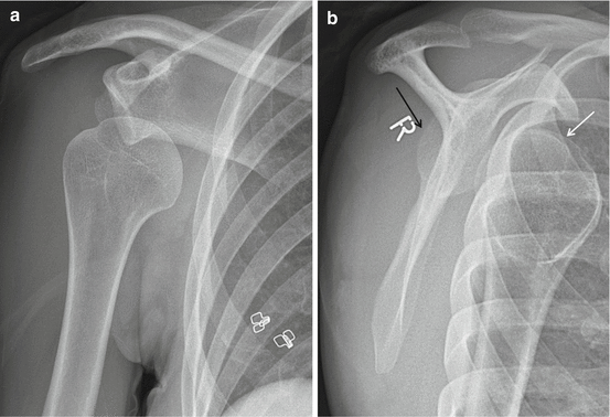

Fig. 17.14
(a, b) Acute right anterior shoulder dislocation in a 30-year-old female patient. Radiographic evaluation with trauma series (same patient of Fig. 17.15). (a) ¾ view axial to the glenoid demonstrating inferior medial dislocation of the humerus head. (b) Scapular Y view with anterior dislocation of the humerus (white arrow) relative to the glenoid (black arrow)
17.3.2.3 Anterior-Inferior Labrum Lesions
Anterior-inferior capsuloligamentous, labrum, and glenoid lesions are related to anterior shoulder dislocation and may lead to habitual dislocation and shoulder instability.
Bankart lesion is a detachment of anteroinferior labrum and IGHL from the glenoid rim with rupture of the periosteum but no cartilage damage (Fig. 17.15).
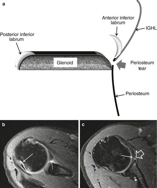
Fig. 17.15
(a–c) Bankart lesion in a 30-year-old female patient with traumatic right shoulder dislocation (same patient of Fig. 17.14). (a) Schematic drawing of axial slice through the inferior third of the glenoid with Bankart lesion. Displacement of anterior-inferior part of the glenoid labrum with disruption (thick arrow) of the periosteum connecting the labrum with the glenoid. Normal IGHL connection to the labrum and periosteum. (b) Axial 3 T I-MRA T1-WI FS at the level of the tip coracoid process with Hill-Sachs depression (arrow) (sublabral foramen thin arrow). (c) Bankart lesion with gadolinium enhancement between labrum and hyaline (arrow) cartilage extending lateral to the labrum with infiltration of extra periosteal area (arrowhead)
In bony Bankart lesion a bone fracture fragment at the anterior-inferior part of the glenoid is present (Fig. 17.16). The size of the fracture fragment defines the grade of instability; fracture fragments involving 1/3th or more of the AP diameter of the glenoid are at risk for development of habitual dislocation and need Bankart repair surgery, The diameter of the bone fragment is best evaluated on CT(CTA).
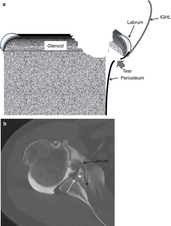
Fig. 17.16
Bony Bankart lesion in a 35-year-old male patient with history of acute right shoulder dislocation. (a) schematic drawing of axial slice through the inferior third of the glenoid with bony Bankart lesion. Demonstration of loose bony fragment and torn and partially stripped periosteum. (b) Axial CTA image at the level of the inferior third of the glenoid. Fracture line at the glenoid with step of at the subchondral bone (dotted arrow) and medial displacement of the fracture fragment (star) including the labrum (arrow). Contrast enhancement of the periosteum related to disruption of the periosteum (short arrow)
Multiple acronyms are known to describe non-bony Bankart-type lesions of the anterior-inferior labrum related to anterior traumatic shoulder dislocation. For some surgeons differentiating the lesions is important to plan therapy and to prepare surgical intervention.
Glenoid labrum ovoid mass (GLOM) is defined as a detached labrum that floated upward in the region of the coracoid process. GLOM may simulate another lesion, biceps dislocation, loose body, air, cordlike MGHL, or SLAP. In the differential diagnosis the detection of an anterior-inferior labrum lesion is important.
Perthes lesion is defined as an avulsion of the IGHL and labrum with intact periosteum; the intact but stripped periosteum connects to the IGHL (Fig. 17.17a, b). Perthes lesions are better visualized in ABER position.
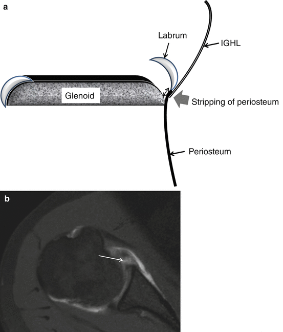
Fig. 17.17
(a, b) Perthes lesion schematic drawing and 1 T D-MRA axial T1-WI. Displacement of the anterior-inferior labrum continuous with the IGHL and stripped periosteum (double-sided dotted arrow) but no disruption of the periosteum. Gadolinium enhancement between hyaline cartilage and labrum without disruption of the periosteum (arrow). Anterior extra-articular location of gadolinium related to anterior capsule tear
Anterior labroligamentous periosteal sleeve avulsion (ALPSA) is described by Neviaser (1993); an avulsion of the IGHL complex from glenoid with intact periosteum is found. The avulsed labrum is medially displaced and inferiorly rotated (Fig. 17.18a, b). If the lesion heals in this position with synovialization, a mass is created and recurrent anterior instability is characteristic. In chronic cases the surgeon has to dissect the lesion from the scapular neck to relocate the labrum on the glenoid rim. ALPSA can also be found at 6 o’clock.
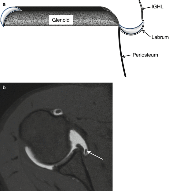
Fig. 17.18
(a, b) ALPSA lesion schematic drawing and 1 T D-MRA axial T1-WI. Avulsion of the inferior glenohumeral ligament complex from the glenoid with intact periosteum and medially displaced and inferiorly rotated labrum (b arrow)
In anterior ligamentous periosteal sleeve avulsion (ALIPSA), the IGHL is partially disrupted from the labrum without labrum displacement (Fig. 17.19).
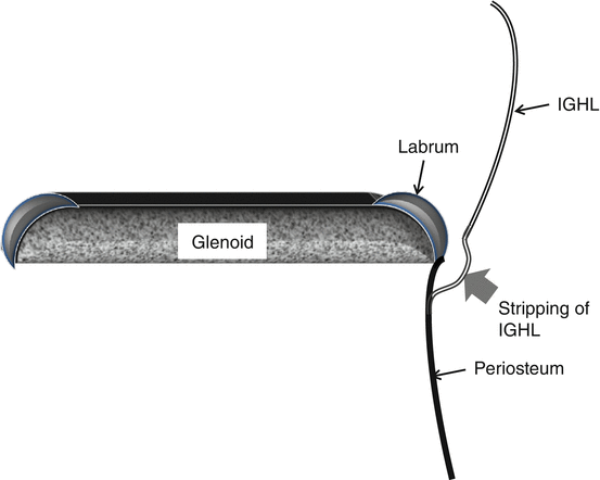
Fig. 17.19
ALIPSA lesion schematic drawing
Glenolabral articular disruption (GLAD) is a non-displaced superficial tear of the anterior-inferior labram with fibrillation (flap) or erosion (defect) of the adjacent articular cartilage (Fig. 17.20a–c thin arrows). Usually no associated dislocation nor anterior instability is present (anterior fibers of IGHL not disrupted, labrum not displaced). This type can progress to rapid degenerative joint disease and intraarticular bodies. Treatment is debridement of the labrum and cartilage lesion without stabilization procedure.
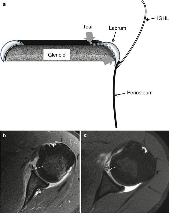
Fig. 17.20
(a–c) GLAD schematic drawing and 3 T I-MRA of left shoulder in a 19-year-old male patient, for comparison 1 T D-MRA. (b) Axial T1-FS 3 T I-MRA and (c) axial T1-FS 1 T D-MRA image demonstrating gadolinium enhancement at the hyaline cartilage (arrow) continuous within the labrum. No dislocation of the labrum
In humeral avulsion of the IGHL (HAGL) the normal U shape (Fig. 17.3b thin arrow) of the anterior band of the IGHL becomes J-shaped (Fig. 17.21a, b). A not-recognized HAGL is a cause of a failed Bankart repair.
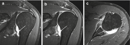
Fig. 17.21
(a–c) A 3 T I-MRA of HAGL lesion in a 44-year-old male patient after trauma of the left shoulder. (a) Coronal intermediate TE WI FS, (b) coronal T1-WI FS, and (c) axial T1-WI FS demonstrating J aspect of axillary pouch on coronal imaging signifying loosening of the humeral insertion of the inferior glenohumeral ligament (arrows). Associated extensive labral lesion is depicted with GLAD morphology anteriorly and posteriorly (PGLAD) (c thin arrows). Demonstration of interchangeable images with equal spatial resolution and contrast on intermediate FS (a) and T1 FS (b)
In 20 % of cases bony avulsion of humerus is present; these lesions are given the acronym BHAGL.
Glenoid articular rim disruption (GARD) (divot) is a chondral or osteochondral lesion adjacent to a labral tear (Bankart, Perthes, ALPSA, etc.) with associated dislocation and instability on clinical examination (Fig. 17.22a–c). The lesion is treated with labroligamentous repair.
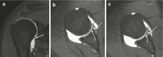
Fig. 17.22
GARD lesion on 1 T D-MRA T1 FS. (a) Coronal and (b, c) axial images. Hyaline cartilage lesion (arrows) with Perthes lesion (thin arrows) demonstrated on axial images
Lesions may deteriorate in time. Perthes can change in Bankart or ALPSA. Labral lesions associated with inferior glenohumeral ligament complex lesions cause major instability (HAGL and BHAGL).
Glenoid avulsion of the IGHL (GAGL) is rare; characteristic is the inverted J sign.
In floating AIGHL and avulsion of the humeral and glenoid, attachment of the IGHL is present. The condition is more frequent in younger patients and coincides with Hill-Sachs lesion.
Midportion capsular tear accounts for 35 % of capsular tears and is located more posterior and often found after initial dislocation without labral tear. The lesion can be confused with contrast extravasation.
17.3.2.4 Adhesive Capsulitis
Adhesive capsulitis (frozen shoulder) is a clinical syndrome predominantly found in middle-aged females (40–60 years). The lesion is frequently underdiagnosed. Corticosteroid injections offer rapid pain relief in the short term (particularly in the first 6 weeks) for adhesive capsulitis. Long-term outcomes seem to be similar to other treatments, including placebo (Song et al. 2014). On MRI, I-MRA, and D-MRA the axillary pouch is small with thickening (>4 mm) of the capsule and IGHL and enhancement after IV Gd (Figs. 17.23 and 17.24). Due to capsule enhancement I-MRA offers increased conspicuity of thickening of the axillary capsule and IGHL compared to D-MRA and MRI. Real-time and dynamic US has a role in diagnosis of retractile capsulitis. Reduced endo- and exorotation capacity of the glenohumeral joint results in constant anterior location of the LHB and the intertubercular groove. Thickening and power Doppler signal of the synovium and capsule may be present at the LHB tendon sheath or at the RI (Corazza et al. 2015). Therapeutic imaging (US or CTA) guided joint distention with corticosteroid may be performed.
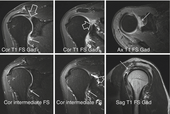
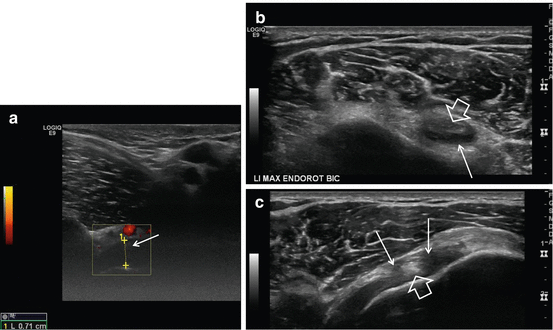

Fig. 17.23
Adhesive capsulitis, 3 T I-MRA in a 67-year-old male patient. SLAP VIII lesion. Demonstration of thickening of the axillary capsule-IGHL (arrows) and rotator interval (thin arrow). Better demonstration on T1-FS compared to intermediate FS images. SLAP VIII lesion is demonstrated with paralabral cyst (thick arrows)

Fig. 17.24
Adhesive capsulitis, US in a 48-year-old female. (a) Axillary image with shoulder elevation, (b) axial slice at the level of the LHB tendon sheath, and (c) axial image at the RI with maximal endorotation. Thickening of the capsule and synovium (arrows) with anterior location of the LHB (thick arrow) on maximal endorotation position
17.3.2.5 Posterior Instability
Posterior instability accounts for 5 % of instabilities. It is characteristic non-traumatic event that may cause recurrent posterior instability. The instability is multidirectional and related to seizures, electric shock, or adduction, flexion, and internal rotation movement. In 60 % labral lesions are present. Posterior labral tears greater than 15 mm are significantly associated with posterior instability. Posterior capsular laxity is the most common abnormality (Schwartz et al. 1987).
The dislocation may result in reversed Bankart lesion with labral tear and periosteal rupture but without cartilage lesion. Bone fracture fragment may be present as well as a reversed Hill–Sachs (McLaughlin). Fluid or contrast may extend behind the glenoid.
In Kim lesion deep intrasubstance incomplete detachment (marginal crack) of the posteroinferior labrum is associated with a defect at the chondrolabral junction. MRI depicts these lesions in a sensitive (85 %) and specific (75 %) way (Smark et al. 2014). This may lead to repetitive posterior instability with subluxation of the humeral head and shear forces between glenoid rim and labrum with failure of the chondrolabral junction. Kim lesion can be concealed at arthroscopy and is treated by converting it to complete tear and suture with an anchor.
Reversed or posterior Perthes (Fig. 17.25) may lead to POLPSA or posterior labroligamentous periosteal sleeve avulsion (posterior ALPSA) (when medially displaced) and predisposes to posterior instability (Fig. 17.26). This lesion is treated by reduction of the periosteal sleeve with attachment of the labrum.
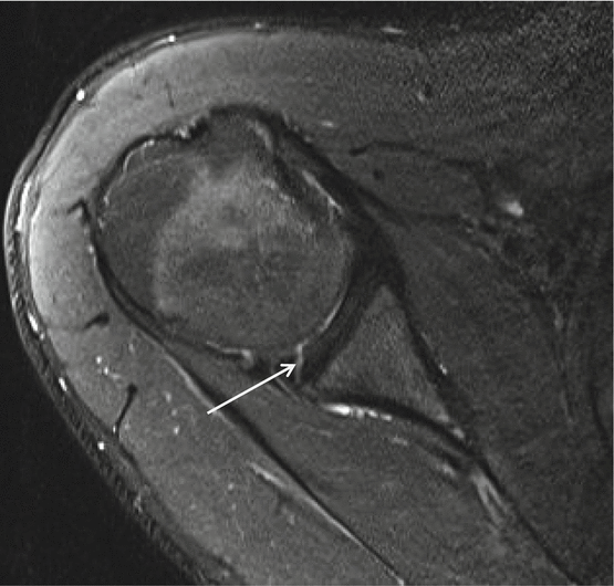
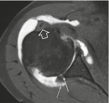
Fig. 17.26
POLPSA 1 T D-MRA, older patient with glenohumeral osteoarthritis. Less conspicuous enhancement at the posterior inferior labrum (arrow). Chronic tenosynovitis LHB with stenosis: absence of contrast at tendon sheath, thickening of tendon sheath (thick arrow). Posterior capsule insertion (thin arrow)
In posterior glenoid labrum articular disruption (GLAD), a focal defect in the articular cartilage between 7 and 9 o’clock is present associated with labral tear but no instability.
Stay updated, free articles. Join our Telegram channel

Full access? Get Clinical Tree


