- •
Conventional gamma cameras use one to three detectors, based on a NaI scintillation crystal and a photomultiplier tube array, that rotate around the patient.
- •
Cameras commonly use parallel-hole collimators for which sensitivity is constant, but spatial resolution degrades as the distance from the collimator increases.
- •
New cardiac SPECT designs use a variety of techniques, including CZT semiconductor detectors, novel collimators, and large numbers of detectors to increase sensitivity.
- •
Compared with conventional cameras, new cardiac SPECT systems have four to eight times the sensitivity and similar or improved spatial resolution.
- •
3D SPECT images are reconstructed from a set of 2D projection data using the FBP algorithm or iterative reconstruction.
- •
Important factors that degrade image quality are gamma ray attenuation and scatter; spatial-resolution loss, which increases with increasing distance from the collimator; patient motion; and image noise.
- •
Iterative reconstruction provides a mechanism to correct for the effects of attenuation, scatter, and collimator resolution losses.
- •
Attenuation correction requires a spatially registered transmission map of the patient tissues, which is most commonly acquired with a CT scan.
- •
Noise in the acquired projections is Poisson distributed, which means that the variance (σ 2 ) in the number of gamma rays detected in a pixel is equal to the number of detected gamma rays (N): σ 2 = N.
- •
Using ECG gating divides the detected gamma rays into separate projection data sets (8 to16 data sets for SPECT and up to 32 data sets for planar imaging) based on the time that has passed since the most recent R-wave of the ECG signal.
- •
ECG gating decreases image blurring caused by cardiac contractile motion (but increases image noise) and provides information on cardiac function (e.g., ejection fraction and wall motion).
- •
Cardiac SPECT instrumentation continues to evolve with ongoing research into the development of dynamic SPECT imaging and respiratory motion correction.
Introduction
The modern gamma camera traces its origins back to the design introduced by Hal Anger in 1958. , Since then, camera instrumentation has undergone a slow evolution that has continuously improved both its performance and capabilities. Rotating gantry systems have allowed for three-dimensional (3D) single photon emission computed tomography (SPECT) in addition to two-dimensional (2D) planar imaging. The use of multiple detector heads has improved the sensitivity (i.e., detection efficiency) of cameras and reduced scan times. Gating based on the electrocardiogram (ECG) has provided information on cardiac function. Advanced iterative reconstruction algorithms have improved image quality and provided a means to compensate for degrading factors, such as photon attenuation and scatter. More recently, new detector technology has led to the development of novel camera configurations that are further increasing sensitivity and temporal resolution. This chapter provides a brief overview of the hardware and software used to create cardiac SPECT images.
Detectors
SPECT imaging provides a picture of how radiotracers (tracers labeled with a radioactive isotope) are distributed in a patient’s body. The radioisotopes produce high-energy gamma rays that are invisible to the naked eye and so special radiation detectors are required to detect them. Each detector provides information about the energy and position of a detected gamma ray. Important detector characteristics that influence image quality are the detector efficiency, which is the number of incident gamma rays that are detected; the energy resolution to discriminate against scattered and background radiation; and the intrinsic spatial resolution to locate the position of the detected event on the detector surface. Detectors in cardiac SPECT are based on either scintillation or semiconductor materials.
Scintillation detectors
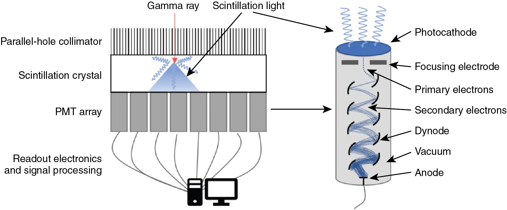
The most commonly used detector material is the scintillation crystal that converts energy from each gamma ray (high-energy photon) into many low-energy photons, which are subsequently converted to an electronic signal using a light sensor ( Fig. 1.1 ).
Scintillation crystals
Scintillation materials emit light (low-energy photons) when they interact with gamma rays. Desirable features in a scintillator are a high density to ensure a high efficiency for interacting with gamma rays, a high light yield (number of information carriers), good transparency to those photons to ensure a high energy resolution, and a fast response to process each event quickly to be ready for the next interaction (low dead time). Most SPECT scintillation detector–based systems use sodium iodide (NaI) inorganic ionic crystals or, less commonly, cesium iodide (CsI) crystals. NaI crystals yield 41,000 photons per gamma ray MeV, whereas CsI crystals yield 64,000 photons per MeV. High numbers (N) of scintillation photons are desirable because the gamma ray measurement uncertainty σ is governed by Poisson counting statistics for which σ 2 is proportional to N.
Light sensors
Scintillation detectors produce an electronic signal proportional to the energy of each gamma ray by coupling a light sensor to the scintillation crystal. A photomultiplier tube (PMT) is a light sensor that contains a photocathode and series of dynodes (see Fig. 1.1 ). The photocathode absorbs scintillation photons and relays their energy to ionized electrons. These primary electrons are focused onto the first dynode in the PMT where their kinetic energy ionizes secondary electrons. Electric fields within the PMT accelerate the resulting electrons through a series of dynodes under a vacuum. The number of electrons is increased approximately five-fold after each interaction with a dynode. With 8 to 12 dynodes in a typical PMT, the total signal amplification is approximately 10 6 or 10 7 . The electrical signal read from the back of the PMT is proportional to the amount of incident scintillation light, which is, in turn, proportional to the energy of the detected gamma ray. The PMT signal is, therefore, calibrated to provide a measurement of the gamma ray energy.
For some applications, solid-state light sensors are desired. Avalanche photodiodes (APDs) are silicon-based semiconductors across which a high electric field (>10 7 V/m) is used. Inbound photons liberate an electron in the material to which the electric field provides enough energy to produce an additional electron-hole pair. Subsequent electrons are also accelerated to create more electron-hole pairs. This signal amplification is known as the avalanche effect . Increasing the electric field increases the amount of amplification. The electronic signal obtained from an APD, whose electric field is set to generate an avalanche, is proportional to the number of scintillation light photons detected. APDs are typically around 2 mm thick and have an area up to 30 mm × 30 mm. Higher electric fields lead to an uncontrolled avalanche, allowing APDs to be used like a Geiger-counter such that the signal is independent of the number of photons that interact within the time it takes the detector to reset. Silicon photomultipliers (SiPMs) use arrays of a lot of very small area APDs (side length of 20 to 100 μm) in Geiger-mode to count the number of interacting light photons. The electron signal obtained from a SiPM is proportional to the number of APD cells activated, which is proportional to the number of scintillation light photons, which is, in turn, proportional to the energy of the detected gamma ray. The detectors must be calibrated to the specific expected gamma ray energy. This is important because, for higher gamma energies, there is an increased potential for event pile-up, which is when more than one scintillation photon interacts with an APD cell that can only count one photon at a time. Event pile-ups produce less APD cell activations than there are scintillation photons which can lead to the underestimation of gamma ray energy.
Most clinical SPECT systems use PMTs; however, some small animal systems or evolving research cameras may employ APDs or SiPMs. Solid-state light sensors are much smaller than PMTs, allowing for compact camera designs. When used with appropriate electronics, they can also be used in magnetic fields to enable the development of hybrid SPECT–magnetic resonance imaging (MRI) cameras, which is something that is not possible with PMTs.
A scintillator paired with a PMT produces around 10 information carriers per keV of gamma ray energy. With a scintillator and solid state light sensor, around 29 carriers are produced per keV, allowing for improved energy resolution.
Position of interaction
The scintillation light from the detector crystal spreads from the point where the gamma ray interacts with the crystal. The spreading light shower illuminates more than one light sensor and the amount of light seen by a light sensor depends on its distance from the point of interaction. Using the known positions of the light sensors and a weighted combination of the signals measured by each, the location of the point of interaction of the gamma ray with the scintillation crystal can be calculated. The energy and location of the detected gamma ray are recorded and used to build up a 2D picture, also known as a “projection,” of the distribution of the radioisotope in the patient.
Cadmium zinc telluride detectors
Cadmium-zinc-telluride (CdZnTe or CZT) semiconductor detectors directly convert gamma rays into electronic signals. CZT material is sandwiched between a front cathode and an array of pixelated anodes at the back surface. Incoming gamma rays ionize the CZT material to create e-h pairs within the detector. A high voltage is applied across the detector to collect electrons at the anodes. The voltage is set high enough to minimize recombination of electrons with holes, which could result in lost signal and a perceived reduction in the energy of the detected gamma ray. Nevertheless, it is not chosen to be high enough to induce Geiger breakdown like SiPM light sensors do. Thus, the charge collected at an anode is assumed to be proportional to the energy of the detected gamma ray. The single step conversion of gamma ray energy produces around 333 information carriers per keV. Even with some lost signal from charge recombination or lateral drift of charges to spread the signal between anodes, the energy resolution of CZT detectors (6% at 140 keV) is much better than that of scintillation detectors (10% at 140 keV for NaI-PMT). ,
Collimators
Gamma rays from radiotracers in the patient spread out in all directions such that a 2D image formed on a bare detector would be irrevocably blurred. To provide a clear 2D view, we need information about the trajectory of the detected gamma rays. Collimators provide this context by restricting the angle of the gamma rays that are allowed through to the detector. With a collimator mounted to the surface of a detector, the gamma rays that are detected are known to have traveled a path within a narrow range of angles.
Parallel hole collimaters
Parallel-hole collimators allow for the detection of gamma rays traveling perpendicular to the detector surface. The collimator has a densely packed array of parallel holes in a high-density material. The diameter of the holes, spacing between holes, and collimator thickness (or hole depth) dictate the resulting spatial resolution and the sensitivity for detecting gamma rays. Fine detail (better spatial resolution) is provided by thick collimators with small-diameter holes. This arrangement, however, drastically limits the number of gamma rays detected from a source. In cardiac imaging, low-sensitivity collimators can mean needing higher patient doses or longer imaging times to acquire sufficient counts. Conversely, when using large holes or thinner collimators, the sensitivity is improved but at the cost of a blurrier image ( Fig. 1.2 A). Collimators are described based on the energy of the isotopes they are designed to detect (isotopes used in cardiac SPECT are typically low energy) and their sensitivity/resolution. A common collimator for cardiac imaging is the low-energy high-resolution (LEHR) collimator.
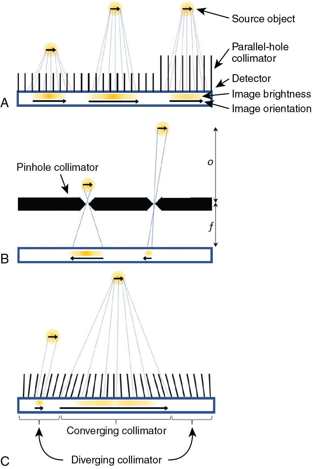
The sensitivity for detecting gamma rays is approximately uniform for varying distances of sources from a parallel collimator. The spatial resolution degrades linearly with distance of the source from the plane of the detector so that an object close to the detector-collimator will be resolved more clearly than an object farther away (see Fig. 1.2 A).
Pinhole collimaters
A pinhole collimator has a single hole. Detected gamma rays that have passed through the aperture produce an inverted image of their source (see Fig. 1.2 B). Depending on the ratio of the pinhole-to-detector and detector-to-source distances, the image can either be magnified or minified. Magnification is particularly helpful for small animal imaging systems, whereas minification can allow small-detector-area cameras to avoid truncation of the heart in dedicated cardiac imaging. The spatial resolution of a pinhole collimator-detector depends in part on the aperture diameter and the amount of magnification. The sensitivity for detecting gamma rays depends on the diameter of the pinhole aperture but also on the distance and angle of the source with respect to the pinhole. The sensitivity can be very high for sources close to the pinhole but decreases for gamma rays incident from wider angles and for sources at greater distances. Like the parallel-hole collimator, spatial resolution degrades linearly with distance of the source from the pinhole.
Multifocal collimaters
Multifocal collimators are used for specialized applications to improve both sensitivity and resolution compared with traditional parallel-hole collimators using a combination of converging and diverging holes with various focal lengths in a single collimator (see Fig. 1.2 C). The design most relevant to cardiac imaging has holes at the center of the collimator that converge toward the heart and therein sample the heart location more for improved sensitivity and magnify the heart onto the detector for improved resolution compared with parallel hole collimators. Holes closer to the edges of the collimator diverge more the closer they are to the edge until they are nearly parallel, which provides information about surrounding structures and avoids truncation artifacts.
System designs for cardiac SPECT imaging
Rotating gamma cameras
The conventional camera design for SPECT imaging uses a scintillation detector head, with a parallel-hole collimator, attached to a gantry, which allows the detector to be rotated around the patient to acquire multiple different views ( Fig. 1.3 A). The patient lies on a table near the center of rotation of the system and is the axis about which the detector is rotated during acquisition. The axial field-of-view (FOV) of modern SPECT cameras is usually about 40 cm, completely covering the heart. The table and patient thus remain stationary during the entire SPECT acquisition. The orientation of the patient is usually either supine or prone on the table with the axis of rotation of the camera perpendicular to the transverse plane of the patient.
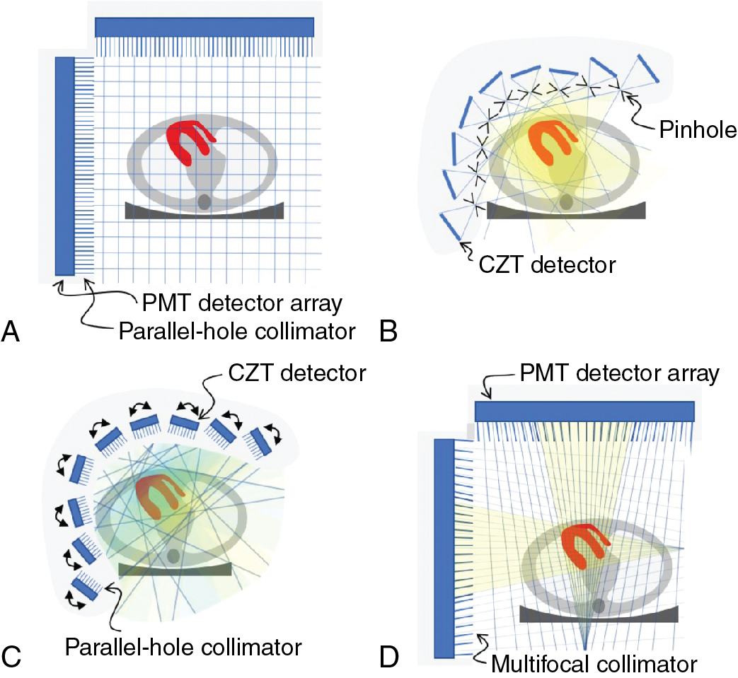
A 3D image of the radioisotope distribution can be created from a set of 2D images taken over a range of angles around the patient through image reconstruction. To accurately and consistently move the detector around the patient, it is mounted on a motorized rotating gantry ring. As it rotates, the detector head can also be moved in or out to optimize the distance of the detector from the patient. Most commonly, a parallel-hole collimator is used for which resolution gets worse with increased patient-to-detector distance, so the detector is kept as close to the patient as possible.
With a single-head gamma camera, only one view is acquired at a time. Adding additional detector heads to the gantry allows for the acquisition of multiple views simultaneously and so increases the sensitivity of the system. Cameras with two detector heads are common, and three-head systems are also available. The acquisition orbit of the camera is usually from left posterior oblique (LPO) through the left anterior oblique (LAO) to right anterior oblique (RAO) position. A 180-degree arc of views is needed for 3D image reconstruction and, because the heart is located on the left side of the body, the LPO-to-RAO rotation provides the lowest attenuation by the patient tissues and thus the strongest signal from the myocardium. Using a two-head system with the heads 90-degrees apart allows the full 180-degree data set to be acquired with a single 90-degree rotation of the camera.
One additional feature available on some cameras is the ability to tilt the detector in the caudal direction. This feature is sometimes helpful to allow for the acquisition of true short-axis (SA) views during ECG-gated blood-pool planar studies.
Dedicated cardiac systems
In addition to the conventional general-purpose gamma camera, a number of novel camera designs are now available for cardiac SPECT imaging. The two most popular of these dedicated cardiac cameras both use the same CZT-based detector module but with a quite different number and arrangement of the modules.
The multipinhole camera (Discovery NM530c, GE Healthcare) uses a set of 19 detectors. Each detector consists of four CZT-modules arranged in a 2 × 2 array to create a square 8 cm × 8 cm panel. The detectors are aligned on three parallel arcs around the patient (from LPO to RAO) with nine detectors in the central arc ( Fig. 1.3 B) and five detectors each on the inferior and superior arcs. Each detector uses a single-pinhole collimator and the 19 pinholes all focus on a common point. By centering the patient’s heart within the 19-cm diameter FOV, the system provides a fourfold sensitivity gain over a conventional dual-head gamma camera. The system design uses the minifying properties of the pinhole collimator to ensure the image of the entire heart fits within the size of the detector.
A second dedicated cardiac design (DSPECT, Spectrum Dynamics) uses nine column detectors ( Fig. 1.3 C Each detector consists of a 1 × 4 array of CZT modules and is 4 cm in the patient transverse direction and 16 cm in the axial direction. The columns oscillate during acquisition to fan over the entire FOV in a period of 3 to 6 seconds. A short prescan is used to define the position of the heart. During the full scan, the columns oscillate nonuniformly, spending more time directed at the heart but still providing some information about the rest of the patient as well. Each detector uses an ultrahigh-sensitivity parallel-hole collimator that is matched and aligned with the 2.5-mm detector pixels. The large collimator bore diameter causes a loss in spatial resolution, but this resolution loss is recovered by careful modeling of the collimator during image reconstruction. The raw sensitivity gain of the system is 8 to 10 times that of a dual-head conventional camera. Another innovation of the DSPECT system is that it uses a patient chair so that the patient is imaged in an upright position, rather than the conventional supine position. The chair can also be tilted to allow for semireclined imaging, which provides a second patient orientation and helps to assess for attenuation artifacts.
A third approach to cardiac imaging uses a conventional dual-head gamma camera but with a specially designed multifocal collimator and acquisition protocol (IQ SPECT, Siemens , ). The multifocal collimator is configured as a converging collimator in the center of the detector, but the focal length increases with increasing distance from the center so that by the edge of the detector, it is behaving like a parallel-hole collimator ( Fig. 1.3 D). This design has increased the sensitivity in the center and reduced sensitivity toward the edges of the detector FOV. Using a cardiocentric orbit that maintains the position of the heart near the most sensitive position for the collimator and careful modeling of the collimator during reconstruction to correct the spatial distortions caused by the collimator allows for the reconstruction of images that have similar resolution but a fourfold increase in sensitivity over conventional dual-head cameras.
Factors affecting image quality
Many different factors can influence the quality of cardiac SPECT images and degrade the accuracy of cardiac imaging. Some are related to patient physiology, such as consumption of caffeine or ability to reach target heart rate during exercise, whereas others are addressed by quality assurance programs that ensure optimal camera performance and proper radiotracer formulation. Four factors that are always present with SPECT imaging are attenuation, scatter in the patient tissues, patient motion, and noise in the detected data. Please also see the discussion in Chapter 5 .
Attenuation
When the radioisotope of the tracer in the myocardium decays, it emits gamma rays. For 99m Tc-labeled tracers, the primary emission is a gamma ray with 140 keV. Although many gamma rays pass unimpeded out of the patient, a substantial number interact with the patient tissues. The interaction can be a photoelectric absorption wherein the gamma ray is completely absorbed by the tissues and disappears. Or, more commonly, the gamma ray can Compton scatter off of the tissues, resulting in a reduction in energy and a change in direction. Attenuation refers to any interaction with tissues. The probability of attenuation depends on the energy of the gamma ray and on the length, density, and composition of the material that the gamma ray is passing through. The intensity, I, of a beam of radiation with initial intensity I o , which passes through a thickness of material (x) with a linear attenuation coefficient μ is
For 140 keV gamma rays, water has an attenuation coefficient of 0.154 cm −1 , so that the half-value thickness for water is 4.5 cm (the thickness of water required for I = 0.5 I o ). More than 75% of the signal is attenuated if the source is at a depth of 10 cm. Attenuation is thus a significant problem for cardiac SPECT imaging. Differing amounts of attenuation from radiation passing through different types or amounts of tissue before arriving at the detector can lead to image artifacts. Common attenuation artifacts stemming from partial shadowing of the heart by breast tissues or subdiaphragmatic structures ( Fig. 1.4 ) can mimic the appearance and location of cardiac disease and make interpretation difficult.
One solution is to compensate for attenuation during the image reconstruction, but other approaches can also aid interpretation in the presence of suspected attenuation artifacts. Matching reduction in uptake at both rest and stress could be either attenuation or infarct. If an infarct, there is a high probability that the motion of the wall in that region would be affected. Thus evaluation of wall motion using ECG-gated images can help differentiate attenuation from disease. Another approach is to acquire a second set of images with the patient in a different position (e.g., both supine and prone images). , , Moving the patient will change the configuration of patient tissues between the heart and the detector and alter the attenuation pattern. A reduction in uptake that is present in both positions is more likely to be a real defect because of disease, whereas a reduction that normalizes in images from a different position is more likely to be the result of attenuation.
Scatter
When gamma rays Compton scatter as they pass through the patient tissues, they lose some of their energy and change their direction of travel. The energy loss is larger for larger scattering angles. Although the SPECT camera measures the energy of the incident gamma ray, the energy resolution of this measurement is only 10%. The typical photopeak energy window used for 99m Tc gamma rays is 7.5% to 10% on either side of the emission energy. This means that an incident gamma ray with a true energy of 126 keV can still have a 50% chance of being detected in the photopeak window. In clinical imaging, the number of scattered gamma rays accepted in the photopeak window is between 30% and 40%. Once accepted within the photopeak window, there is no distinction made between gamma rays with 140 keV and those with 126 keV.
Standard reconstruction algorithms assume that the source of any detected gamma ray lies along the line it was traveling on when it was detected. This is not the case for scattered gamma rays that changed direction before being detected. A Compton-scattered gamma ray with an energy of 126 keV (instead of the expected 140 keV) will have scattered by 53 degrees. Scattered gamma rays, therefore, are mispositioned by the reconstruction algorithms, leading to an apparent spreading of the activity distribution. In cardiac imaging of hypoperfused areas surrounded by normal myocardium, scattered radiation fills in the low count region and decreases contrast, leading to a reduction in the perceived severity of a defect. In addition, scatter from extracardiac sources can cause apparent increases in uptake of adjacent myocardial walls. This becomes more visible when the overall effects of attenuation are removed.
Patient motion
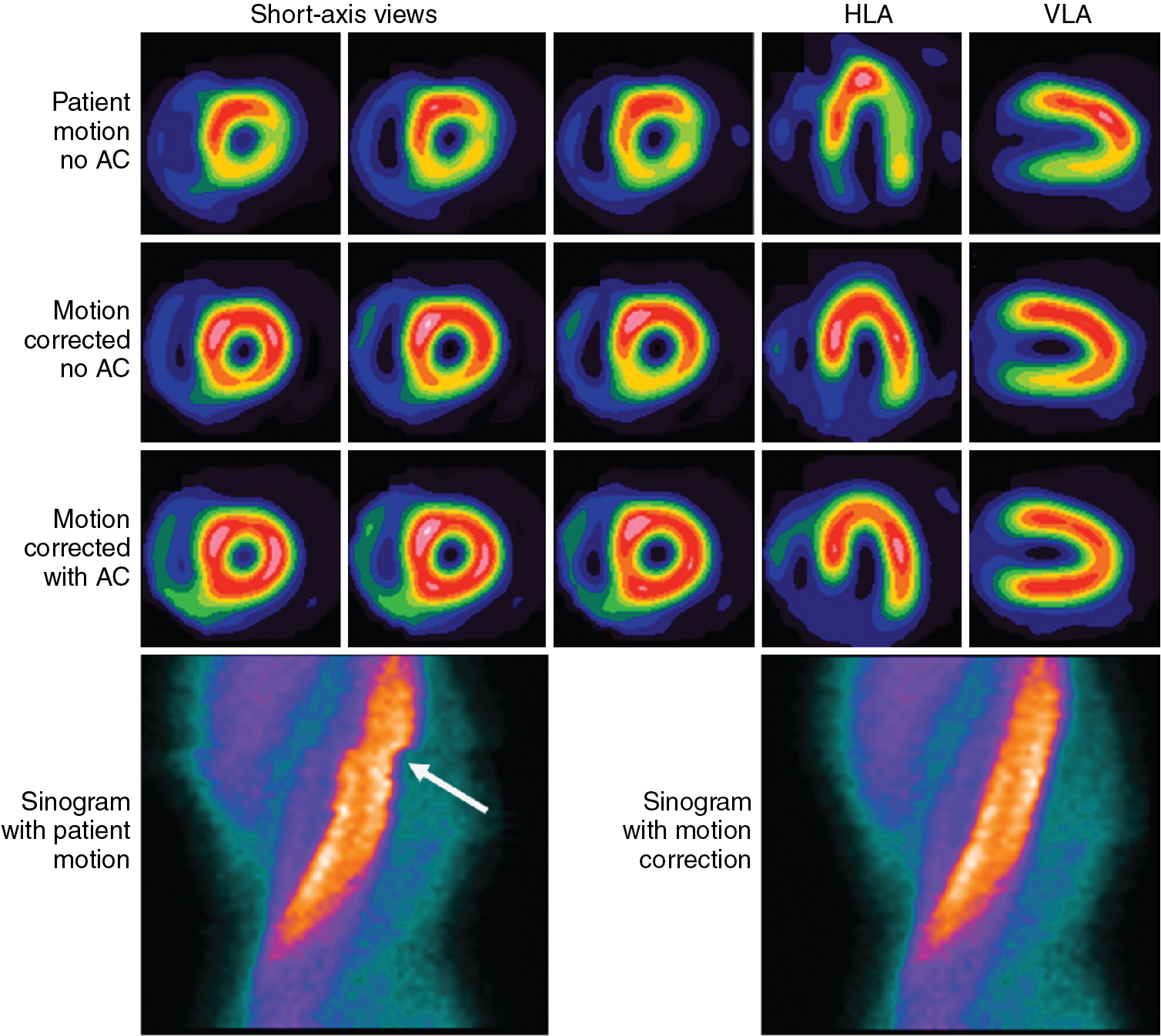
Patient movement, both voluntary and involuntary, can blur the image of the heart, decreasing spatial resolution and reducing the apparent uptake in the myocardium because of partial volume averaging. Nonrepetitive motion can lead to inconsistencies in the projection data and consequently introduce artifacts into the image. , Because the acquisition duration is several minutes, breath-hold approaches are not practical and the presence of patient motion is common. Axial motion of the heart can be detected by reviewing a movie loop of the acquired projection data. Detected motion can be manually corrected by shifting the projections to minimize motion. Abrupt patient motion in the transverse plane can be detected by looking for discontinuities in the sinogram of the projection data ( Fig. 1.4 ). Shifts can then be applied to approximately correct these breaks. Many cardiac analysis software packages provide tools to assist with these evaluations and corrections. Nevertheless, corrections, particularly of transverse motion, are often imperfect and care is always taken to minimize movement by keeping patients comfortable and stressing the need to remain still. Cardiac contraction and respiration are always present in the data set, but gating can be used to extract valuable information and reduce the loss of image quality caused by these motions. Gating is discussed in more detail later in this chapter.
Statistical noise in the projection data
Radioactive decay is a random process that is governed by Poisson statistics. Within a given time interval, the number of gamma rays detected by a gamma camera will fluctuate according to: σ 2 = N, where σ and N are the standard deviation and mean number of detected gamma rays, respectively. The relative noise, σ/N, is reduced by either increasing the amount of radioactivity injected into the patient or increasing the imaging time, both of which will increase the total number of detected gamma rays. The amount of radioactivity that can be injected, however, is limited by patient radiation exposure, and the acquisition duration is limited by the time available to image each patient each day and by patient comfort because long scan times can result in more patient movement. Noise in the projection data propagates into the image through the reconstruction process and so the effect of noise depends on the reconstruction algorithm used and the filtering applied.
Reconstruction
Algorithms
Filtered backprojection
Traditionally, the approach used for image reconstruction has been filtered backprojection (FBP). , A projection image shows the distribution of radioactivity in two dimensions and the collimator provides the direction that the gamma ray travels, but the distance of the radiation source from the collimator is unknown. The number of detected gamma rays (counts) in the projection are, therefore, spread uniformly across the FOV (backprojected) in front of the detector ( Fig. 1.5 ). This is done for all of the projections available. At the correct spatial locations of the activity distribution, the different backprojected rays intersect and build up the image. Because of the rotational acquisition of data, the data sampling is like spokes on a wheel: denser toward the hub and sparser toward the rim. This leads to a blurring in the image that falls off as the inverse of the distance from the source. To correct for this artifact, a ramp filter is applied to the projection data before backprojection (thus making it FBP).