Clinical cardiovascular magnetic resonance (CMR) had been in use for nearly 35 years and has become firmly established in the evaluation of congenital heart disease (CHD) in many ways, including anatomy, physiology, ventricular function, blood flow, and tissue characterization. In many instances, it is used as an adjunct to other imaging modalities such as noninvasive echocardiography and invasive angiography; however, in a number of areas such as vascular rings, blood flow, as well as ventricular volumes and mass, it has become the clinical “gold standard.” In addition, CMR offers several advantages over other imaging modalities, including lack of ionizing radiation, which is extremely important for infants and children who are more susceptible to DNA breakage leading to neoplastic disease and have more time to manifest cancer symptomatology than adults. Furthermore, with capabilities such as exquisite soft tissue contrast, a capacity for true three-dimensional (3D) imaging in many areas (e.g., anatomy, ventricular function, blood flow), accurate flow quantification, tissue characterization such as myocardial viability, T1 mapping for diffuse fibrosis and perfusion imaging, noninvasive labeling of the myocardium or blood (tagging), coronary imaging and freely selectable imaging planes without limitations to “windows” or overlapping structures make CMR the “one-stop-shop” for noninvasive imaging in children. There are also unique characteristics to CMR, such as building images over many heartbeats so that long-term function and flow are “built into the image” (instead of the imager having to do this mentally by visualizing hundreds of heartbeats), four-dimensional (4D) flow imaging or internal checks to flow (e.g., the flows in the branch pulmonary arteries must sum to the flow measured in the main pulmonary artery) that make hemodynamics especially accurate. These advantages, and continued advances in CMR hardware, software, and imaging techniques, are bringing CMR into even more widespread use in pediatric cardiology. With the advent of relatively new techniques—such as “real-time” cine and flow imaging, dark blood 3D sampling perfection with application-optimized contrasts using different flip angle evolution (SPACE) and fully navigator accepted coronary imaging—CMR is poised to become a first-line imaging modality in many situations in pediatric cardiology and CHD.
Although the application of CMR to CHD uses nearly all of the techniques discussed in the various chapters of this book, it nevertheless stands on its own as a separate discipline in the world of CMR. The multiple reasons for this can be divided into a few broad categories.
- 1.
Technical challenges: imaging infants and children is very demanding because they require both increased spatial resolution as a result of their small size as well as increased temporal resolution because of higher heart rates as compared with adults. CMR in adults makes many tradeoffs to make imaging quicker and simpler without sacrificing diagnostic accuracy, such as obtaining spatial resolution at the cost of temporal resolution and vice versa. Because many pulse sequences are made to image adult patients, the tradeoffs that can be performed in children can only be taken advantage of to a limited degree. In addition, children under 10 years of age usually need some form of sedation, which make sequences designed for breath-holding useless unless the child is paralyzed, intubated, and mechanically ventilated under anesthesia. Because the breath-holding technique is the mainstay of adult CMR, “work-arounds” have been developed to successfully image the pediatric patient. These modifications, or new approaches to CMR, must be understood for children to be imaged successfully.
- 2.
Anatomy of CHD: the anatomy of native CHD is very different from adult cardiology and demands a rigorous and systematic approach to make the correct diagnosis. In addition, because many CHDs rely on surgical as well as an increasing number of catheter-based therapies, the anatomic and physiologic information extracted from the CMR examination needs to keep these approaches in mind. As a corollary, the postoperative/interventional anatomy and hemodynamics in CHD must also be familiar to the physician performing the examination to assess for adequacy of the therapy and follow-up. For example, the connections between the major cardiac segments (atria, ventricles, and great vessels) along with venous anatomy can and are altered in many types of the diseases encountered in CHD (e.g., transposition of the great arteries [TGA]). Communications are present where they should not be (e.g., ventricular septal defects [VSD]), blood vessels from fetal life may still be present (e.g., patent ductus arteriosus), and some cardiac structures might not even be present or present in a markedly hypoplastic form (e.g., hypoplastic left heart syndrome). In the evaluation of CHD after surgery, conduits and baffles constructed to separate the circulations have little parallel in the adult world. As such, anatomy and morphology must be delineated by CMR in ways that are not required in adult heart disease and the physician interpreting the study needs to be schooled in the nuances of both the preoperative and postoperative anatomy of CHD.
- 3.
Physiology: the unique physiology of CHD is most often a result of the altered anatomy. Evaluation of shunts (e.g., VSD) plays a critical role in assessment of any disease entity in pediatrics and yet has a minor role in the adult world. CMR has recently become the only imaging modality to quantify aortic to pulmonary collateral flow development in single ventricles, again, a unique province of CHD. Determination of ventricular function in ventricles with strange and unusual shapes (single ventricles, L-looped ventricles) is routine in the practice of CMR in children and demands unique solutions. Assessment of the postoperative/interventional physiology where the surgeon, for example, creates a systemic to pulmonary artery shunt or creates an anastomosis between the cava and the pulmonary artery must be dealt with. CMR in CHD and in pediatrics must be adapted to fit these needs and the physician interpreting the study needs to understand the complex physiology.
Similar to other imaging modalities, CMR has limitations and challenges in the CHD population. Sedation, and in some instances, general anesthesia for infants and children to hold still for a 45- to 60-minute scan is always a consideration. Even if remaining motionless in the scanner is not an issue, cooperation by the preteen or teen may be problematic (e.g., breath-holding). In addition, intravascular coils, wires, stents, and clips may all cause artifacts if they are near the structure of interest and are found in a number of cases of CHD where catheter and surgical intervention has occurred. The lack of portability of CMR is disadvantageous, especially for the critically ill infant or child who would need to be moved to the CMR suite. And finally, patients with arrhythmias may not allow proper data acquisition; other patients may have bizarre T-waves or bundle branch blocks, which may not allow for proper triggering. This is becoming less of an issue now that “single shot” CMR, “real-time” CMR, and sequences with “arrhythmia rejection” are realities. Pacemakers are still a problem and remain a “relative contraindication”; though safety of MRI in adult patients with non-MRI conditional/legacy pacemakers and implanted cardioverter-defibrillators has been demonstrated, safety data specific to infants and children are currently lacking. Patients with them usually do not undergo CMR unless it is the only imaging modality that can obtain the data and change management (see Chapter 11 ).
This chapter discusses the present state-of-the-art of CMR in CHD and some of the newer techniques available. For simplicity, the imaging techniques discussed will be generic; however, some of the “lingo” of CMR will be related to the Siemen’s CMR scanners. The reader should understand that other manufacturers, for the most part, have similar sequences but under a different name.
Generalized Protocol of CMR for Congenital Heart Disease
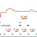
CMR for CHD is a technique that constantly requires fine tuning during an examination, in general, because unexpected findings turn up frequently, especially in pediatrics. Nevertheless, certain basic principles exist that can be formulated into a generalized protocol of CMR in CHD ( Fig. 12.1 ). The author does not claim this to be the only way to think about the process, but it is, in the author’s opinion, the most efficient and complete. It should be noted that the protocol needs to be individualized to the patient and the disease process.

In this section, each step of the protocol will demonstrate a different form of CHD, giving the reader a broad overview of the spectrum of lesions encountered.
Anatomic Imaging (Noncontrast)
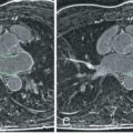
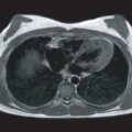
After localizers, anatomic data are acquired not only to survey the cardiovascular anatomy and make the “anatomic diagnosis” but also to act as localizers themselves for future physiologic and functional imaging. This is important in that physiologic and functional data must be interpreted in light of the prevailing anatomy. A full contiguous set of axial images from the diaphragm to the thoracic inlet is obtained (typically 40−50 images, Figs. 12.2 and 12.3 ); the author prefers “static” balanced steady-state free precession (bSSFP) images. This must be extended outside the thorax for special cases such as to the neck if arch anatomy is being evaluated (e.g., innominate artery branches in the neck) or if total anomalous pulmonary venous connections are suspected (e.g., connection below the diaphragm). Imaging that uses bSSFP depends on contrast between blood and the surrounding tissue, which is enhanced by using a high flip angle, and therefore the practice is to allow the scanner to select the highest flip angle possible. These axial images form the basis of examining the anatomy.


One disadvantage to using “static” bSSFP is that turbulence may present on the image as an absence of a structure (signal loss) as in the case of the pulmonary arteries in a single ventricle patient after a Blalock-Taussing shunt; typically, these are very difficult to visualize by this technique because the turbulence creates a major signal loss. This drawback can be compensated for by performing half-Fourier acquisition single-shot turbo spin echo (HASTE) imaging, which yields a set of dark blood images rapidly (or another type of dark blood imaging such as 3D SPACE, although HASTE is the quickest) and is performed while multiplanar reconstruction (MPR) is being done (see later). Alternatively, a set of axial cines can be performed to visualize these structures in the hope that a phase of the cardiac cycle will demonstrate the “missing” structure.
MPR, also called multiplanar reformatting, is a technique where a set of contiguous images (in this case, axial) are stacked atop each other and any plane can be reconstructed. This can be used after the axial stack above is obtained. The exact slice orientation and position can therefore be obtained for any future imaging during the study. In addition, the anatomy can be inspected from multiple views from just the set of axial images as a first pass. It can be used for any type of imaging. Finally, MPR can be used to demonstrate the salient point of the anatomy in instances where the scan needed to be terminated prematurely because of patient instability or technical issues after the stack of contiguous axial images had been obtained. “Curved cuts” can be used to delineate the important parts of the anatomy as well (see Fig. 12.3 ).
If needed, dark blood imaging can complement the bright blood imaging as in instances of vascular rings to visualize the trachea, coarctation of the aorta ( Fig. 12.4 ) or a systemic to pulmonary artery shunt. This type of imaging is used judiciously because it requires relatively long scanning times. A set of high-resolution double-inversion recovery dark blood images can be obtained or, if available, 3D SPACE, which can obtain a high-resolution slab in 5 minutes or less.

Function/Anatomy: Cine CMR ( Fig. 12.5 )
Either bSSFP or spoiled gradient recalled echo (GRE) sequences are used and are tailored to the lesion under study. Cine, along with phase contrast CMR (PCMR), are the major sequences used to delineate physiology and function (ventricular and valvar) in CMR of CHD. For example, to determine left ventricular (LV) volume overload in a patient with a VSD, a stack of LV short-axis images are acquired to measure LV volumes, mass, ejection fraction, stroke volume, and cardiac index; in the absence of valve regurgitation, the difference between LV and right ventricular (RV) stroke volumes is the added volume overload. If the LV volume overload was because of aortic regurgitation, a cine of the LV outflow tract in multiple views will be added to the short-axis stack to visualize the regurgitant jet.

Cine imaging is also used to delineate the anatomy as stated in the previous section ( Fig. 12.6 ). If coarctation of the aorta is present, turbulence should be noted on cine imaging unless there are multiple collaterals, the coarctation is not severe, or there is poor LV function. Caution must be used, however, when using this signal void to assess the degree of stenosis (or regurgitation if imaging valves) because it must be viewed in light of CMR physics similar to echocardiography (e.g., frame rate, angle of incidence). The size of the signal void is a function of a number of factors such as the echo time (TE, where longer TEs increase the signal void size and shorter TEs decrease it). In addition, the size of the signal void is also a function of the direction of the stenotic jet relative to the orientation of the image voxel. Finally, bSSFP imaging may underestimate the signal void seen on GRE sequences.

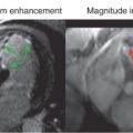
Cine is also used to visualize the anatomy of valves, typically en face, and is obtained many times during PCMR ( Fig. 12.7 ; also see Fig. 12.9 ). For example, to visualize a bicuspid aortic valve, the most common CHD, an en face view of the valve is performed by lining up the imaging plane perpendicular to the LV outflow tract in two orthogonal views at the level of the aortic valve. This typically results in the equivalent of a “parasternal short-axis view” by echocardiography. Either bSSFP or GRE with a high flip angle (e.g., 25 degrees) can be used, although the author prefers GRE because the high signal of the blood flowing into the imaging plane outlines the valve leaflets and gives exceptionally fine detail of the valve (as obtained in the magnitude images of PCMR). Examples of a trileaflet, bicuspid, and unicuspid aortic valve are in Figs. 12.7 and 12.8 .


Anatomy: Gadolinium-Based CMR ( Figs. 12.9–12.11 )
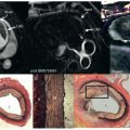
The two types of 3D gadolinium techniques for anatomy (both static [see Figs. 12.10 and 12.11 ] and time-resolved or “dynamic” [see Figs. 12.9 and 12.10 ] versions) are then performed as a complementary imaging tool because they not only add a special type of 3D dataset, which can be rotated and manipulated in many different ways, but also can be used to image smaller vessels much better than other techniques. This may also be used to create a shaded surface display, a volume-rendered 3D image (see Figs. 12.10 and 12.11 ) or a standard tessellation language (STL) file to be used to build a 3D printed model. A recent development has been an inversion recovery gradient echo (IR-GRE) technique used in conjunction with either gadofosveset trisodium or other gadolinium agents in a “slow drip” injection, which is both electrocardiogram (ECG) based and navigator based; this technique allows for submillimeter resolution and has been extremely useful in infants and children, especially for small vessels such as the coronary arteries (see Coronary subsection).


Blood Flow: Phase Contrast CMR ( Figs. 12.7, 12.8, and 12.12 )
After gadolinium imaging, blood flow data are obtained and, similar to cine CMR, are tailored to the lesion under study By performing PCMR after gadolinium injection, increased signal-to-noise ratio (SNR) is obtained in the PCMR sequences (as well as not allowing the scanner to remain idle waiting for 10 minutes to pass for viability imaging—see later). “Through plane retrospectively gated” images are acquired so that flow can be measured across the entire cardiac cycle whereas in-plane velocity mapping can be used for measuring peak velocities and visualizing flow directionality. PCMR is extremely useful in CHD for understanding hemodynamics and physiology and is used for most cases. For example, in the patient described previously with a VSD, through-plane PCMR is obtained across the aortic and pulmonary valves to measure the pulmonary to systemic flow ratio (Qp/Qs), which has been validated against oximetry. As an internal check (one of the strengths of the accuracy of PCMR), flow in the branch pulmonary arteries (should equal flow through the main pulmonary artery) and in the cavae (should equal flow in the aorta in the absence of aortic to pulmonary collaterals) are obtained. As another internal check, LV output, as calculated using cine CMR (in the absence of mitral regurgitation), should equal the forward flow as measured across the aorta using through-plane PCMR, and the same is true of RV output.

PCMR, in conjunction with cine CMR, can calculate other important parameters of function such as valve regurgitation (see Fig. 12.12 ). For example, patients who have undergone complete common atrioventricular canal repair can sometimes manifest left atrioventricular valve regurgitation as a sequela. To assess this quantitatively, the difference in the LV stroke volume and the forward flow through the aorta would be the left atrioventricular valve regurgitant volume in the absence of a VSD. This volume divided by the stroke volume (multiplied by 100) is the left atrioventricular valve regurgitant fraction. Forward flow across the left atrioventricular valve by using PCMR across it should equal LV stroke volume (in the absence of any other residual shunts or aortic insufficiency) and may be used as an internal check; however, it may be difficult at times to line this imaging plane exactly perpendicular to flow.
As mentioned, PCMR can also be used to assess valve anatomy (see Figs. 12.7 and 12.8 ). Through-plane PCMR can outline the leaflets of valves when imaged en face (both on the phase and the magnitude images) and can be successful when routine cine imaging is not.
Finally, 4D flow imaging is becoming more commonplace in CHD, and techniques and tools used are continually being developed. A full treatment of 4D flow in CHD is beyond the scope of this chapter; however, one image of 4D flow of a coarctation of the aorta is shown in Fig. 12.8 .
Tissue Characterization ( Figs. 12.13 and 12.14 )
There are a number of different techniques used in CHD that are helpful to characterize myocardial tissue.


Related posts:
 Use of Navigator Echoes in Cardiovascular Magnetic Resonance and Factors Affecting Their Implementation
 Acute Myocardial Infarction: Cardiovascular Magnetic Resonance Detection and Characterization
 Atherosclerotic Plaque Imaging: Coronaries
 Cardiac Iron Loading and Myocardial T2*
 Pulmonary Vein and Left Atrial Imaging
 Noncardiac Pathology
Stay updated, free articles. Join our Telegram channel

Full access? Get Clinical Tree


