Cervical Spine Emergencies
- Mark Bernstein
- Alexander B. Baxter
- F.A. Mann
- Alexander B. Baxter
Each year in North America approximately 3 million patients are evaluated for spinal injury. Although the incidence of vertebral fracture and spinal cord injuries is low, the consequences of a missed injury or delayed diagnosis can be devastating. Although most cervical spine fractures are localized to a single vertebra, two or three noncontiguous injuries are often seen in high-energy trauma, occurring in up to 25% of patients.
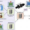
Accurate diagnosis requires cooperation between clinician and radiologist, a reliable and repeatable approach to interpreting cervical spine computed tomography (CT), and the awareness that a patient may have a significant and unstable ligamentous injury despite normal imaging findings. This chapter reviews imaging modalities, approach to image evaluation, concepts of stability, and descriptions of common cervical spine injury patterns.
Imaging Approach and Modalities
Screening
Emergency physicians triage patients with suspected cervical spine injury into high- and low-risk groups, those who require imaging for confirmation and accurate evaluation and those who can be confidently discharged. Both the Canadian C-spine (Cervical Spine) Rule (CCR) and the National Emergency X-radiography Utilization Study (NEXUS) criteria provide guidelines for deciding which patient for whom imaging is not indicated ( Table 6-1 ). Anyone with midline tenderness, focal neurologic deficit, altered sensorium, or a distracting injury requires CT imaging, as well as protection of the spine in a hard cervical collar. Other high-risk factors include age greater than 65 years and significant energy-transfer mechanism. Systematic use of validated clinical decision rules substantially reduces unnecessary cervical spine imaging in adult (CCR, NEXUS) and pediatric (NEXUS) victims of blunt trauma.
| Canadian C-Spine Rule (CCR) Imaging Not Indicated | NEXUS Criteria (Low Risk) Imaging Not Indicated |
|---|---|
Absence of high-risk factors, including:
| No midline cervical tenderness No focal neurologic deficits No intoxication or indication of brain injury No painful distracting ‡ injuries Normal alertness |
∗ ”Dangerous mechanism” defined as fall from an elevation of 3 feet or five stairs, axial load to the head (e.g., diving), motor vehicle collision at high speed (>45 mph or >100 km/hr) or with rollover or ejection, collision involving a motorized recreational vehicle (e.g., all-terrain vehicle), or bicycle collision (M. Copass, personal communication, 2005).
† Simple rear-end motor vehicle collision excludes being pushed into oncoming traffic, being hit by a bus or a large truck, a rollover, and being hit by a high-speed vehicle (M. Copass, personal communication, 2005).
‡ ”Distracting” injuries identified by loss of two-point discrimination ≥ 4 mm (M. Copass, personal communication, 2005).
Because osseous displacement that occurs at the moment of impact can be subsequently reduced by recoil and muscle spasm, and because placement of a hard collar can mask instability by maintaining vertebral alignment, an apparently normal examination should be viewed with skepticism in any patient with neurologic deficit or persistent pain; significant ligamentous injury may be present despite normal CT findings. Magnetic resonance imaging (MRI) detects ligamentous edema with great sensitivity, but ligamentous edema alone does not necessarily indicate an unstable injury. Dynamic evaluation with delayed flexion and extension radiographs under neurosurgical supervision is the sine qua non for identification of unstable ligamentous injury, and patients with pain but without neurologic symptoms are generally discharged in a hard cervical collar. Flexion/extension radiographs are best performed 1 to 2 weeks after injury, after muscle spasm has had sufficient time to resolve.
Conventional Radiographs
Conventional radiographs of the cervical spine have been replaced by multidetector CT as the primary screening tool for detection and characterization of cervical spine trauma. In the initial imaging evaluation of cervical spine injury, the American College of Radiology (ACR) Appropriateness Criteria recommends conventional radiography only when CT is not available.
Computed Tomography
Multidetector CT with thin-section reconstruction and sagittal and coronal multiplanar reformations (MPRs) identifies the exact location and displacement of fractures and bone fragments and defines the extent of any potential spinal canal, neuroforaminal, or vascular compromise.
Computed Tomography Angiography
The aim of CT angiography (CTA) in the setting of acute cervical spine trauma is to detect asymptomatic vascular injury and prevent subsequent stroke with early anticoagulation. Vascular injury is present in greater than 20% of patients who are screened using the following criteria:
Diffuse axonal injury with Glasgow Coma Scale score of less than 6.
Skull base fracture extending to the carotid canal.
Le Fort II or III fracture.
Severe cervical spine fractures.
Cervical spine fractures involving a transverse foramen.
Approximately 20% of untreated patients in whom an asymptomatic cerebrovascular injury is detected will suffer a significant complication, usually embolic infarct or intracerebral hemorrhage. Less than 1% of medically treated patients will do so.
Magnetic Resonance Imaging
When available and following CT assessment of osseous spinal integrity, MRI is valuable in evaluation of patients with an acute neurologic deficit because it accurately identifies epidural hematoma, traumatic disk herniation, and spinal cord contusion. But the immediate clinical question in acute spine trauma is always “Does the patient require surgical decompression?” and evaluation of canal and neuroforaminal patency is adequately accomplished by CT alone.
Sagittal T2 and gradient-echo magnetic resonance (MR) sequences are of particular value in depicting patterns predictive of neurologic outcome: normal, single versus multilevel edema, spinal cord hemorrhage, and cord rupture.
Image Evaluation and Interpretation
An accurate clinical history that specifies injury mechanism and location of pain is essential for interpreting the significance of subtle findings, particularly in older patients with degenerative disk disease or prior injury. To avoid the common errors of observation failure and satisfaction of search, it is helpful to have a checklist in mind that ensures all important structures are examined and that common injury patterns are sought as outlined in the following subsections.
Transaxial Images
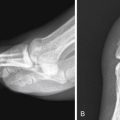
Examine the integrity and rotational alignment of each vertebral segment, facet joint articulations, cervical soft tissues, spinal canal diameter, and neuroforaminal patency ( Fig. 6-1 , A and B ).

Midline Sagittal Images
Evaluate the prevertebral soft tissues, the thickness of which should be less than 5 mm at C2 or 15 mm at C5 (due to the normal esophagus). The anterior spinal line, posterior spinal line, and spinolaminar line should be continuous, and interspinous distances should be uniform. The dens-basion distance should be 9.5 mm or less, and a line drawn vertically along the dorsal body of C2 (posterior axial line) should be less than 5.5 mm posterior to the basion. The atlantodental interval should be less than 3 mm in adults. The C1-2 interspinous distance measured at the spinolaminal line should be less then 7.8 mm (see Fig. 6-1 , C ).
Parasagittal Images
The occipital condyles should be intact. The atlantooccipital and atlantoaxial articulations should be congruent, and the facets should align normally, with the inferior articulating facet of the upper vertebral body posterior to the superior articulating facet of the adjacent lower vertebral body (see Fig. 6-1 , D ).
Coronal Images
The occipital condyles, C1, and C2 should be intact and aligned. The dens should be centered between the lateral masses of C1 (see Fig.6-1 , E ).
In addition to developing a repeatable approach, maintaining suspicion that a radiographically normal spine may still be injured, and appreciating the surgical decisions that must be made in the acute setting, familiarity with the appearance of common cervical spine fracture patterns and an understanding of spinal stability is invaluable.
Concepts of Stability
A stable spine is able to withstand physiologic loads without producing mechanical deformity, progressive neurologic injury, or worsening pain. These are biomechanical rather than anatomic concepts, and imaging studies predict stability only indirectly, by evaluating the condition of the vertebrae and their ligamentous supports. Stability at the craniocervical junction depends on the integrity of the transverse ligament, the tectorial membrane, and the alar and apical ligaments and their bony attachments.
Both clinically and radiologically, the three-column concept of Denis is most widely applied for evaluating thoracolumbar spine stability ( Fig. 6-2 ). It is reasonable to extrapolate these concepts to the subaxial (C3-C7) cervical spine. In Denis’s model the anterior column includes the anterior longitudinal ligament and the anterior vertebral body and disk. The middle column includes the posterior vertebral body cortex, posterior disk anulus, and the posterior longitudinal ligament. The posterior column includes the posterior bony arch, facets, and the posterior ligament complex (PLC) composed of the ligamentum flavum, the facet joint capsules, and the interspinous and supraspinous ligaments. Injury of two or three columns is considered unstable, with the key contributing factor being disruption of the middle column.

Injury Patterns—Craniocervical Spine
Atlantooccipital Dissociation
Atlantooccipital dissociation (AOD) results from high-energy trauma sufficient to separate the skull base from the upper cervical spine. It is invariably accompanied by severe neurologic dysfunction and concomitant injuries to the torso and extremities. The spectrum of AOD ranges from true dislocation, which is usually lethal, to subluxation, which is unstable but survivable. Most injuries in AOD are limited to soft tissue trauma (alar ligaments and tectorial membrane). Fractures are uncommon and when present are usually bilateral occipital condyle and clival avulsion fractures. Mixed bony and ligamentous injury patterns consist of bilateral occipital condyle fractures with associated tectorial membrane disruption.
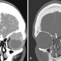
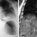
Cross-sectional imaging, particularly CT, is most accurate in detecting AOD in the acute setting. Abnormal findings in AOD include prevertebral soft tissue swelling at C2, a basion-dens interval greater than 9.5 mm measured in the midsagittal plane, and atlantooccipital condyle articulations greater than 1.4 mm in width ( Fig. 6-3 , A and B ). Associated vascular injury can be evaluated with CTA, MR angiography, or catheter angiography.

Occipital Condyle Fractures
Several classification schemes for occipital condyle fractures have been proposed. However, in the absence of findings for AOD, description rather than classification of occipital condyle fractures seems warranted because no outcome differences by subtype have been demonstrated.
Atlantoaxial Rotatory Fixation
Atlantoaxial rotatory fixation (AARF) is a form of atlantoaxial dissociation characterized by rotational malalignment between the C1 and C2 vertebrae. AARF occurs within the physiologic range of motion at the C1/C2 joints and is thought to be secondary to muscle spasm and swelling or tearing of joint capsular soft tissues. In adults, AARF is invariably traumatic in cause and is associated with cervical pain and torticollis.
AARF is most commonly a pure rotational injury, with the odontoid as the pivot. In type I injuries, intact transverse and alar ligaments prevent excessive anterior displacement. In type II injuries, isolated disruption of the transverse ligament produces 3 to 5 mm anterior translation with rotation centered on one of the articular masses. Type III injuries have more than 5 mm translation with rotation because of a combination of transverse ligament and alar ligament disruption. Posterior displacement of C1 on C2 secondary to alar and transverse ligament injury combined with a deficient odontoid characterizes type IV injuries.
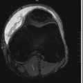
Computed tomography shows rotation or dislocation at the C1-C2 lateral masses, where the jaw and the neck appear pointed in different directions ( Fig. 6-4 , A and B ). True fixation versus simple head turning can be confirmed clinically or by repeating CT with patient in maximal rotation to the opposite direction, though this is rarely necessary. Potential rotational injury to the stretched contralateral vertebral artery is best evaluated with CTA (see Fig. 6-4 , C ). Early diagnosis leads to improved outcome.

C1—Jefferson and Variant Jefferson Fractures
The first cervical vertebra (C1, atlas) supports the cranium through its articulations with the occipital condyles. Anatomically it is a simple bony ring with two lateral masses connected anteriorly and posteriorly by the neural arches. This unique shape allows for great range of motion. The odontoid process of C2 (axis) articulates with the anterior arch of C1 and is held in place by the transverse ligament, the integrity of which is the key determinant of atlantoaxial stability. Transverse ligament disruptions are most commonly avulsions that heal with nonoperative management; however, a few purely ligamentous failures will remain truly unstable.
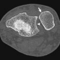
The classic Jefferson fracture results from axial loading on a straight cervical spine with forces transmitted from the vertex through the occipital condyles to the C1 lateral masses ( Fig. 6-5 , A ). The result is a four-part fracture. Fractures occur at the weakest points of the ring, the anterior and posterior junctions of the arches and lateral masses (see Fig. 6-5 , B ). In the classic Jefferson fracture, the transverse ligament remains intact and there is no subluxation between C1 and C2. Thus, in the absence of concomitant fractures or ligamentous disruption, the classic Jefferson burst is both mechanically and neurologically stable.

Asymmetric axial loading produces the atypical Jefferson fracture, with two or three rather than four fractures of the C1 ring. In this fracture the transverse ligament is disrupted, and C1 fragments are laterally subluxed relative to C2 (see Fig. 6-5 , C ). Transverse separation of fracture fragments, greater than 5.4 mm on CT or 7 mm on radiographs (odontoid view), indicates transverse ligament injury and instability. This measurement, known as the rule of Spence , can be made on transverse or coronal CT. Other signs of instability include avulsion of the C1 tubercle (transverse ligament insertion), two anterior ring fractures with an intact posterior arch, and an atlantodental interval greater than 3 mm in adults or 5 mm in children. Magnetic resonance imaging is highly sensitive in directly identifying transverse ligament discontinuity. Pitfalls in the evaluation of C1 fractures include congenital fusion anomalies and aplasias that may simulate fractures. These are identified by their smooth, well-corticated margins.
C2—Odontoid Fractures
C2 (axis) fractures represent approximately 15% to 20% of all cervical spine fractures, and the majority of these involve the odontoid process. Odontoid fractures are especially common in older adults and may occur following even minor trauma. In patients younger than 50 years, odontoid fractures often result from high-energy events and are commonly associated with other fractures and subluxations, frequently unstable in the aggregate.
A type I fracture is a small apical avulsion at the alar or apical ligament insertion ( Fig. 6-6 , A ). Type II, the most common C2 fracture, is a simple transverse odontoid fracture (see Fig. 6-6 , B ). Type III fractures extend variably into the C2 body (see Fig. 6-6 , C ). In the absence of other indications of craniocervical instability (increased dens-basion distance, incongruous articular surfaces), type I fractures are considered stable. Type II fractures that show 4 mm or greater displacement or are comminuted have a high incidence of nonunion. Patients in this group are also more likely to have an associated neurologic injury or respiratory compromise. Type III odontoid fractures almost always heal with rigid collar immobilization.

C2—”Hanged-Man” Fractures
The hanged-man fracture, or traumatic C2 spondylolisthesis, classically results from hyperextension with fracture of both of the pars interarticularis or pedicles of C2 ( Fig. 6-7 , A ). Although the eponym hanged-man fracture is derived from historic cases of judicial hanging, today most result from falls and motor vehicle crashes. They are often asymmetric and are considered atypical if the fracture propagates into the posterior vertebral body. Atypical fracture patterns are actually quite common and may involve the transverse foramen, placing the vertebral artery at risk for injury (see Fig. 6-7 , B ). The classification system devised by Effendi and modified by Levine and Edwards is the most widely used.
Type I fracture: Bilateral pars fractures without significant translation or angulation. These result from hyperextension or axial loading and are considered mechanically and neurologically stable.
Type II fractures : C2-3 disk disruption with anterior translation of the C2 body. These are the most common type of hanged-man fracture and result from hyperextension and axial loading with subsequent hyperflexion. Type II fractures are unstable.
Type IIA fractures : Unstable flexion-distraction injury resulting in C2 body angulation without translation.
Type III fractures : Anterior translation and angulation with facet subluxation or frank dislocation. These are highly unstable injuries that result from hyperflexion and compression.