, and the primary unknowns are the extracellular potential  and the transmembrane potential
  . Hence, the intracellular potential reads
  . For all
 with
 such that, for all
  with
with  ,
,
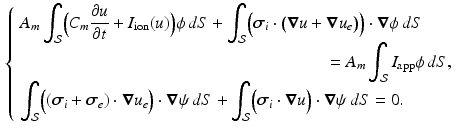
(1)
 denotes the ratio of membrane area per unit volume,
  is the membrane capacitance per unit surface,
  a reaction term representing the ionic current across the membrane and also depending on local ionic variables satisfying additional ODEs – in our case we use the ionic model of [8] – and
  a given prescribed stimulus current, when applicable. We define the intra- and extra-cellular diffusion tensors
  and
and  by
by![$$\begin{aligned} {\varvec{\sigma }}_{i, e} = \sigma _{i,e}^t {\varvec{I}} + (\sigma _{i,e}^l - \sigma _{i,e}^t) \bigl [ I_0(\theta ) \varvec{\tau }_0 \otimes \varvec{\tau }_0 + J_0(\theta ) \varvec{\tau }_0^\perp \otimes \varvec{\tau }_0^\perp \bigr ], \end{aligned}$$](/wp-content/uploads/2016/09/A339585_1_En_46_Chapter_Equ2.gif)
(2)
 denotes the identity tensor in the tangential plane – also sometimes called the surface metric tensor –
  is a unit vector associated with the local fiber direction on the atria midsurface, and
  such that
  gives an orthonormal basis of the tangential plane. The functions
 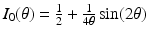 and
and 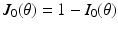 represent the effect of an angular variation
  of the fiber direction across the wall. A typical physiological simulation of the model is presented in Fig. 1 in a healthy case, with the parameters given in Table 1. For details on the modeling formulation and parameter calibration we refer to [4, 7], and also to [16] where this model was used in the atria for numerical simulations of complete realistic electrocardiograms.
Table 1.
Conductivity parameters (all in  ) and maximal conductance
  in the different atrial areas (all in
  ) with RT = regular tissue, PM = pectinate muscles, CT = crista terminalis, BB = Bachman’s bundle, FO = fossa ovalis
) and maximal conductance in the different atrial areas (all in ) with RT = regular tissue, PM = pectinate muscles, CT = crista terminalis, BB = Bachman’s bundle, FO = fossa ovalis |  |  |  |  (RT) (RT) |  (PM) (PM) |  (CT) (CT) |  (BB) (BB) |  (FO) (FO) |
|---|---|---|---|---|---|---|---|---|
 |  |  |  | 7.8 | 11.7 | 31.2 | 46.8 | 3.9 |

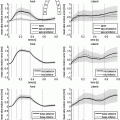
Fig. 1.
Atrial electrical depolarization and corresponding synthetic front data
2.2 Data of Interest
We assume in this work that the patient-specific depolarization front is measured, as is the case when isochrones are available. From a mathematical standpoint, the measurement procedure can be modeled by considering that, for a particular solution of (1) denoted by  and associated with patient-specific parameters and initial conditions, we have at our disposal the time evolution of the front
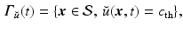
defining  as a threshold value characterizing the front, and the already traveled-through region is given by
![$$\begin{aligned} \mathcal S^{\text {in}}_{\breve{u}}(t) = \{\varvec{x} \in \mathcal S, \, \breve{u}(\varvec{x},t) > c_{\text {th}}\}, \end{aligned}$$” src=”/wp-content/uploads/2016/09/A339585_1_En_46_Chapter_Equ4.gif”></DIV></DIV><br />
<DIV class=EquationNumber>(4)</DIV></DIV>up to some measurement noise. These data can be represented as a sequence of images – denoted by <SPAN id=IEq41 class=InlineEquation><IMG alt=$$z(t)$$ src=]() – that essentially take two different values inside and outside the traveled-through region. Our objective is to use the image sequence
– that essentially take two different values inside and outside the traveled-through region. Our objective is to use the image sequence  to reconstruct the target solution
  , in a context where the initial conditions and some physical parameters are uncertain.
Get Clinical Tree app for offline access

and associated with patient-specific parameters and initial conditions, we have at our disposal the time evolution of the front(3)
as a threshold value characterizing the front, and the already traveled-through region is given by to reconstruct the target solution , in a context where the initial conditions and some physical parameters are uncertain.3 Estimation Methodology
3.1 Sequential Estimation Principles
We consider a general dynamical system  , where y is the state variable, A the model operator, and
  some parameters of interest. In this abstract setting, we consider a specific target trajectory
  , where
  is a known a priori whereas
  is unknown, and assuming the same type of decomposition for the parameters
  . We further assume that we have at our disposal some indirect measurements of the target trajectory represented by the observation variable z(t). Our estimation problem consists in reconstructing the solution
  from the data z(t).
, where y is the state variable, A the model operator, and some parameters of interest. In this abstract setting, we consider a specific target trajectory , where is a known a priori whereas is unknown, and assuming the same type of decomposition for the parameters . We further assume that we have at our disposal some indirect measurements of the target trajectory represented by the observation variable z(t). Our estimation problem consists in reconstructing the solution from the data z(t).As a prerequisite to any estimation strategy, we must be able to define – at each time – a similarity/discrepancy measure  between the data z and the state variable y. When
  vanishes, the state is exactly compatible with the data. By contrast, when
  is non-zero, the data indicate that
  .
.
between the data z and the state variable y. When vanishes, the state is exactly compatible with the data. By contrast, when is non-zero, the data indicate that .To achieve our estimation objective, we adopt a so-called sequential strategy where we define an observer system – also known as sequential estimator system – as a new dynamical system of the form
 Motion Estimation Using Ultrafast Ultrasound Imaging Tested in a Finite Element Model of Cardiac Mechanics
 Recognition in Cardiac CT Images
 Anisotropic Myocardial Stiffness from Magnetic Resonance Elastography: A Simulation Study
 Feature Learning for Myocardial Segmentation of CP-BOLD MRI
 Biomechanical Modeling of Cardiac Amyloidosis – A Case Study
 Edge Map (PEM) for 3D Ultrasound Image Registration and Multi-atlas Left Ventricle Segmentation


Related posts:
Motion Estimation Using Ultrafast Ultrasound Imaging Tested in a Finite Element Model of Cardiac Mechanics
Anisotropic Myocardial Stiffness from Magnetic Resonance Elastography: A Simulation Study
Biomechanical Modeling of Cardiac Amyloidosis – A Case Study
Stay updated, free articles. Join our Telegram channel
Full access? Get Clinical Tree