Fig. 2.1
DSCT with two independent measurement systems. (a) First generation. The system angle between both measurement systems is 90°. (b) Second generation. To increase the SFOV of detector B, a larger system angle of 95° was chosen. With the third generation DSCT, the SFOV of detector B was further increased to 35.5 cm
Meanwhile, three generations of DSCT systems have been commercially introduced. The first DSCT, the SOMATOM Definition (Siemens Healthcare, Forchheim, Germany) was introduced in 2006 [1]. The two measurement systems are mounted onto the rotating gantry with an angular offset of 90°. Detector A covers the full scan field of view (SFOV) of 50 cm diameter, while detector B covers a smaller 26 cm SFOV as a consequence of space limitations on the gantry. Both detectors simultaneously acquire 64 overlapping 0.6 mm slices by means of a z-flying focal spot technique [2]. The gantry rotation time is 0.33 s. The second DSCT, the SOMATOM Definition Flash (Siemens Healthcare, Forchheim, Germany) was introduced in 2009. The angular offset of both measurement systems was increased to 95° to provide a larger SFOV of 33 cm for the B-detector. Both detectors simultaneously acquire 128 overlapping 0.6 mm slices at a fastest gantry rotation of 0.28 s. The third DSCT, the SOMATOM Force (Siemens Healthcare, Forchheim, Germany) was made available in 2014. It provides a further increased SFOV of 35.5 cm of the B-detector and simultaneous acquisition of 196 overlapping 0.6 mm slices per detector at a fastest gantry rotation of 0.25 s.
DSCT systems provide significantly improved temporal resolution for cardio-thoracic and cardio-vascular imaging. The shortest data acquisition time for an image corresponds to a quarter of the gantry rotation time. In parallel geometry, 180° of scan data (a half-scan sinogram) are sufficient for image reconstruction. Due to the 90° angle between both x-ray tubes, the half-scan sinogram can be split into two 90° data segments which are simultaneously acquired by the two measurement systems at the same anatomical level. For the first generation DSCT with trot = 0.33 s the temporal resolution is trot/4 = 83 ms. For the second generation DSCT with trot = 0.28 s it is 75 ms, slightly more than a quarter of the gantry rotation time because of the increased angle between both measurement systems (95°). With the third generation DSCT with trot = 0.25 s a temporal resolution of 66 ms is achieved. Note that this temporal resolution is independent of the heart rate of the patient – multi-segment reconstruction approaches used in single source CT to improve temporal resolution depend on both the heart rate and the rotation time of the respective CT scanner and require regular heart rates with little variation for optimum performance. Meanwhile, several clinical studies have demonstrated the potential of DSCT to reliably perform coronary CT angiographic studies also in patients with high and irregular heart rates [3–5].
With a DSCT system, dual energy (DE) data are acquired by simultaneously operating both x-ray tubes at different x-ray tube voltages (kV-settings), e.g. 80 kV and 140 kV. The scan parameters can be individually adjusted for both measurement systems, resulting in a flexible choice of scan protocols with no restrictions in spiral pitch or available tube current (mA) per x-ray tube. In combination with on-line anatomical tube current modulation (CAREDose 4D, Siemens Healthcare, Forchheim, Germany), the radiation dose to the patient can be fine-tuned to patient size and the planned examination.
The quality of DE CT examinations relies on the effective separation of the energy spectra. More spectral overlap and worse energy separation mean less efficient and less precise tissue differentiation, which has to be compensated by increased radiation dose. DSCT systems have the potential to optimize spectral separation by introducing additional pre-filtration into the high-kV beam, e.g. by means of a filter that can be moved into the beam when needed and moved out for non-DE applications.
The SOMATOM Definition Flash uses an additional tin filter (Sn) with a thickness of 0.4 mm to shift the mean energy of the 140 kV spectrum from 69 to 89 keV, see Fig. 2.2. The mean energy of the 80 kV spectrum is 52 keV. The tin filter has several benefits. It increases the spectral separation between the low- and the high-energy spectrum, it narrows the high-energy spectrum (which results in better dose efficiency and less beam hardening artifacts), and it reduces cross-scattering. Primak et al. [6] found that adding tin filtration to the high-kV tube improved the DE contrast between iodine and calcium as much as 290 %. The voltage combination 80 kV/140 Sn kV is available for DE scanning at maximum spectral separation. The additional 100 kV/140 Sn kV scan option provides increased power reserves for big patients.
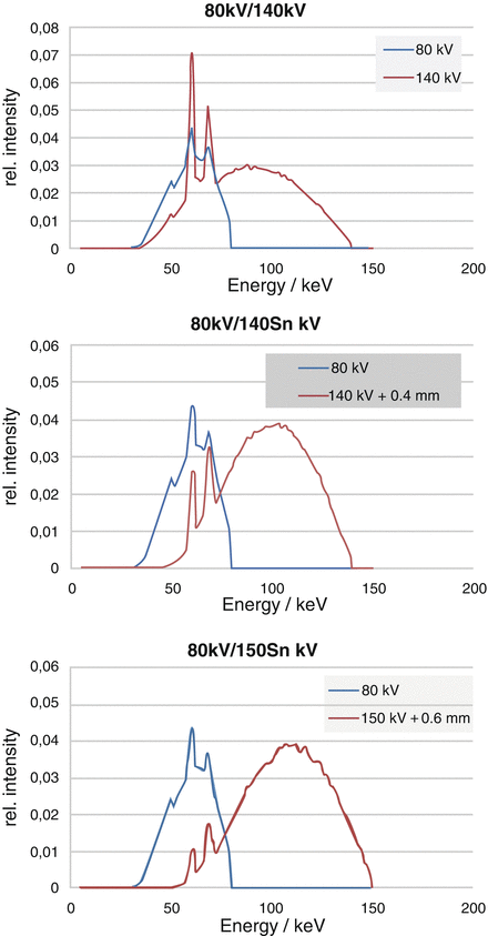

Fig. 2.2
Top: Standard 80 kV and 140 kV spectra. The mean energy of the 140 kV spectrum is 69 keV. The mean energy of the 80 kV spectrum is 52 keV. Both spectra overlap significantly. Center: 80 kV spectrum and 140 kV spectrum with additional 0.4 mm tin pre-filtration. Note the shift of the 140 kV spectrum to higher energies. The mean energy is now 89 keV. Bottom: 80 kV spectrum and 150 kV spectrum with additional 0.6 mm tin pre-filtration. Note the further reduced spectral overlap
The SOMATOM Force further improves spectral separation by providing 150 kV x-ray tube voltage with more aggressive tin pre-filtration (0.6 mm) to acquire the high-energy CT data (see Fig. 2.2). Seventy kilovolts, 80 kV and 90 kV x-ray tube voltage are available to acquire the low-energy CT data, with sufficient power reserves to scan adults and larger patients as a result of the high tube current (mA) reserves of the new VECTRON x-ray tube (Siemens Healthcare, Forchheim, Germany) at low kV (up to 1,300 mA at 70 kV, 80 kV and 90 kV).
One method to quantify the performance of a DE CT acquisition technique with regard to energy separation and material differentiation capability is the use of DE ratios. The DE ratio of a material is defined as its CT-number (in Hounsfield units HU) at low kV divided by its CT-number (in HU) at high kV. Soft tissue, as an example, has a DE ratio close to 1, fat has a DE ratio <1, bone and iodine have DE ratios >1. As a representative example, we focus on the DE ratio of iodine. A frequently used application relies on the acquisition of DE CT data with administration of iodinated contrast agent. The spectral information is then used to compute both an iodine image, which visualizes the iodine uptake in different tissues, and a virtual non-enhanced image with the iodine removed, which corresponds to a true non-enhanced CT image without administration of contrast agent. This application has e.g. been used to characterize renal masses as benign or malignant [7], or to visualize perfusion defects in the lung parenchyma [8] or in the myocardium [9] The DE iodine ratio is approximately independent of mAs and reconstruction parameters, and depends only weakly on the iodine concentration for reasonably low amounts of iodine. The image noise in virtual non-enhanced images mainly depends on the DE iodine ratio and decreases with increasing DE iodine ratio. The higher the DE iodine ratio, the better is the quality of the virtual non-enhanced images and the corresponding iodine images, and the more precisely can iodine be differentiated and quantified.
The DE iodine ratios for different DE CT acquisition techniques are shown in Fig. 2.3. They were measured using circular phantoms made of water equivalent material of different diameter (10, 20, 30 and 40 cm), representing patients of different size. The phantoms had a small tube (diameter 2.0 cm) inserted at the center which was filled with diluted contrast agent (15 mg/ml Ultravist solution, Bayer Healthcare, Germany, representing the typical attenuation of an aorta with contrast agent).
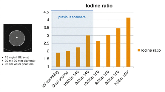

Fig. 2.3
DE iodine ratios for different DE acquisition techniques at 20 cm phantom diameter: kV switching 80 kV/140 kV, first generation DSCT at 80 kV/140 kV (Dual Source), second generation DSCT at 100 kV/140 Sn kV and at 80 kV/140 Sn kV (0.4 mm tin pre-filtration), third generation DSCT at 100 kV/150 Sn kV, at 90 kV/150 Sn kV, at 80 kV/150 Sn kV and at 70 kV/150 Sn kV (in this case, Sn means the use of 0.6 mm tin pre-filtration)
The DE iodine ratio for the SOMATOM Definition Flash at the standard x-ray tube voltage combination 100 kV/140 Sn kV is 2.25; the DE iodine ratio for the SOMATOM Force at the new standard x-ray tube voltage combination 90 kV/150 Sn kV is 3.0, this corresponds to an improvement of 33 %. When comparing the standard 90 kV/150 Sn kV scan mode of the SOMATOM Force with scan techniques relying on the use of 80 kV/140 kV without spectral shaping (such as e.g. kV-switching), the improvement with 90 kV/150 Sn kV is 58 %.
The DE iodine ratios at other phantom diameters are shown in Fig. 2.4, together with the measured image noise in virtual non-enhanced CT images at equal radiation dose. The CTDIvol values for the 10, 20, 30 and 40 cm phantoms (1.2, 2.5, 7.2 and 21.2 mGy) were kept constant at all voltage combinations used to scan the respective phantoms.
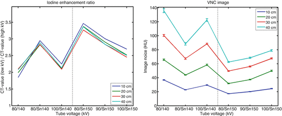

Fig. 2.4
DE iodine ratios (left) and image noise (in HU) in the virtual non-enhanced CT images (right) for different DE acquisition techniques at different phantom diameters. At each phantom diameter radiation dose was kept constant when using the different techniques. The lower the image noise in a virtual non-enhanced CT image, the better is the radiation dose efficiency of the respective DE technique
Image noise in virtual non-enhanced images is a good indicator for the radiation dose efficiency of a DE technique: the lower the image noise in the virtual non-enhanced images after DE material decomposition, the less radiation dose has to be used for DE scanning to obtain virtual non-enhanced images that may replace true non-contrast images. At equal radiation dose, noise is highest at 80 kV/140 kV, and lowest at the settings using 150 Sn kV. For the 40 cm phantom, image noise at 80 kV/140 kV without spectral shaping is 117 % higher than at 80 kV/150 Sn kV.
Spectral pre-filtration of the high-kV beam is therefore beneficial for DE CT at low radiation dose. Several authors have meanwhile demonstrated dual source DE CT scanning with no dose penalty compared to standard single energy CT. As an example, Schenzle et al. [10] report the feasibility of dual source DE CT without increasing radiation dose in chest CT. Moreover, the authors claim that contrast-noise ratio (CNR) can be doubled with optimized DE CT reconstructions. Thus, CT can be performed routinely in DE mode without additional dose or compromises in image quality. Bauer et al. [11] compare radiation dose and image quality of 64-slice CT and dual source DE CT for CT pulmonary angiography (CTPA). They conclude that the use of second generation DECT in 80 kV/140 Sn kV configuration allows for significant dose reduction with image quality similar to 120 kV CTPA. A comprehensive overview on radiation dose in DE CT can be found in [12].
Challenges
One challenge of dual source DE CT is the presence of cross-scattered radiation, i.e. scattered radiation from x-ray tube B detected by detector A and vice versa. Cross-scattered radiation – if not corrected for – can result in image artefacts and degraded CNR of the images [13].
The most straightforward correction approach is to directly measure the cross-scattered radiation in detectors A and B and to subtract it from the measured signal. This technique is implemented in the second generation DSCT. It requires additional detector elements on each detector outside the direct beam, see Fig. 2.5.
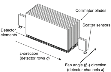

Fig. 2.5
Schematic diagram of a detector module with scatter sensors outside the direct beam. The center region consists of the primary detector pixels, positioned below the collimator blades of the anti-scatter collimator. The scattered radiation sensors, placed on both sides of the primary detector module, are equipped with collimator blades as well. The arrows indicate the z-direction (row direction) and the fan angle direction (channel direction)
An alternative to direct measurement is a model-based cross-scatter correction. The primary source of cross-scattered radiation is Compton scatter at the object surface. In the first generation DSCT, pre-stored cross-scatter tables for objects with similar surface shape are used for an on-line correction of the cross-scattered radiation in each measured projection. In the SOMATOM Force, an iterative cross-scatter correction based on a simplified Monte Carlo simulation of scatter in the actual scan object is applied.
While image artifacts caused by cross-scattered radiation can be significantly reduced by either model-based or measurement-based correction approaches, these corrections are often considered to come at the expense of increased image noise and reduced contrast-to-noise ratio (CNR) in the images. It has been demonstrated, however, that careful low pass filtering of the scatter correction term can efficiently mitigate the image noise increase without visually affecting image detail resolution or image contrasts [13]. CNR can in fact be increased beyond the values achieved without cross-scatter correction, and it approaches or sometimes even surpasses the CNR-performance of a comparable single source scan [13].
Another challenge of dual source DE CT is the 90° offset of projections acquired by both x-ray tubes at the same z-position. Because high-energy and low-energy projections are not simultaneously acquired at the same projection angle, raw data based DE algorithms are difficult to realize. DE algorithms are therefore image-based. It is often claimed that image-based methods are inferior to raw data based algorithms. However, under certain conditions which are typically fulfilled in modern CT-scanners, image based methods are practically equivalent for clinical tasks. One pre-requisite for image based material decomposition is the validity of the thin absorber model. If we use e.g. water and iodine as the basis materials for image based DE decomposition, the maximum x-ray attenuation of the iodine along any measured ray path is expected to be so small that it is valid to assume a linear contribution to the total attenuation. The thin absorber model holds for iodine samples with up to 5,000 HU·cm in water, corresponding to the clinical situation of an object with 200 HU iodine enhancement and 25 cm thickness. In clinical practice, this pre-requisite is violated only in extreme situations when very high concentrations of iodine are present, such as in CT nephrographic studies. As a second pre-requisite, both the CT-value of water and the CT-values of small iodine samples are expected to be independent from their position within the scanned object. DSCT scanners are therefore equipped with an optimized bowtie filter of sufficient beam hardening, and the approximately cylindrical patient cross-section has to be centered within the SFOV. In practice, electronics noise, scanner calibration, stability of emitted spectra, cone beam effects, and scattered radiation can have a larger impact on the obtained results than the raw data or image based analysis method.
A third challenge is the fact that moving objects, such as the heart, are seen by both detectors with an angular offset of about 90°. Motion artefacts in the corresponding A and B images can therefore be slightly different, which can affect the material decomposition of the dual energy images. In practice, however, this problem is not relevant thanks to the good temporal resolution of DSCT, and it can be further mitigated by non-rigid registration of A and B images.
Specific Solutions for Vascular and Cardiac Dual Source Dual Energy CT
For vascular dual source DE CT, i.e. for CT angiographic studies, dedicated scan protocols are available that aim at high scan speed by combining fast gantry rotation (0.25 s, 0.28 s or 0.33 s) with high spiral pitch >1. With the SOMATOM Force, a maximum scan speed of 276 mm/s can be realized in DE mode. For dedicated cardiac examinations, both ECG-triggered DE sequential “step-and-shoot” scanning and ECG-gated DE spiral scanning are provided, both at the fastest gantry rotation speed of the respective DSCT scanner. ECG-gated DE spiral scanning can be combined with ECG-controlled radiation dose modulation. ECG-triggered DE sequential scanning can react flexibly to arrhythmia and – at the user’s request – automatically repeat data acquisition at a given z-position, if an extra-systole occurs.
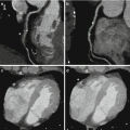
The temporal resolution for DE material decomposition is half the gantry rotation time (165 ms for first generation DSCT, 140 ms for second generation DSCT, 125 ms for third generation DSCT), because a complete half-scan sinogram has to be acquired by each measurement system to reconstruct both a low-kV and a high-kV image. In combined DE images (weighted addition of the low-kV and high-kV images) for coronary CT angiography evaluation, however, a temporal resolution of a quarter of the gantry rotation time (83 ms for first generation DSCT, 75 ms for second generation DSCT, 66 ms for third generation DSCT) can be restored by means of a hybrid image reconstruction technique. This way, obtaining information on the myocardial blood supply by DE evaluation does not come at the cost of reduced diagnostic performance of coronary CT angiography for stenosis detection. The hybrid reconstruction algorithm is based on superimposing two separately reconstructed images [14]. The first image is reconstructed by using a quarter-scan data segment from each x-ray tube similar to a dual source single-energy coronary CTA reconstruction. This image has a temporal resolution close to a quarter of the gantry rotation time, the coronary arteries are sharp, but it suffers from spectral artifacts and the CT-numbers are inconsistent, because raw data with different energies are mixed. The second image uses the full half-scan data segment from the low-energy tube (to maximize the iodine contrast). It is a smooth background image without spectral artifacts and with the correct CT-numbers of the low-energy scan, but due to the lower temporal resolution of trot/2 the borders of the moving structures of interest are less sharp. After reconstruction of these two initial images, a high pass filter is applied to the first image to maintain only the sharp high-contrast structures, and a corresponding low pass filter is applied to the second image to maintain the correct background signal, see Fig. 2.6. Both filtered images are then linearly superimposed to the final image, combining high temporal resolution of the coronary arteries with a high-contrast, low-noise background. A clinical example is shown in Fig. 2.7.
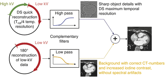
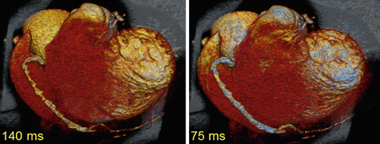

Fig. 2.6
Schematic diagram of the hybrid reconstruction algorithm to restore the maximum temporal resolution in a combined dual source DE image for optimized visualization of the coronary arteries

Fig. 2.7
Clinical example of a second generation DE coronary CT angiography with standard half scan reconstruction (left) and with the hybrid reconstruction algorithm to restore the maximum temporal resolution in a combined dual source DE image (right) (Image courtesy of Centre Thoracique, Monaco)
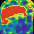
Coronary CT angiographic images may suffer from beamhardening artifacts between aorta and left ventricle which affect DE decomposition, if e.g. an iodine image of the myocardium is computed to evaluate the local blood supply. These beamhardening artifacts can mimic local perfusion defects. It is sometimes claimed that only raw-data based dual energy approaches are able to synthesize material-selective or pseudo mono-energetic images free of beam-hardening artifacts, and that image based dual energy approaches are limited in accurate iodine quantification. DSCT scanners, however, can make use of an efficient iterative correction algorithm optimized to correct for iodine-related beamhardening, which is applied prior to the image based material decomposition. It significantly reduces beamhardening artifacts in the low-kV and high-kV images and facilitates precise computation of material-specific or pseudo mono-energetic images, see Fig. 2.8.
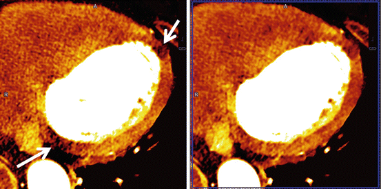

Fig. 2.8


Dual source DE iodine image of the myocardium, acquired on a SOMATOM Force (temporal resolution 125 ms). Left: without beamhardening correction. Beamhardening artifacts along a line between aorta and left ventricle (arrows) can mimic perfusion defects (darker zones with less iodine enhancement). Right: with iterative beamhardening correction. The beamhardening artifacts are significantly reduced
Stay updated, free articles. Join our Telegram channel

Full access? Get Clinical Tree


