Arjun Nair, Zelena A. Aziz, David M. Hansell
Techniques in Thoracic Imaging
Chest radiography and computed tomography (CT) remain the imaging tests of choice for the evaluation of respiratory disease. The basic technique of chest radiography has changed little over the past century, but continuing developments in image receptor technology have resulted in the more efficient acquisition of chest radiographs with the benefit of a lower radiation dose. Radiographs are now mainly produced in digital format, thus facilitating their incorporation into picture archiving and communications systems (PACS). Evolving CT technology has meant that multidetector row CT (MDCT) systems have largely replaced single-detector CT. Newer dual-energy CT (DECT) systems may provide new applications, although these have not yet been fully validated. These developments have resulted in larger volume CT data sets increasingly becoming the norm. Protocols for MDCT continue to be developed and refined to ensure the correct balance is struck between the imperatives of obtaining adequate information and dose minimisation. Ultrasound and magnetic resonance imaging (MRI) may have specific but limited roles in the investigation of thoracic disease. Positron emission tomography (PET) fused with CT (PET-CT) now has an established role in the investigation of neoplastic disease, enabling the simultaneous assessment of metabolic function, anatomical location and unsuspected extrathoracic metastatic disease. PET and PET-CT are considered separately in Chapter 6.
Chest Radiography
Equipment Considerations
Chest radiography remains the commonest diagnostic radiographic procedure. Chest radiographs were traditionally acquired with conventional film-screen radiography systems that provide, at low cost, good image quality and high spatial resolution.1,2 However, film-screen radiography is limited by a relatively narrow exposure range and consequent high retake rate, as well as inflexibility in image display and manipulation.1 The exponential advances in computational power, storage capacity and detector technology have led to the replacement of film-screen radiography by PACS and digital imaging systems in most modern imaging departments.
Early digital imaging systems introduced over 30 years ago (generally termed ‘computed radiography’ (CR)) used a photostimulable phosphor image receptor plate,3 and continue to be used in some departments because of their compatibility with conventional radiography equipment. However, CR systems have largely been superseded by direct radiography (DR) systems (Table 8-1). DR systems employ either direct or indirect methods for converting X-ray photons into electrical charges, thereby generating an electrical signal that can be read directly.4 Direct conversion may be achieved by photoconductors within flat-panel detectors (most commonly amorphous selenium), or using a selenium drum. Indirect conversion involves the use of a scintillator associated with either a charge-couple device (CCD) or flat-panel detector (FPD). Scintillators most commonly use thallium-doped caesium iodide-based, or more recently gadolinium-based compounds.
Both CR and DR systems offer many advantages over conventional film-screen radiography. Chief among these is the wide dynamic range or latitude of the image plate; consequently, exposure errors are reduced and the need for repeat examinations is lessened. Also, both CR and DR systems employ reusable detectors, manual optimisation of the display features desired for the anatomical part selected can be performed immediately and there is more efficient image archiving, retrieval and transmission when integrated into PACS. While there are conflicting reports with respect to dose and image quality for CR imaging of the thorax as compared with conventional radiography,1,5,6 DR systems undoubtedly offer superior image quality compared with both CR and film-screen combinations, with the added advantages of rapid image display and generally higher detector quantum efficiency. The latter efficiency allows a significant reduction in exposure, and consequently in effective dose.7 Among DR systems, indirect conversion FPDs provide the highest image quality.
Additional Radiographic Views
Frontal and lateral projections of the chest are adequate for most purposes. Other radiographic views are increasingly less frequently performed because of the ready availability of cross-sectional imaging. One projection that is still occasionally used is the lateral decubitus view, taken as a frontal projection with a horizontal beam and the patient lying on his/her side. It may be used to identify an effusion that is not visible on an erect chest radiograph, to demonstrate the movement of fluid in the pleural space or to localise or confirm an equivocal opacity seen on a frontal projection, especially when CT is unavailable.
Portable supine lateral shoot-through radiographs can be valuable in identifying suspected pneumothorax in critically ill patients unsafe for CT.8 Less commonly, expiratory radiographs may be performed to enhance visualisation of pneumothoraces, but the real value of this practice has been questioned.9
Radiographs exposed in expiration may be valuable in the investigation of air trapping, particularly in paediatric practice in the context of a suspected inhaled foreign body.10
Portable Chest Radiography
The imaging problems associated with portable chest radiography are (A) scattered radiation; (B) the inability of the radiograph to capture all relevant information; and (C) the lack of control over the overall optical density of the resulting image when there is slight over- or under-exposure. Additionally, the shorter focus–detector distance results in undesirable, and sometimes misleading, magnification of structures. High kilovoltage techniques cannot be used because portable machines are unable to deliver a sufficiently high kilovoltage, and as the maximum current is limited, long exposure times are needed, increasing movement artefact. CR systems provide solutions to some of the limitations of portable chest radiography by controlling optical density and contrast, but are unable to overcome the problem of scatter. CR systems remain the most widely used portable radiography system.
Portable DR detectors using FDPs with gadolinium-based scintillators have been available since 2001.11 Despite this, FDP detectors have not yet been widely adopted because of (A) prohibitive costs, and (B) the hitherto restricted positioning of DR detectors in a portable bedside setting. However, an increasing array of portable DR detectors is now being made available, including those that can be integrated into existing CR cassettes for flexible positioning, and those with wireless transmission capabilities to allow immediate transfer to PACS,4,12 which may substantially improve technologists’ workflow.12 Such developments are likely to encourage the uptake of portable DR systems in the near future.
Novel Radiographic Techniques
The new techniques of digital tomosynthesis, dual-energy subtraction radiography and temporal subtraction radiography have potential clinical application, chiefly for nodule detection to varying degrees, but at present are confined mainly to research studies.
Digital tomosynthesis of the chest involves the capture of a series of radiographic acquisitions with a digital detector system and computer-controlled apparatus, from which an unlimited number of section images at arbitrary depths and focus can be reconstructed.13 In this way, an object such as a pulmonary nodule may be rendered more conspicuous, with an exposure equivalent to that of a single film-screen lateral chest radiograph,14 and therefore with a dose substantially lower than that of CT. Preliminary data suggest improved sensitivity as compared with standard chest radiography for the detection of pulmonary nodules.14,15
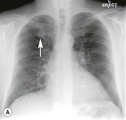
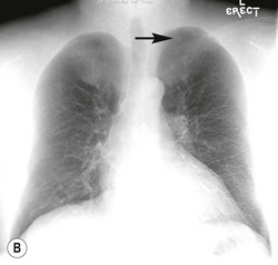
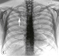
Dual-energy subtraction radiography is essentially a bone suppression technique that takes advantage of the differential attenuation of X-ray photons of high atomic number materials (such as calcium and iodine) at different photon energies.13 Such differential attenuation causes the contrast from calcium and bone in a high kVp image to be reduced. As such, subtraction of the low-energy from the high-energy image allows subtraction of obscuring bony structures, potentially increasing pulmonary nodule conspicuity (Fig. 8-1). Low- and high-kVp images can be generated in two ways. First, a single shot exposure, using a two-panel storage phosphor detection system with a copper filter, can be used to generate low- (usually 60) and high- (usually 120) kVp exposures, which can then be subtracted from each other. Alternatively, digital detectors are used to capture a sequential exposure, first at low and then high tube voltages, in a short interval.16
Temporal subtraction radiography involves the subtraction of a current and a previous radiograph to generate a difference image, so that any temporal change (such as a new lesion) is made more conspicuous. This technique relies heavily on co-registration of the two images using computer-generated techniques.16
Computed Tomography of the Thorax
The introduction of spiral (helical) CT in the early 1990s constituted a fundamental evolutionary step in the ongoing refinement of CT imaging, replacing the discontinuous acquisition of data in conventional CT with volumetric data acquisition. In 1998 several CT manufacturers introduced MDCT systems, which provided considerable improvement in acquisition speed, coverage and temporal and spatial resolution.17–19 These systems typically offered simultaneous acquisition of four sections with a gantry rotation time of as low as 0.5 s. Since then, there has been further rapid improvement in CT performance with increased numbers of detector rows and faster tube rotation; currently, systems with up to 320 active detector rows are available.20 Rotation times of the X-ray tubes have decreased from 0.5 to 0.33 s per rotation. Recent developments in CT technology have not decreased this rotation time further, but instead use novel methods for increasing temporal and spatial resolution, with either dual-source technology (with two X-ray sources mounted at 90° to each other), a ‘flying focal spot’ (converting a 128-detector row array into a virtual 256-detector row array), or wide-area detectors, effectively providing 320-detector row coverage.21 The faster data acquisition enables not only better coverage in a single breath-hold but also results in a significant reduction in patient movement artefacts. In paediatric practice this has meant less frequent need for sedation.22
The introduction of MDCT has expanded the clinical indications for CT; these are summarised in Table 8-2. MDCT systems permit reconstructions of varying slice thickness by collimating and adding together the signals of neighbouring detector rows, with overlap between these rows if necessary. Hence, from the same data set, both narrow sections (0.6–1.25 mm thickness) for high spatial resolution detail or three-dimensional (3D) post-processing and wide sections (2.5–5 mm) for better contrast resolution or quick review can be produced. The convenience of a single protocol is particularly useful for patients with suspected focal and interstitial lung disease. Thin section reconstructions are recommended for volumetric assessment23 and characterisation24 of pulmonary nodules, the evaluation of interstitial lung disease and the evaluation of pulmonary embolism,25 whereas 3- to 5-mm reconstructions are usually adequate for the initial assessment of mediastinal masses and for lung cancer staging studies. In younger patients, however, a more critical approach should be adopted with the CT examination being tailored to the specific clinical question being asked (e.g. interspaced sections when possible), to avoid unnecessary radiation dose (see section on radiation dose reduction strategies in CT, Chapter 1).
TABLE 8-2
Indications for CT of the Chest

The introduction of 16- and 64-detector MDCT systems allowed the goal of truly isotropic imaging to be realised: each image data element (voxel) is of equal dimension in all three axes, and forms the basis for allowing image display in any arbitrarily chosen imaging plane. The acquisition of volumetric high-resolution data has permitted new methods of 2D and 3D reconstruction that can complement conventional axial image review, particularly in the display of airways and vascular structures. Furthermore, isotropic imaging has facilitated the development of computer-aided detection and diagnosis systems for the detection and evaluation of pulmonary nodules26,27 and pulmonary emboli,28 as well as automated quantification of disease processes, most notably emphysema.29
Table 8-3 summarises the various post-processing techniques used in evaluating thoracic disease.
TABLE 8-3
Post-Processing Techniques and Examples of Clinical Application
| Technique | Technical Considerations | Examples of Use |
| Multiplanar and curved multiplanar reconstructions (MPR and CMPR) | 2D techniques that provide alternate viewing perspectives, usually with conventional window settings. Images are obtained by a reordering of the voxels into 1-voxel-thick tomographic sections, excluding those voxels outside the imaging plane | Evaluation of the large airways and pulmonary emboli, particularly for interpretative difficulties on axial sections due to either partial volume averaging or the inability to differentiate periarterial from endoluminal abnormalities |
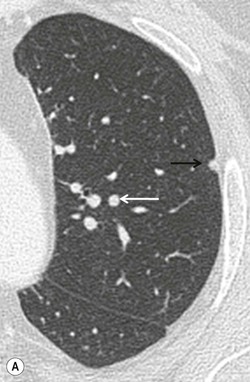
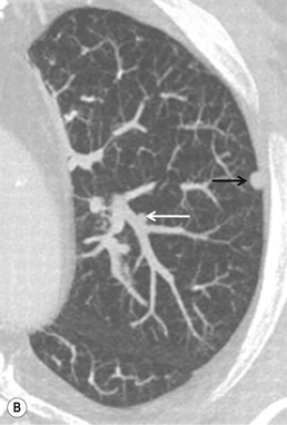
| Maximum intensity projection (MIP) | A ray is cast through the CT data and only data above an assigned value are displayed, thus reducing all data in the line of the ray to a single plane. Sliding slabs of 5–10 mm are commonly used | Mainly used in vascular imaging and in the evaluation of micronodular disease (more accurate identification of nodules versus vessels, and more precise characterization of nodule distribution) (Fig. 8-2) |
| Mininum intensity projection (MinIP) | Similar to MIP, but only data below an assigned value are displayed and thus it is best suited for showing areas of low density | May improve conspicuity of subtle density differences of lung parenchyma and therefore highlight regions of emphysema or air trapping |
| Shaded surface display (SSD) | Data reformatted around a threshold that defines the interface of tissues. SSD does not reveal any internal detail | Evaluation of airway abnormalities |
| Volume rendering | Histogram-based classification is applied to attenuation values in the entire CT data set. CT attenuation can be mapped to brightness, opacity and colour to display a structure of interest. Voxels partially filled with a density of interest are also included. The resultant images contain depth information whilst maintaining 3D spatial relationships | Used in angiographic examinations and also to evaluate large airway abnormalities |
| Virtual bronchoscopy | Surface rendering and volume rendering are used to produce endoscopic simulations of the airway | Virtual endoscopic or perspective volume rendering images are not widely applied as they seldom give information that cannot be obtained by MPR. However, virtual CT bronchoscopy can provide a view ‘through’ an obstructing lesion to visualise the airway distal to it, which may not be possible with conventional bronchoscopy |
| Computer-aided detection | Computerised complex pattern recognition employing a combination of image processing, segmentation and pattern classifiers to identify lesions of interest | Detection and volumetric assessment of pulmonary nodules and pulmonary emboli |
| Quantitative lung parenchymal assessment | Quantification of parenchymal lung density using techniques such as density masks and histogram analysis to allow objective parenchymal assessment | Emphysema quantification |
| Dual-energy CT pulmonary blood volume assessment | Generation of iodine maps that act as a surrogate of lung perfusion and therefore of pulmonary blood volume on dual-energy CT | Assessment of perfusion defects in acute and chronic pulmonary thromboembolism |
| Dual-energy CT virtual unenhanced imaging | Removal of iodine from post-contrast dual-energy acquisitions to generate virtual unenhanced images | Evaluation of apparent enhancement in pulmonary nodules without need for two separate pre- and post-contrast CT acquisitions |
Dual-Energy CT
The concept of DECT was first explored in the 1970s although initial efforts were hampered by limitations in the CT hardware and computational power available at the time. New CT technology has permitted the development of DECT systems over the past seven years. The principles underpinning DECT are the same as for dual-energy subtraction radiography (discussed earlier). DECT allows materials to be differentiated by analysing their attenuation properties at different photon energies, using the material decomposition theory.30 This theory is particularly applicable to high atomic number materials such as iodine or calcium owing to the photoelectric effect, as they exhibit different degrees of attenuation at different energies.
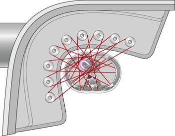
Different methods for achieving DECT acquisitions are currently used. A dual-source CT system with two X-ray tubes mounted at 90° to each other can provide a dual-energy acquisition by operating the tubes at different kilovoltages (typically 80 or 100 kVp and 140 kVp, respectively)31 (Fig. 8-3). DECT imaging with single-source CT currently uses either rapid switching between two kilovoltages32 or a dual-layer (‘sandwich’) detector, with different detector layers absorbing the different energy spectra.33
Regardless of the acquisition technology employed, these DECT systems are all able to generate material-specific image data sets or subtraction images, from a single CT acquisition. In doing so, the need for pre- and post-contrast imaging can be obviated, thus reducing dose while simultaneously avoiding problems arising from misregistration between acquisitions before and after intravenous contrast agents. For example, material differentiation of iodine makes it possible to create a virtual unenhanced image data set. This may have potential clinical application in pulmonary nodule characterisation,34 for example. Alternatively, by creating an ‘iodine only’ image data set, a map of pulmonary blood volume can be generated from a contrast-enhanced thoracic DECT acquisition. The latter may demonstrate perfusion defects in acute and chronic pulmonary thromboembolism35–37 analogous to, and potentially comparable with, that depicted by perfusion scintigraphy.35,37 While promising, these potential clinical applications of DECT in thoracic imaging have yet to undergo extensive validation.
Dose Considerations
It is important to appreciate some fundamental principles of CT acquisition and factors affecting radiation dose, before considering strategies for dose reduction.
In a CT X-ray tube, a small area on the anode plate emits X-rays that penetrate the patient and are registered by the detector. A collimator between the X-ray tube and the patient, the pre-patient collimator, is used to shape the beam and establish the dose profile. In general, the collimated dose profile is a trapezoid in the longitudinal direction, resulting in umbral and penumbral regions within the area of coverage. In the umbral region, X-rays emitted from the entire area of the focal spot fall on the detector; however, in the penumbral regions at the edge of the beam, only a part of the focal spot illuminates the detector—the pre-patient collimator blocking off other parts.
Despite its undoubted clinical benefit, MDCT carries an increased radiation exposure burden compared with conventional single-slice CT. The increase in radiation arises primarily as a result of wasted radiation dose, due to decreased geometric efficiency of MDCT. Geometric efficiency indicates the proportion of the X-ray beam used in image formation. Lower efficiency thus means that increased doses will be required to maintain similar image quality.38
Stay updated, free articles. Join our Telegram channel

Full access? Get Clinical Tree


