Chapter 30 The diagnostic X-ray tube
Chapter contents
30.1 Aim
The aim of this chapter is to discuss the factors involved in the construction of diagnostic X-ray tubes.
30.2 Introduction
1. The heat deposited in the anode during an X-ray exposure is spread over a larger area and so there is a smaller temperature rise at the anode surface.
2. The cooling characteristics of the rotating anode are superior to those of the stationary anode and this effective dissipation of heat means that larger loads can be applied without causing thermal damage to the target.
The stationary anode tube has a very low rating (see Ch. 31) and is only found in dental and some portable X-ray units. These units are connected to a 13-amperes mains supply. This limits the amount of electrical power that can be applied to it, preventing overloading of the tube.
30.3 Construction of X-ray tubes
The X-ray tube consists of two main components: the insert, which is mounted inside the tube shield.
These components and the light-beam diaphragm (we will discuss its role later in this chapter) are shown in Figure 30.1 (see page 222). The components of this tube are discussed individually in Section 30.5. Although the inserts for the rotating anode tube and the stationary anode tube differ substantially, the shields for both types of tube are very similar in design and function.

30.4 Construction of the tube shield (housing)
• There must be no danger of electrical shock if the shield is touched during operation of the X-ray tube.
• No significant amounts of radiation should escape from the shield other than the radiation necessary for taking the radiograph.
• The shield must give secure support to the X-ray tube insert, the high-tension cables and the connecting cables within the shield.
• Adequate insulation must be provided between the insert and the tube shield to avoid electrical breakdown.
• There must be adequate cooling of the insert and facilities to allow expansion of the cooling oil.
• There must be facilities at the tube port to allow adequate filtration of the emergent beam so that low-energy radiations may be removed from the beam.
As can be seen from this list, the shield must satisfy many requirements. A schematic diagram of the shield for a rotating anode X-ray tube is shown in Figure 30.1. Note that the insert is held in position by a support at the anode end.
The metal casing surrounding the insert is made of either aluminium or steel and is lined with about 3 mm of lead to provide sufficient radiation protection. This housing is filled with pure oil that acts as an electrical insulator and as a coolant. A neoprene diaphragm at one end of the shield allows for expansion of the oil when the oil is heated. The assembly is usually fitted with a microswitch, which will prevent further exposures if the oil is very hot. Within the casing there is a radiolucent window – the tube port – which will allow the useful beam of radiation to leave the tube via the light-beam diaphragm.
30.4.1 Electrical safety
Electrical safety is designed around four basic principles:
1. Insulation of live components.
2. Earthling of component housings.
3. Restricted access to live components.
4. Isolation of the circuits from the mains supply when not in use.
All of the above are utilized in the design of the X-ray tube. Insulation exists between the live components and the housing in the form of the oil in the housing. The resistance of an insulator (and so its insulating properties) diminishes as the temperature of the insulator increases and so the role of the oil in heat dissipation is also important from the point of view of electrical safety.
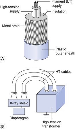
The tube shield is connected to earth via the outer braiding of the high-tension cables (Fig. 30.2) and so the casing will always remain at earth potential. If a live wire within the casing becomes disconnected and touches the shield, then the current will readily flow to earth and the casing will present minimal electrical hazard to someone touching it at the time.
30.4.2 Radiation safety
Radiation safety is important for the operators of X-ray equipment and for patients and others who may be in the vicinity at the time of making an X-ray exposure. The lead lining of the tube housing (Fig. 30.1) limits the radiation leakage from the tube and so provides protection to both the operator and the patient. It should be borne in mind that X-rays are emitted in all directions from the focus on the anode, but only those which pass through the tube port are allowed to leave the housing. The anode itself has a high absorption and so the lead lining at the anode end of the shield is often absent or thinner than at the cathode end.
The radiation leakage rate from the tube is normally measured at a distance of 1 metre from the housing and should not exceed an air kerma of 1.00 milligray per hour, measured at a distance of 1 metre from the focus (for definitions of the kerma and the gray, see Ch. 27). Any break in the lead lining will result in radiation leakage from the tube, so the leakage levels should be checked at regular intervals as part of the quality checks on the X-ray unit.
Radiation safety means exposing the patient only to the minimum dose necessary to produce a radiograph of acceptable quality. As we saw in Chapter 21, the spectrum of X-rays produced at the target is a continuous spectrum containing a mix of low-, medium- and high-energy photons. Some of the photons have very low energy and will not be able to pass through the patient to reach the image receptor. These photons would contribute to the patient dose but not to the image production. Some of these are removed by the glass envelope of the insert and the oil as the beam passes to the tube port. This is known as the inherent filtration of the tube. Further filtration takes place through the aluminium filters placed at the tube port (Fig. 30.1). These are known as added filtration. Thus, the total filtration of the beam is determined by the inherent filtration plus the added filtration. Details of this information are frequently marked on the end of the shield.
Scattered radiation contributes to the patient dose and the operator dose and causes degradation in the radiographic image quality. As we have seen in Chapter 23, the amount of scatter produced at a given set of exposure factors is dependent on the volume of tissue irradiated. The volume can be reduced by reducing the area irradiated using a light-beam diaphragm (Fig. 30.1). This also means that parts of the body not required on the radiograph can be protected from radiation. In this way, adequate collimation using a light-beam diaphragm (or cones) will reduce the patient dose and the operator dose and produce an improvement in the image quality.
30.5 Construction of the rotating anode tube insert
30.5.1 Insert envelope
X-ray production is at its most efficient when a vacuum exists between the cathode and the anode of the X-ray tube, so these structures are enclosed within an evacuated metal or heatproof glass envelope, which must be sufficiently strong to preserve this vacuum. Where glass envelope is used, it is joined to the anode spindle at one end and to the nickel cathode support at the other end by re-entrant seals – so called because the glass is shaped to point inwards at the area of contact. Slightly different glass seals are used at each end so that the thermal expansion of the glass is similar to that of the metal used in the construction of the anode spindle and cathode. This reduces the stress on the glass when the insert is hot and so limits the chance of cracking. The glass must be a good electrical insulator or a substantial current will flow through it when the high potential difference is applied between the anode and the cathode. However, electrical charges are built up on the inside of the glass during operation and so the glass must have sufficient electrical conductivity to allow these to leak away, usually between exposures, avoiding the build up of high amounts of static charge. The glass is gently rounded so that there are no sharp corners, which would allow the build up of high amounts of static charge (see Ch. 6).
During operation of the X-ray tube, a thin film of tungsten will be deposited on the inside of the envelope as a result of the release of tungsten vapour from the filament and the target. This film acts as a filter to emergent radiation, and where a glass envelope is used, may eventually cause electrical breakdown within the tube as it can act as an electrical conductor around the inside wall of the glass envelope. If this happens, the tube is classed as ‘gassy’ and is of no further use. The rate of tungsten vaporization can be reduced by not keeping the tube in the ‘prep’ mode (see Sect. 29.2) any longer than is required and by keeping exposures well within the rating of the tube (see Ch. 31).


Stay updated, free articles. Join our Telegram channel

Full access? Get Clinical Tree


