Chapter 12 The motor principle
Chapter contents
12.2 Introduction and definition of the motor principle 71
12.3 Direction and magnitude of the force on the conductor 72
12.4 Convention for the direction of the force 72
12.5 Interaction of two electromagnetic fields 73
12.7 The AC induction motor 74
12.8 Magnetic deflection of an electron beam 75
12.9 The motor principle in radiography 76
12.1 Aim
The aim of this chapter is to consider the motor principle. The application of this principle to the direct current (DC) motor and the alternating current (AC) induction motor will be considered, as will the magnetic deflection of electrons. Finally, the relevance of these to radiography will be discussed.
12.2 Introduction and definition of the motor principle
In Chapter 9, we considered the topic of electromagnetism where a magnetic field was produced by an electric current. This chapter considers what happens when an electromagnetic field is created in the presence of another magnetic field. If we consider two bar magnets lying in close proximity to one another, then (depending on their orientation) a force of repulsion or attraction will exist between them (see Ch. 8). If one of the bar magnets is now replaced by a solenoid (see Sect. 9.6), we would expect a force between the solenoid and the bar magnet when an electric current is passed through the solenoid, since it behaves like a bar magnet under these circumstances. This force will cause the solenoid to move if it is free to do so. When the current is switched off, the magnetic field due to the solenoid disappears and so does the force between it and the magnet. This interaction between electromagnetism and another magnetic field is known as the motor principle (or motor effect) and may be formally defined:
The principle of the electric motor is that it converts electrical energy into kinetic energy (mechanical energy) through the interaction of the two magnetic fields.
12.3 Direction and magnitude of the force on the conductor
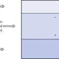
Consider a length L of straight wire which is carrying an electric current I, the whole wire being placed in a uniform magnetic flux density B, as shown in Figure 12.1. In this diagram, it is assumed that the direction of B and of the wire are both in the plane of the paper. Experimentally, the following results are observed:
• The direction of the force on the wire is always into or out of the paper, i.e. at right angles to the direction of B and I.
• The direction of the force on the wire is reversed if the current is reversed.
• The magnitude of the force is proportional to:


 the sine of the angle between the direction of B and I, i.e. sin θ in Figure 12.1. Thus, the force on the wire is at its maximum when the wire is at right angles to the field (sin 90°=1) and zero when the wire is parallel to the field (sin 0°=0).
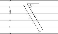
Combining the factors in the last bullet point above, we have:

where the force, F, is in newtons, B in tesla, I in amperes and L in metres.
The findings discussed above may be used to define the tesla as follows:
The direction of the force on the current-carrying conductor may be obtained using the appropriate rule or convention. As we saw before, in Chapter 10, Fleming’s right- and left-hand rules were produced to deal with ‘conventional current’ and not electron flow. To avoid confusion, a different convention will be presented to calculate the direction of the force on the current-carrying conductor.
12.4 Convention for the direction of the force
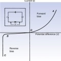
Consider the situation shown in Figure 12.2A. Here a wire is carrying an electric current such that the electrons are flowing away from the eye of the observer into the paper. The magnetic field, H, produced by this current is in an anticlockwise direction, as shown. If an external magnetic field, B, is applied to the wire as shown, it is found that the wire experiences a force, F, which pushes it to the right. Figure 12.2B shows the convention which will be used to determine the direction of the force – this is similar in many ways to the convention used in Section 10.6 to determine the direction of the induced current. The direction of the force can be determined as follows:
1. Mark the position of the wire, and draw the direction of electron flow and the magnetic field around it. In Figure 12.2B, this is an anticlockwise magnetic field as the electrons are flowing away from us.
2. Align one of the lines of force from the external magnetic field (B) so that it touches the field around the wire at the point where both fields are in the same direction. This occurs at point A in Figure 12.2B
3. Now draw a line from this point through the wire (AF
Related posts:
Stay updated, free articles. Join our Telegram channel

Full access? Get Clinical Tree


