The Neonatal Head
Tara K. Cielma
Anjum N. Bandarkar
|

OBJECTIVES
Review developmental anatomy of the brain and intracranial vascular structures.
Identify the sonographic appearance of the normal brain in neonates and infants.
Describe the systematic evaluation of the neonatal brain.
Discuss Doppler evaluation of intracranial vessels.
Describe the physiologic and maturation differences in the sonographic appearance of the preterm and term neonatal brain.
Illustrate ischemic injury of the preterm and term infant.
Identify the risk factors for the development of an intracranial hemorrhage (ICH) and illustrate the sonographic appearance of ICH.
Describe the mechanism, etiologies, and sonographic appearance of hydrocephalus.
Identify types of traumatic hemorrhage including birth trauma and non-accidental injury.
Identify ultrasound findings in the setting of congenital infections.
List common pathologies including congenital malformations of the brain that can be visualized sonographically.
Describe the evaluation of cranial sutures to assess for craniosynostosis.
KEY TERMS
agenesis of the corpus callosum
anterior cerebral artery
cerebellar hemorrhage
Chiari malformation
coarctation of the lateral ventricle
cytomegalovirus
Dandy-Walker complex
germinal matrix hemorrhage
holoprosencephaly
hydrocephalus
hypoxic-ischemic encephalopathy
increased intracranial pressure
intracranial hemorrhage
macrocephaly
middle cerebral artery
periventricular leukomalacia
porencephaly
prominent periventricular blush
resistive index
subarachnoid space
TORCH complex
vein of Galen malformation
GLOSSARY
cerebellum
posterior portion of the brain composed of two hemispheres; lies below the tentorium
posterior portion of the brain composed of two hemispheres; lies below the tentorium
cerebral spinal fluid (CSF)
surrounds the brain and the spinal cord to protect the brain and spinal cord from injury
surrounds the brain and the spinal cord to protect the brain and spinal cord from injury
cerebrum
largest section of the brain; divided into two hemispheres joined by the corpus callosum
largest section of the brain; divided into two hemispheres joined by the corpus callosum
choroid plexus
echogenic cluster of cells located within the lateral ventricles responsible for the production of CSF
echogenic cluster of cells located within the lateral ventricles responsible for the production of CSF
corpus callosum
largest white matter structure in the brain; contains nerve tracts that allow communication between the right and left hemispheres of the brain
largest white matter structure in the brain; contains nerve tracts that allow communication between the right and left hemispheres of the brain
falx cerebri
fold of dura mater that divides the two hemispheres of the brain
fold of dura mater that divides the two hemispheres of the brain
fontanelle
soft spot between the cranial bones; anterior, posterior, and mastoid fontanelles are used as acoustic windows during sonographic examination of the neonatal brain
soft spot between the cranial bones; anterior, posterior, and mastoid fontanelles are used as acoustic windows during sonographic examination of the neonatal brain
gyri
various infolds of the cerebral cortex, surrounded by sulci
various infolds of the cerebral cortex, surrounded by sulci
hypoxia
lack of oxygen
lack of oxygen
infant
human baby 1 month to 1 year of age
human baby 1 month to 1 year of age
meninges
membranous coverings of the brain and spine
membranous coverings of the brain and spine
neonate
human baby less than 1 month of age
human baby less than 1 month of age
porencephaly
cyst or cavity in the brain usually as a result of a destructive lesion
cyst or cavity in the brain usually as a result of a destructive lesion
sulci
linear structures that separate gyri
linear structures that separate gyri
suture
fibrous, immovable joints that connect the skull bones
fibrous, immovable joints that connect the skull bones
thalamus
paired ovoid structures in the central brain responsible for relaying nerve impulses and carrying sensory information into the cerebral cortex
paired ovoid structures in the central brain responsible for relaying nerve impulses and carrying sensory information into the cerebral cortex
Cranial sonography has evolved into a vital clinical tool and is the primary modality for screening, monitoring, and follow-up of intracranial hemorrhage (ICH), hydrocephalus, ischemic lesions, and congenital malformations of the neonatal and infant brain. Its widespread utilization is the result of its proven diagnostic value, improved sensitivity and specificity, bedside availability, nonionizing nature, and its cost-effectiveness compared with other imaging modalities.
The overall aim of this chapter is to provide an introduction to cranial sonography for sonographers of all experience levels. The chapter discusses exam indications, scanning protocols, sonographic anatomy, normal variants, and common intracranial pathology and anomalies. For a more comprehensive study of intracranial anomalies, there are several texts the reader should reference.1,2
TECHNIQUE
The anterior fontanelle is the primary acoustic window to image the brain. The closure of the anterior fontanelle begins at about 9 months of age and is usually complete by approximately 15 months of age. However, the fontanelle may remain patent in patients with extreme prematurity and in conditions like osteogenesis imperfecta, and hypophosphatasia. Routine images are obtained in coronal and sagittal planes. The posterior fontanelle (PF), mastoid (posterolateral) fontanelle (MF), and sphenoid fontanelle have shown considerable diagnostic value as adjuvant imaging approaches to the routine anterior fontanelle approach. The squamosal portion of the temporal bone allows interrogation of the circle of Willis. The foramen magnum provides visualization of the upper spinal canal in patients with Chiari malformation. An illustration of their clinical utility will be discussed further in this chapter.
A small-footprint, high-frequency, 7-to-10-MHz phased-curved array or sector transducer is typically used to image the neonatal brain. A lower-frequency (5 to 7 MHz) transducer may be needed for older infants with closing fontanelles or infants with a large amount of hair. Some infants may require a lower frequency, such as 4 MHz, to penetrate the temporal bone for transaxial Doppler imaging. A small-footprint, high-frequency linear transducer (9 to 18 MHz) is useful for imaging superficial structures, such as the superior sagittal sinus (SSS), superficial cortex, or the extracranial space around the convexity of the brain.3 Coupling gel and standoff pads may be used to achieve optimal skin-to-transducer contact to characterize structures in the near field. Color and spectral Doppler are utilized to assess intracranial hemodynamics.
Preterm infants (defined as delivery prior to 36 weeks of gestation) in the intensive care nurseries are at high risk for infections because of their immature immune systems. Transducers and cables must be cleaned thoroughly between each patient. Proper hand-washing technique, adherence to isolation protocols, and the use of single-use gel packets will help minimize the spread of infection. Before proceeding with the scan, the examiner needs to communicate with the nurse in charge of the infant to discuss any potential complications that may arise during scanning and to solicit help with ventilator tubes or other equipment that may need to be rearranged in order to access the fontanelles. There are also some procedural precautions that need to be observed in order to prevent additional stress on the preterm infant. These precautions include limiting head and neck movement to minimize the risk of dislodging critical airway support; minimizing pressure to the anterior fontanelle to avoid bradycardia; and maintaining thermal regulation to prevent heat loss. Opening the isolette doors should be avoided when possible. Scanning through the portholes of the isolette and the use of prewarmed gel can help the infant maintain thermal stability during the sonography examination.
NORMAL BRAIN ANATOMY
The brain and spinal cord comprise the central nervous system (CNS). Three protective membranes, called meninges, cover and protect the brain and spinal cord from injury, to allow the passage of CSF and to support vascular structures. They consist of the dura mater, arachnoid mater, and pia mater. The dura mater is the outer layer and the most resilient of the three. It attaches to the inside of the cranial vault and partitions the intracranial space through folds into separate compartments. The arachnoid space forms the middle layer, forming a bridge around the cortical sulci. The pia mater surrounds the innermost surface of the cerebral cortex, and closely follows the contours of the gyri and sulci.
Cerebrospinal Fluid
The CSF surrounds the brain and the spinal cord. Largely produced by choroid plexus (CP), this fluid acts like a buffer to help cushion the brain and spinal cord from injury, removes waste products, and serves to regulate intracranial pressure. The brain maintains a balance between the amount of CSF that is generated and the amount that is absorbed.
Fontanelles
The anterior fontanelle (also known as bregma) is formed at the junction of the coronal, sagittal, and frontal sutures. Closure occurs at approximately 9 to 15 months of age. The PF is formed by the junction of the lambdoid and sagittal sutures and may be palpated above the level of the occipital protuberance. Closure occurs at approximately 2 to 6 months of age. The mastoid fontanelle (MF) (also known as posterolateral) is located at the junction of the squamosal, lambdoidal, and occipital sutures. Closure occurs at approximately 6 to 18 months of age. The sphenoid fontanelle (also known as anterolateral) is located at the intersection of the sphenoid, parietal, temporal, and frontal bones. Closure occurs at approximately 6 months of age (Fig. 21-1).
Divisions of the Brain
The brain can be divided into the cerebrum, the cerebellum, and the brainstem. The cerebrum is the largest section and is divided into right and left cerebral hemispheres and is separated by a fissure or groove called the interhemispheric (longitudinal) fissure. The falx cerebri is a section of dura that lies within this fissure. The cerebrum is composed of both gray and white matter. The outer portion, called the cortex, is composed of gray matter, whereas the white matter is found deeper within the cerebrum.
The cortex is divided into four lobes: frontal, parietal, occipital, and temporal. The brainstem is a stalk-like structure connecting the cerebral hemispheres with the spinal cord. It consists of three parts: the midbrain, pons, and medulla oblongata. The cerebellum is located at the back of the brain beneath the occipital lobes and is separated from the cerebrum by the tentorium (a fold of dura). The cerebellum is composed of two hemispheres with a median structure called the vermis that connects the two hemispheres. The cavity containing the cerebellum, fourth ventricle, brain stem, and cranial nerves is called the posterior fossa.3
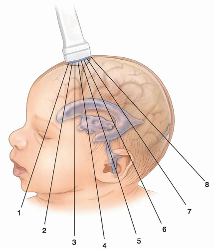 FIGURE 21-1 Coronal scan planes (1 to 8). Coronal imaging planes via the anterior fontanelle approach. |
Ventricles
The purpose of the ventricular system is to provide a pathway for the circulation of CSF. The ventricular system is composed of four ventricles: the paired lateral ventricles and the midline third and fourth ventricles. The paired lateral ventricles are the largest of the ventricles and are located on either side within the cerebrum of the brain. They are divided into four segments: the frontal (anterior) horn, body, temporal, and occipital (posterior) horn. The trigone (atrium) of the lateral ventricle is the region where the anterior, occipital, and temporal horns converge.
The paired lateral ventricles drain into the third ventricle through the foramen of Monro and the third ventricle drains into the fourth through the aqueduct of Sylvius. The fourth ventricle drains into the subarachnoid space through the foramina of Luschka and Magendie and then into the basal cistern. CSF flows upward around the brain to the vertex, where it is resorbed by the arachnoid granulations into the superior sinuses. CSF also flows around and down the spinal subarachnoid space.3
Choroid Plexus
The CP is responsible for the production and regulation of CSF. The largest part of the CP, which is known as the glomus, is seen as an echogenic structure within the lateral ventricles at the level of the trigone. It tapers as it courses anteriorly and ends at the caudothalamic groove. The CP never extends anterior to the foramen of Monro into the frontal horns or posteriorly into the occipital horns. CP is also present in the roof of the third and fourth ventricles.
Corpus Callosum
The two sides of the cerebrum are joined by the corpus callosum. The corpus callosum is the largest white matter structure in the brain and contains nerve tracts that allow communication between the right and left hemispheres of the brain. It is divided into the rostrum, genu, body, and splenium (posterior part) and forms the roof of the lateral and third ventricle.
Caudate Nucleus
Located in each hemisphere of the brain, the caudate nucleus is the most medial of the four basal ganglia. It is an elongated, curved mass of gray matter, and it consists of head, body, and tail. The head and body form part of the floor of the anterior horn of the lateral ventricle, and the tail curves back toward the anterior, forming the roof of the inferior horn of the lateral ventricle.
Thalamus
The thalami are paired structures of gray matter situated between the cerebral cortex and the midbrain. They are
located in the center of the brain, one beneath each cerebral hemisphere, next to the third ventricle. The thalami can be thought of as relay stations for nerve impulses carrying sensory information into the cerebral cortex.
located in the center of the brain, one beneath each cerebral hemisphere, next to the third ventricle. The thalami can be thought of as relay stations for nerve impulses carrying sensory information into the cerebral cortex.
Fissures
There are five major fissures that divide the cerebral hemispheres: interhemispheric fissure, Sylvian fissure, parieto-occipital fissure, transverse fissure, and central fissure. The interhemispheric fissure (also known as the falx or longitudinal fissure) divides the cerebrum into right and left hemispheres. The Sylvian fissure (also known as lateral fissure) divides the frontal and parietal lobes from the temporal lobe. The parieto-occipital fissure separates the occipital lobe from the parietal lobe. The transverse fissure separates the cerebrum from the cerebellum. The central fissure (also known as fissure of Rolando) separates the frontal and parietal lobes.
Cisterna Magna
The cisterna magna (CM) is a fluid-filled structure that communicates with the fourth ventricle. It lies between the cerebellum and the dorsal surface of the medulla.
SCANNING PROTOCOL
Neurosonography should be performed in a standardized manner with a specific sequence of images and key anatomical structures identified on each scan. Most premature infants will have serial scans over the course of their hospital stay, and a standard approach will ensure that consistency be maintained from examiner to examiner. The examiner should also know the approximate gestational age of the infant. This will aid in differentiating age-related features from pathology.
Coronal Scanning Protocol
Scanning in the coronal plane via the anterior fontanelle should minimally include six to eight images. Magnified image planes should be incorporated to draw attention to suspicious areas or to enhance the visualization of abnormal areas. Maintaining side-to-side symmetry while scanning in the coronal plane is a technique that will require some practice; however, doing so is essential to obtaining a good study. Representative coronal sections are obtained by systematically angling the transducer from the frontal lobe of the infant brain to the occipital cortex, anterior to the orbital ridge, past the occipital lobes. The scanning planes are depicted in Figure 21-1. In the coronal plane, by convention, image labeling should have the right side of the brain projected on the left side of the image.
The most anterior coronal image is obtained through the frontal lobes of the cerebral cortex at the level of the orbital ridge and the interhemispheric fissure (Fig. 21-2). This scan is anterior to the frontal horns. The next scan should include the triangular-shaped, fluid-filled frontal horns and the head of the caudate nuclei adjacent to the lateral walls of the ventricles. The fluid-filled cavum septi pellucidi can be seen between the frontal horns of the lateral ventricles. Anterior to the cavum is the corpus callosum (Fig. 21-3). The next scan is slightly more posterior and is obtained at the level of the foramen of Monro. This is where the lateral ventricles and the third ventricle communicate. The normal slit-like third ventricle is often difficult to visualize owing to volume averaging; its transverse diameter often falls within the beam width. Slight off-axis angulation will offset the
beam thickness effect and will often allow visualization of the normal third ventricle. When dilated, it can be imaged quite easily. Continuing with further posterior angulation, the echogenic CP can be seen in the floor of the lateral ventricle and in the roof of the third ventricle. This scan is slightly posterior to the third ventricle. The echogenic V-shaped tentorium can be seen in this scan anterior to the cerebellum. Posterior to the vermis of the cerebellum is the CM. The Y-shaped Sylvian fissure can also be seen in this plane (Fig. 21-4). With more posterior angulation, the next scan demonstrates the echogenic star-shaped quadrigeminal cistern posterior to the thalami. Posterior to the tentorium is the posterior fossa containing the echogenic cerebellum (Fig. 21-5).
beam thickness effect and will often allow visualization of the normal third ventricle. When dilated, it can be imaged quite easily. Continuing with further posterior angulation, the echogenic CP can be seen in the floor of the lateral ventricle and in the roof of the third ventricle. This scan is slightly posterior to the third ventricle. The echogenic V-shaped tentorium can be seen in this scan anterior to the cerebellum. Posterior to the vermis of the cerebellum is the CM. The Y-shaped Sylvian fissure can also be seen in this plane (Fig. 21-4). With more posterior angulation, the next scan demonstrates the echogenic star-shaped quadrigeminal cistern posterior to the thalami. Posterior to the tentorium is the posterior fossa containing the echogenic cerebellum (Fig. 21-5).
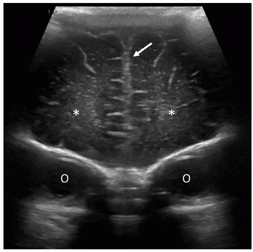 FIGURE 21-2 Frontal lobes. Coronal image at the level of the frontal lobes shows the interhemispheric fissure (arrow), normal echogenicity of the frontal lobes (asterisks), and orbital ridges (O). This image is anterior to the frontal horns and lateral ventricles. |
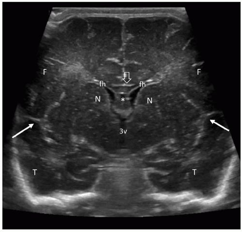 FIGURE 21-3 Frontal horns. In this coronal image, the frontal horns (fh) appear as triangular-shaped, fluid-filled spaces separated by the cavum septi pellucidi (asterisk). The head of the caudate nuclei (N) lie adjacent to the lateral walls of the ventricles. The hypoechoic corpus callosum (cc) forms the roof of the cavum. The third ventricle (3v) can also be seen. The echogenic Y-shaped Sylvian fissures (arrows) are seen laterally. F, frontal lobe; T, temporal lobe. |
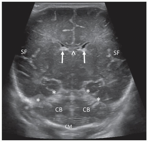 FIGURE 21-4 Coronal view posterior to the third ventricle. The echogenic CP is seen in the floor of the lateral ventricle (arrows) and the roof of the third ventricle (caret). The Y-shaped Sylvian fissures (SF) are seen laterally. Also visible are the echogenic tentorium (asterisks), the cerebellar hemispheres (CB), and the cisterna magna (CM). |
Angling slightly more posterior, the trigones of the lateral ventricles dominate this section. The glomi of the CP fill most of the lateral ventricles at this level. The periventricular parenchyma lateral to the ventricles should be evaluated carefully. These areas represent the periventricular white matter, and the echogenicity of this area should not be brighter than the CP (see the section on Prominent Periventricular Blush). A benefit of the coronal plane is that it allows contralateral comparison of the echogenicity between the CP and the periventricular parenchyma. Increased echogenicity of this area should arouse suspicion for hemorrhage/infarction and requires follow-up evaluation (Fig. 21-6). The final and most posterior scan predominantly visualizes the gyri and sulci of the occipital lobe, the periventricular white matter, and the posterior interhemispheric fissure (Fig. 21-7).3
Sagittal/Parasagittal Scanning Protocol
The transducer is rotated 90 degrees from the coronal plane and, starting at the midline, is angled medial to lateral sequentially through each cerebral hemisphere via the anterior fontanelle. The scanning planes are depicted in Figure 21-8. Image labeling, by convention, places the anterior aspect of the brain on the left side of the image. The midline, right side, and left side need to be annotated, respectively. In the midline, the crescentic hypoechoic corpus callosum is visualized just above the cavum septum pellucidum and vergae (seen in premature infants only). Superiorly, the corpus callosum is surrounded by the hyperechoic pericallosal
sulci, which contains the pericallosal artery. The vascular pulsations from these vessels can be appreciated on real-time imaging. Inferior to the corpus callosum is the third ventricle. Anterior to the echogenic vermis of the cerebellum is the triangular-shaped fourth ventricle. The moderately echogenic midbrain is anterior to the fourth ventricle, and the echogenic cerebellar vermis is posterior to the fourth ventricle (Fig. 21-9). The CM is seen inferior to the vermis and should always be visualized. Absence of the CM is indicative of pathology. Parasagittal images are obtained by angling the transducer from the midline through the right and left cerebral hemispheres from medial to lateral (or lateral to medial). The main anatomic landmark in the next image is the caudothalamic groove. The anterior extent of the CP tapers to a point into this groove, which is formed by the head of the caudate nucleus anteriorly and the thalamus posteriorly. The head of the caudate nucleus is slightly more echogenic than the thalamus. In the premature neonate, the fragile germinal matrix (GM) is located in these areas and is a common site for hemorrhage (see further discussion under the section on Intracranial Hemorrhage). This is an area where a magnified image plane is recommended (Fig. 21-10). With continued angulation laterally, the next image is through the lateral ventricle. The frontal horn of the lateral ventricle is more medial than the occipital horn; thus, to visualize the entire ventricle, the anterior part of the transducer needs to be angled obliquely with the front end of the transducer angled medially and the posterior part angled slightly more lateral. This parasagittal section will visualize a good portion of the frontal horn and body of the lateral ventricle. The thalamus is seen inferior to the head of the caudate nucleus, and the CP should taper into the caudothalamic groove (Fig. 21-11). Angling more laterally, the highly echogenic glomus of the CP is seen filling the trigone of the lateral ventricle and has a comma-shaped configuration because it courses posterior toward the temporal horn (Fig. 21-12). There should be no CP extending anterior to the third ventricle or into the occipital horn. Several images may be needed to image the complete ventricular system. The temporal horn or occipital horn will need to be imaged separately because it is not always possible to
line up the entire ventricular system in one plane. In a nondilated ventricular system, the temporal and occipital horn may be difficult to visualize. As on the coronal section, the periventricular white matter lateral and posterior to the trigones of the lateral ventricles requires careful evaluation. This area should not be brighter than the CP. Angling more lateral to the ventricle, the next scan demonstrates the far lateral periventricular white matter tracts and the echogenic Sylvian fissure. On real-time scanning, the middle cerebral artery (MCA) branches can be seen pulsating within this fissure (Fig. 21-13).3
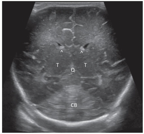 FIGURE 21-5 Quadrigeminal cistern. Coronal image taken at the level of the quadrigeminal cistern. The star-shaped echogenic quadrigeminal cistern (Q) is seen inferior to the thalami (T). The cerebellum (CB) and the echogenic choroid plexus (CP, carets) in the floor of the lateral ventricles are also visualized. |
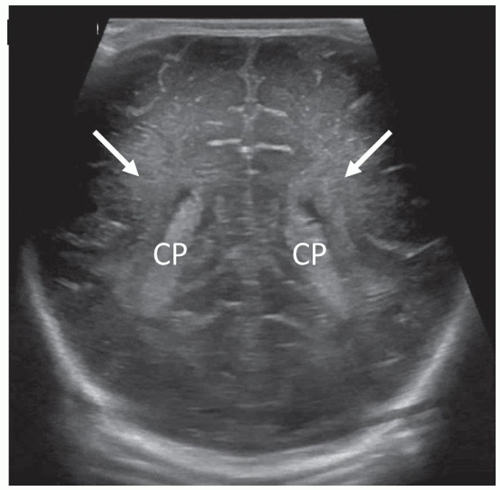 FIGURE 21-6 Choroid plexus (CP). Coronal scan at the level of the trigones of the lateral ventricles. The largest part of the CP can be seen occupying most of the lateral ventricles. The periventricular white matter (also known as the optic radiation) is located lateral to the ventricles (arrows). |
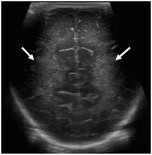 FIGURE 21-7 Occipital lobes. Coronal image taken posterior to the occipital horns of lateral ventricles shows the normal echogenic periventricular white matter (arrows) and the occipital cortex. |
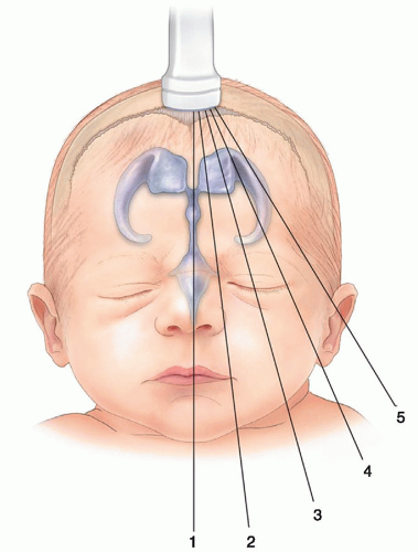 FIGURE 21-8 Sagittal scan planes. Sagittal/parasagittal imaging planes via the anterior fontanelle approach. |
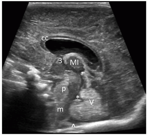 FIGURE 21-9 Sagittal midline. Normal midline sagittal image on a term infant. The hypoechoic corpus callosum (CC) is seen anterior to the cavum septum pellucidum. The third (3) and fourth (*) ventricles are visible in this plane. Posterior to the fourth ventricle is the echogenic vermis of the cerebellum (V) and the cisterna magna (CM, caret). Anterior to the fourth ventricle is the pons (p) and medulla (m). MI, massa intermedia. |
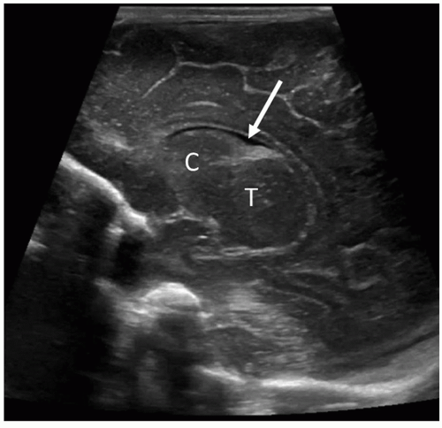 FIGURE 21-10 Caudothalamic groove. Parasagittal scan at the level of the caudothalamic groove. Head of the caudate nucleus (C) is seen anterior to the thalamus (T). Between these two structures is the caudothalamic groove or notch (arrow), which contains the anterior extent of the choroid plexus (CP). |
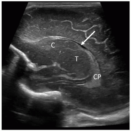 FIGURE 21-11 Lateral ventricle. Parasagittal through the lateral ventricle. The highly echogenic choroid plexus (CP) is seen within the body of the lateral ventricle and tapers at the caudothalamic groove (arrow). The caudate nucleus (C), anterior to the thalamus (T) is again noted. This is the location of the germinal matrix (GM) in premature infants. |
 FIGURE 21-12 Parasagittal choroid plexus. Parasagittal scan through the body (B) of the lateral ventricle. The echogenic choroid plexus (CP) is seen within the trigone of the ventricle. FH, frontal horn; OH, occipital horn; TH, temporal horn. |
Supplemental Views
Supplemental windows exist to augment the diagnostic accuracy of the neurosonogram. These alternative acoustic windows allow improved access to visualize and detect pathologic
conditions and structural malformations in the brainstem, cerebellum, and subarachnoid cisterns. The PF provides an enhanced view of the glomus of the CP, its extension into the body and temporal horn of the ventricle. It allows better visualization of the occipital horn, facilitating the detection of intraventricular blood clot from normal structures, like the calcar avis (Fig. 21-14). The MF depicts a superior view of the cerebral peduncles, thalamus, quadrigeminal cistern, cerebellar hemispheres, vermis, and the CM by avoiding the echogenic tentorium (Fig 21-15).
conditions and structural malformations in the brainstem, cerebellum, and subarachnoid cisterns. The PF provides an enhanced view of the glomus of the CP, its extension into the body and temporal horn of the ventricle. It allows better visualization of the occipital horn, facilitating the detection of intraventricular blood clot from normal structures, like the calcar avis (Fig. 21-14). The MF depicts a superior view of the cerebral peduncles, thalamus, quadrigeminal cistern, cerebellar hemispheres, vermis, and the CM by avoiding the echogenic tentorium (Fig 21-15).
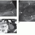
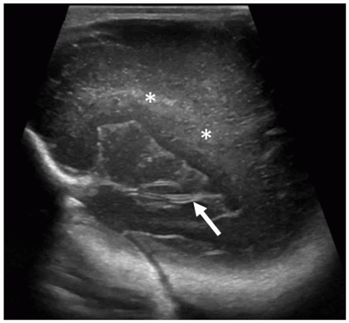 FIGURE 21-13 Sylvian fissure (lateral fissure). Parasagittal scan lateral to the ventricle. The Sylvian fissure (arrow) is seen in this image. Pulsations from branches of the middle cerebral artery (MCA) can be seen on real-time scanning. Normal periventricular white matter (asterisks) lateral to the ventricle. |
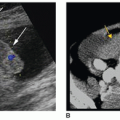
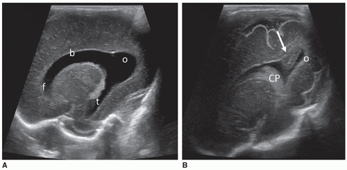 FIGURE 21-14 Posterior fontanelle (PF). A: Image taken from the PF demonstrates the ventricular system. Frontal horn (f), body (b), temporal horn (t), and occipital horn (o). Compare the occipital horn in images (A) and (B). B: Note the presence of hypoechoic tissue with a central echogenic sulcus projecting into the medial wall of the occipital horn. This is the calcar avis (arrow). Doppler imaging is useful to differentiate between normal anatomy and hemorrhage. CP, choroid plexus. |
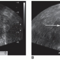
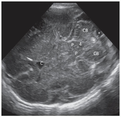 FIGURE 21-15 Posterior fossa. Normal posterior fossa structures obtained via the mastoid fontanelle (MF), depicting a normal fourth ventricle (4), cerebellar hemispheres (CBs), midline vermis (v), cisterna magna (CM, *), cavum (C), cerebral peduncles (P). |
Spectral and Color Doppler Imaging of the Brain
Valuable cerebrovascular hemodynamic information can be gained by adding color, B-flow, power, and spectral Doppler imaging to the exam. Duplex imaging allows the assessment of intracranial anatomy (Fig. 21-16), the patency of arterial and venous structures (Fig. 21-17), blood flow dynamics, and velocity measurements.4 This is critical when establishing a diagnosis such as increased
intracranial pressure, asphyxia, brain injury, and brain death. Doppler may be performed through the anterior fontanelle or transtemporal, through the sphenoid fontanelle (Fig. 21-18). Placing probe 1 cm anterior and superior to the tragus of the ear enables access to the circle of Willis, a ring of vessels that sit at the base of the brain. It is formed anteriorly by the internal cerebral artery (ICA) as it terminates into the MCA, anterior cerebral artery (ACA), and posterior communicating artery (Fig. 21-19) and joins with the vertebrobasilar system, composed of the vertebral and basilar arteries. The role of the circle of Willis is to supply collateral circulation and decrease blood pressure, through pressure equilibrium, in the brain. The MCA provides approximately 80% of blood to the cerebral hemispheres. The ACA and pericallosal artery are well seen through the anterior fontanelle, whereas the MCA is best evaluated from the transtemporal acoustic window (owing to the parallel angle of insonation). The resistive index (RI) (defined as PSV – EDV / PSV) is influenced by several factors, including peripheral vascular resistance, blood volume, and flow velocity. An increase in diastole will result in a decreased RI, whereas a decrease in diastole will result in an increased RI. Resistive indices decrease from full-term to preterm neonates owing to the maturation of cerebrovascular autoregulation (Table 21-1). Larger cerebral arterial vessels typically yield values between 0.71 and 0.80 in most neonates; resistive indices may also be influenced by a variety of conditions related to hemodynamics (Table 21-2).2
Venous drainage of the brain can be assessed by imaging the veins and dural venous sinuses. Superficial veins empty into the SSS and lie on the surface of the cerebral hemispheres. Deep veins, including the internal cerebral vein and vein of Galen (VoG), drain into the straight sinus. Optimization of the Doppler technique is key in obtaining diagnostic information.
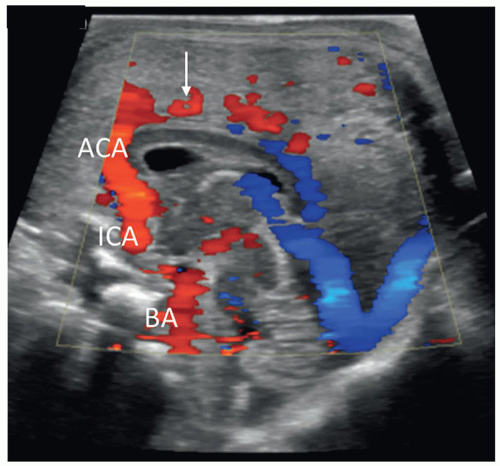 FIGURE 21-16 Color Doppler. Normal sagittal color flow midline image depicting the anterior cerebral artery (ACA), internal carotid artery (ICA), basilar artery (BA), and pericallosal artery (arrow) as it courses over the corpus callosum. |
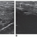
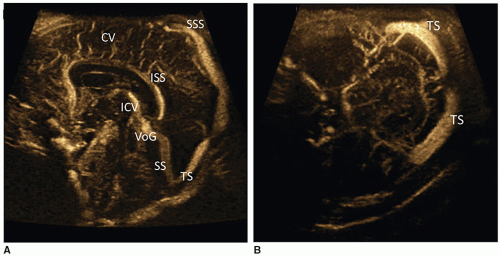 FIGURE 21-17 A: B-flow image of veins and (B) dural venous sinuses. The dural sinuses drain venous blood via the internal jugular vein. The superior sagittal sinus (SSS) also assists with the production of cerebrospinal fluid (CSF). CVs, cortical veins; EDV, end diastolic velocity; ICV, internal cerebral vein; ISS, inferior sagittal sinus; PSV, peak systolic velocity; SS, straight sinus; TS, transverse sinus; VoG, vein of Galen. |
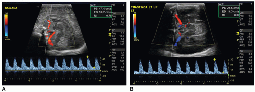 FIGURE 21-18 Normal arterial spectral Doppler flow pattern of the anterior cerebral artery (ACA) (A) and middle cerebral artery (MCA) (B). |
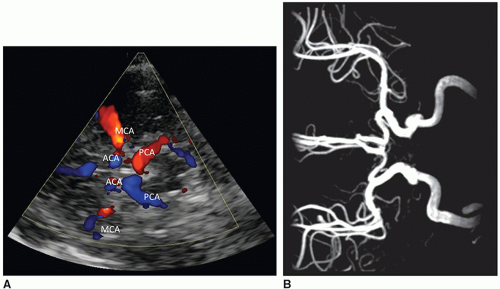 FIGURE 21-19 Transtemporal view of the circle of Willis. A: Anterior cerebral artery (ACA—A1 segment), middle cerebral artery (MCA—M1 segment), posterior cerebral artery (PCA). B: MR (Magnetic Resonance) angiogram depicting the circle of Willis. |
TABLE 21-1 Normal Arterial Doppler Hemodynamics in the Newborn (ACA) | ||||||||||
|---|---|---|---|---|---|---|---|---|---|---|
| ||||||||||
TABLE 21-2 Conditions that Influence the Resistive Index | ||||||||||||||
|---|---|---|---|---|---|---|---|---|---|---|---|---|---|---|
| ||||||||||||||
Three-Dimensional Sonography
Three-dimensional (3D) sonography has gained acceptance as a component of clinical imaging. Although the early applications of 3D sonography focused on obstetrical, gynecologic, and cardiac applications, this technique is showing promise as an emerging technique in imaging the brain.5,28 Recent advances in computer technology and improvements in reconstruction software and transducer technology have driven the expansion. 3D imaging capabilities are available on most sonography systems.
Some of the advantages of 3D over two-dimensional (2D) scanning are a decrease in the examination time, less variability among operators, and the capability of viewing anatomy and pathology in an infinite number of scanning planes unattainable through 2D scanning. 3D sonography also provides additional benefits for education and training because the data can be virtually rescanned and manipulated at a workstation long after the exam is completed. A typical 2D neonatal head scan takes approximately 10 to 15 minutes to perform. The time needed for 3D image acquisition is only a few minutes. Rapid acquisition of data reduces the duration of stimulation to the infant and may have the potential of reducing some musculoskeletal injuries suffered by sonographers. The digital data sets are saved and recalled for reconstruction and interpretation at an offline computer. Recent advances in volumetric sonography have enabled the volumetric data to be viewed in tomographic slices (Fig. 21-20) and in multiplanar mode (Fig. 21-21), in which the reconstructed axial plane is comparable to other modalities like computed tomography (CT) and magnetic resonance imaging (MRI). With this technique, a volumetric transducer sweeps through the brain acquiring a volume of images. After capturing the volume data set, the images are sliced into axial, coronal, and sagittal planes.4
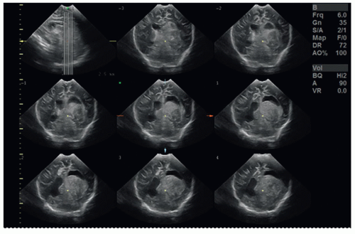 FIGURE 21-20 Tomographic ultrasound imaging (TUI). TUI demonstrates large parenchymal hemorrhage in an ex 24-week infant with ventriculoperitoneal (VP) shunt failure. |
NORMAL VARIANTS
Sonographic Features of the Mature versus Immature Brain
Sonographically, certain features are markers of prematurity and should not be misinterpreted as abnormal. The premature brain changes significantly in appearance from 26 weeks until term, including development of sulci. Knowing the approximate gestational age of the infant will aid in differentiating age-related features from pathology.
Cavum Septi Pellucidi, Cavum Vergae, and Cavum Veli Interpositi
The cavum septi pellucidi is a CSF-filled space lying between the frontal horns of the lateral ventricles. In very premature infants, a posterior extension of the cavum septi pellucidum, called the cavum vergae, is often seen. On the coronal scan, it can be seen lying between the bodies of the lateral ventricles, and on the midline sagittal scan, it can be seen posterior to the corpus callosum (Fig. 21-22). Closure of this space starts at approximately 6 months of gestation and progresses from the posterior to the anterior. The cavum veli interpositi (Fig. 21-23) is another subcallosal CSF-filled cavity that must be differentiated from a VoG aneurysm. In late-gestation infants, only the anterior cavum septum pellucidum may be appreciated. This fetal structure typically closes by 3 to 6 months after birth, but it may remain open into adulthood in approximately 15% of patients.
Related posts:

Stay updated, free articles. Join our Telegram channel

Full access? Get Clinical Tree


