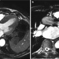
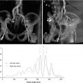
Fig. 5.1
Computed tomographic angiography reveals significant left subclavian artery (LSA) tortuosity as it traverses the thoracic inlet, making it more prone to injury for a retrograde subclavian/transaxillary approach. In addition, a left internal mammary artery (LIMA) bypass graft to the left anterior descending artery is present
Antegrade Transapical Approach
The transapical approach to TAVR is performed via a left anterolateral mini-thoracotomy between the fifth and sixth intercostal space under general anesthesia [32]. The incision site is determined by palpation, fluoroscopy, transthoracic echocardiography, and/or multidetector computed tomography (CT). Transapical access is achieved by placing two purse-string, pledgeted sutures within the apical myocardium and introducing the delivery sheath into the left ventricle.
Apical complications are less than 1 % in experienced centers [33, 34]. The avoidance of traversing the aortic arch potentially reduces liberation of cerebral emboli. The short distance from the LV apex to aortic valve allows for improved operator maneuverability and control during valve deployment. Patients with an intended more ventricular valve positioning, such as in patients with low implanted coronary arteries, a prior mitral prosthesis, or mild septal hypertrophy that is not a contraindication for TAVR, may be easier to achieve when delivery forces can be directed toward the apex [35].
The major downsides of transapical approach are the concerns for apical bleeding, pseudoaneurysm, or apical scar, especially in patients with left ventricular dysfunction [36]. Cardiac muscle of the elderly, high-risk, frail patient can be friable, a quality not typically identifiable on CT. In addition, further pulmonary impairment with patients having underlying lung disease may be a consequence of the thoracotomy. Current data suggests faster recovery times after transapical TAVR, with early and late morbidity and mortality comparable with that of minimally invasive SAVR [37] [38].
Retrograde Transaortic TAVR Approach
The transaortic or direct aortic approach to TAVR is performed through a mini-sternotomy or right mini-thoracotomy through the second intercostal space, with dissection of the underlying tissue to expose the ascending aorta [39, 40]. For mini-sternotomy, a small supraclavicular counter incision is made with a tunnel created to the sternotomy site in order to secure sheath placement and orient the line of delivery to the aortic valve. A mini-sternotomy provides excellent exposure to all aortic orientations.
The first series of patients to undergo direct aortic approach TAVR were poor candidates for transfemoral and transapical approaches due to severe pulmonary impairment or marked chest wall deformities, suggesting a population well suited for this approach [40]. Delivery avoiding the aortic arch may also potentially reduce a source of cerebral emboli. With the avoidance of thoracic wall trauma and subsequent postoperative pain, which may occur with the transapical approach, there may be less impairment in respiratory function. Nonetheless, reported procedural outcomes between transapical and direct aortic approaches are similar [40].
The Complex Aortic Stenosis Patient
In addition to the multitude of medical comorbidities, technical difficulties arise which can make SAVR a challenge. These challenges include heavily calcified and/or atheromatous ascending aorta such as a porcelain aorta, prior CABG surgery with patent bypass grafts that can be damaged during sternotomy or dissection, and multiple redo surgeries with extensive scar tissue or sequelae of chest and/or mediastinal radiation (Fig. 5.2). Calcification of the ascending aorta is commonly present in the elderly surgical population. Traditional options have been ascending aortic replacement and/or endarterectomy under circulatory arrest with subsequent cross-clamping and cardiopulmonary bypass and apical-descending aortic conduits, all adding significant risk to the patient.
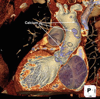

Fig. 5.2
3D volume-rendered computed tomographic images can be performed of the aorta. Using the cut-plane function, portions of the aortic root and ascending aorta are virtually removed to reveal extensive calcific atherosclerotic disease
Furthermore, similar technical difficulties arise that can make TAVR a challenge. Heavy peripheral arterial calcification, atherosclerosis, tortuosity, and smaller-caliber arterial vasculature can make access and delivery system advancement difficult and dangerous [4]. Ulcerative plaque and mobile atheroma within the aortic arch and great vessel increase the potential risk of dislodgement during catheter manipulation and subsequent embolization. Significant proximal septal bulging, particularly in patients with left ventricular outflow tract obstruction, and a prior mitral valve prosthesis may prevent adequate positioning at risk for transcatheter valve embolization into the aorta. Myomectomy during SAVR can address septal hypertrophy, but this is not the case for TAVR.
In addition, bulky aortic leaflet calcification may increase the risk of coronary occlusion and paravalvular regurgitation [41, 42]. Displacement of leaflet edge calcification into the aortic root space may obstruct the coronary ostium in patients with a low ostial height. Calcification within the device-landing zone may resist deployment of a transcatheter prosthesis, causing a gap between the prosthesis and the native valve. An Agatston calcium valve score above 3,000 may portend an increased risk for relevant paravalvular regurgitation [43]. Overall, addressing the risks and benefits of SAVR or TAVR in the complex patient requires multimodality imaging with a multidisciplinary analysis and discussion.
Multimodality Imaging in Aortic Stenosis
TAVR, like minimally invasive SAVR, lacks the direct visualization provided by a conventional open, SAVR procedure. Multimodality imaging for preprocedural assessment and for guidance within the hybrid laboratory offers an alternative means of visualization to achieve important information for valve implantation. More advanced imaging such as 3D transesophageal echocardiography (TEE), MDCT, and, more recently, CTA-fluoroscopy or rotational angiography-fluoroscopy fusion imaging is becoming essential for AS management.
In SAVR, conventional selective angiography is the standard diagnostic tool for anatomic evaluation of native coronary arteries and bypass grafts. However, it neither provides the surgeon with complete information on the proximity of the aorta, the right ventricle, coronary arteries, and grafts to the sternum nor the extent of aortic disease. CT with 3D volume rendering is able to show the relationship of these structures to one another with cut-plane able to virtually remove structures in order to visualize underlying anatomy [44] (Fig. 5.3). Median sternotomy in the setting of an adherent right ventricle, bypass grafts, or innominate vein can lead to catastrophic bleeding or myocardial injury.
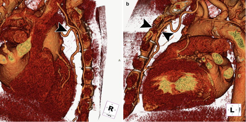

Fig. 5.3
3D cardiac reconstruction using volume-rendering techniques shows the relationship of the aorta, right ventricle, coronary arteries, and bypass grafts in relation to the sternum. In the right lateral (a) and left lateral (b) orientations, the left internal mammary artery bypass graft (black arrowhead) is visualized adherent to the posterior sternum
Curved multiplanar reconstructions can be performed of the aorta to identify aortic calcification and atherosclerosis and the location of bypass grafts, all in relation to the aortic valve. In addition to surveying the substernal, mediastinal, and cardiac anatomy for abnormalities, CT also aids in preoperative decision analysis and cannulation strategies. It is more commonly performed prior to isolated valve procedures and has been showed to markedly reduce postoperative stroke rates, with the selection of cannulation site and clamping strategy largely influenced by CT [27, 44]. Occasionally, TEE, along with 3D full-volume mode images, can reveal advanced atherosclerosis with mobile and pedunculated atheroma (Fig. 5.4).
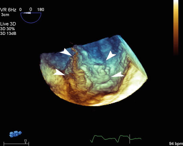

Fig. 5.4
3D transesophageal echocardiography with full-volume mode reveals advanced atherosclerosis with large, mobile atheroma with the edges identified (white arrowheads)
Regardless of the fact that conventional surgical approach allows for intraprocedural sizing of the prosthesis, an accurate preoperative assessment can improve procedure and prosthesis selection. The role of multimodality imaging in choosing the prosthesis as well as implantation technique becomes widely recognized as valuable for TAVR. Multimodality imaging, in particular CT and TEE, allows for accurate estimation of prosthesis size [45]. Accurate preoperative valve sizing may help to avoid postoperative patient-prosthesis mismatch for patients at high risk. This can also allow for optimal selection of implantation technique: supra-annular versus intra-annular, the need for aortic root enlargement, and stented versus stentless or mechanical prostheses.
In TAVR, CT provides a comprehensive assessment of the iliofemoral arteries, thoracoabdominal aorta, ascending aorta, aortic root, and aortic annulus (Fig. 5.5). Atherosclerotic burden, degree of calcification, and tortuosity can be easily determined for safety of vascular access and delivery [4]. Measurements of the ascending aorta can assess the ability for successful implantation of self-expanding valves and of the aortic root to assess for the potential for coronary occlusion. Analysis and measurements of annular size and shape are crucial for appropriate prosthesis sizing. Furthermore, quantification and localization of leaflet/annular calcification is possible, but its role in conduction system abnormalities, coronary obstruction, paravalvular regurgitation, and cerebrovascular events and the ability to modify TAVR techniques to reduce complications are developing.
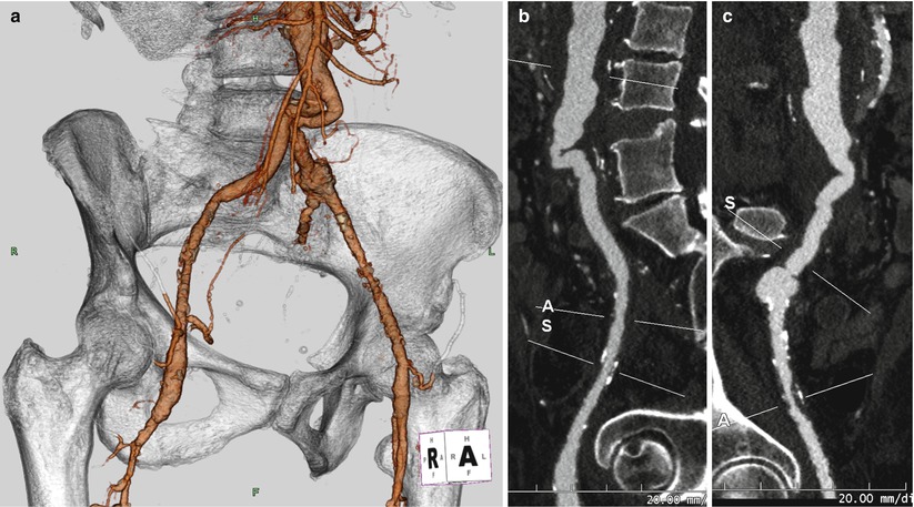

Fig. 5.5
(a) Computed tomographic angiography (CTA) with 3D volume rendering of the aortic bifurcation and iliofemoral system reveals tortuosity of the bilateral aortoiliac junction. Curved multiplanar reconstruction (MPR) of the right (b) and left (c) iliofemoral system shows the acute angle at the aortoiliac junction and evidence of calcific and non-calcific disease of the bilateral iliac arteries (A and S identify the axial cut-planes perpendicular to the centerline that can be moved along the vasculature, used to determine luminal dimensions)
Real-time 3D TEE is also an important modality for preprocedural and intraprocedural assessment of TAVR. Similar to CT, precise assessment of the aortic root and annulus can be made, potentially reducing the chance of sizing error [4]. 3D visualization allows for improved positioning of transcatheter valve and determination of implantation depth during valve deployment. In addition, 3D TEE can help to evaluate the extent of and precise location of the aortic regurgitation jet following valve implantation (Fig. 5.6). In SAVR, improved localization of a paravalvular leak together with defect dimensions can assist in procedural management and need for immediate revision.
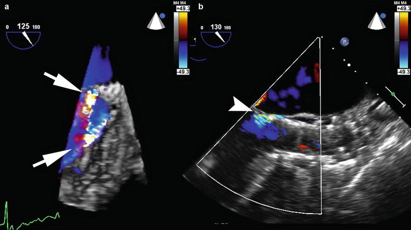

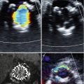
Fig. 5.6
(a) 3D full-volume transesophageal echocardiography with color Doppler reveals two jets of aortic paravalvular regurgitation (white arrows) around a self-expanding CoreValve prosthesis (Medtronic, Minneapolis MN). (b) 2D long-axis view of the aorta after CoreValve valve-in-valve (ViV) implantation demonstrates mild residual paravalvular regurgitation (white arrowhead)
Fusion imaging is playing an increasing role in TAVR [46, 47]. It provides the ability to merge the 3D data of important cardiac and surrounding structures from either CT angiography or rotational angiography with live 2D fluoroscopy, while preserving the spatial and temporal resolution of fluoroscopy. The fundamentals of fusion imaging are described in a later chapter. There are predominately two proprietary softwares available that employ fuse CT or rotational angiography with fluoroscopy: HeartNavigator (Philips Healthcare, Best Netherlands) and syngo DynaCT (Siemens Medical, Berlin Germany). Syngo DynaCT utilizes intraprocedural rotational angiography images, reducing variables that can alter cardiac anatomy compared to a preprocedural CT angiography. Nevertheless, the primary utility of fusion imaging in TAVR includes the localization of aortic valve anatomy, determination of valve size, identification of optimal c-arm positioning, and guidance for valve deployment.
The role of fusion imaging in hybrid approaches to TAVR remains undefined but has been utilized for the retrograde transaortic and antegrade transapical approaches (Fig. 5.7). The optimal position for direct aortic cannulation can be determined based on preprocedural CT angiography images. A site is selected that is away from atherosclerotic plaque and is a sufficient distance from the aortic annulus to allow for transcatheter deployment while still maintaining sheath access. In addition, maintaining an entry site away from bypass grafts if present and providing the correct orientation for deployment is equally important.
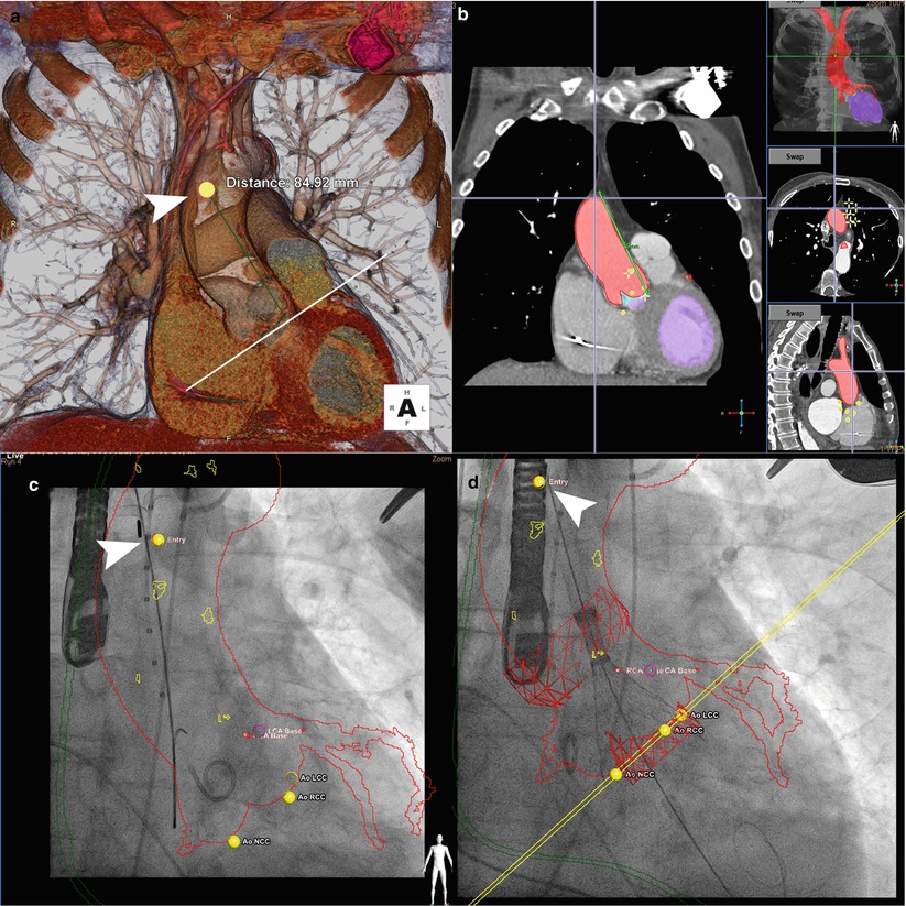

Fig. 5.7
Fusion imaging for retrograde transaortic approach. (a) Preprocedural computed tomographic angiography (CTA) with 3D cardiac reconstruction is used to identify an optimal position (arrowhead, yellow dot) for direct aortic cannulation, away from atherosclerotic plaque and with sufficient distance from the aortic annulus (>6 cm recommended for CoreValve implantation). (b) Segmentation of volume-rendered images identifies the aorta along with the coronary arteries and bypass grafts (red) and left ventricle (purple) on sagittal, axial, and coronal views. (c) Registration is performed to match the position and scale of the overlayed CTA onto fluoroscopy. The aorta and coronary arteries (red outline), nadir of coronary cusps and direct aortic access and tip of the delivery sheath (arrowhead) are visualized. (d) Deployment of the CoreValve is visualized at one third deployment (CoreValve Medtronic, Minneapolis MN; HeartNavigator Philips Healthcare, Best Netherlands)
A landmark can be placed at this site and CT angiography and fluoroscopy images co-registered such that the landmark moves with the c-arm and can guide transaortic entry. Also, an outline of the right internal mammary artery overlayed onto fluoroscopy can guide incision such that the medial edge of right anterior thoracotomy incision is 1.5–2 cm lateral to the sternal edge. For the antegrade transapical approach, preprocedural CT angiography and fusion imaging can help identify transapical access site both on the skin and on the left ventricle, determining the shortest trajectory of entry that is in direct line with the aortic valve.
The Burden of Paravalvular Regurgitation
Paravalvular leak is a serious complication associated with SAVR. Paravalvular leaks occur in 2–10 % of the surgical implants in the aortic position with 1–5 % having clinical symptoms of congestive heart failure and/or hemolysis [48, 49]. A result of incomplete seal between the sewing ring and annulus, paravalvular leaks can occur early due to technical aspects of surgery or later due to suture dehiscence or gradual resorption of incompletely debrided annular calcification.
The same problem of paravalvular regurgitation that has burdened SAVR also occurs with TAVR. It is generally caused by inadequate expansion of the prosthesis from either underinflation or calcification. It can also occur with incorrectly sized prostheses or improper positioning. Nearly one-third of patients have paravalvular regurgitation that is more than mild. Although the incidence of residual mild or moderate paravalvular regurgitation is significantly higher in TAVR compared to SAVR, moderate-severe and severe postprocedural regurgitation is rare [17]. Nonetheless, even mild paravalvular regurgitation is associated with increased late mortality [17].
Surgical correction of paravalvular leak related to surgical prosthesis involves either repair of the leak by direct suturing, patch closure, or autologous tissue incorporation or re-replacement of the valve. Transcatheter techniques have been adapted to paravalvular leak closure with reasonable success [50]. For transcatheter prostheses, acute techniques of balloon post-dilatation, valve-in-valve implantation, or valve repositioning, depending on the prosthesis type and the mechanism, can be employed. Percutaneous paravalvular closure of a transcatheter prosthesis has been performed 3–6 months after TAVR to allow for endothelialization and stabilization, but further evaluation is warranted [51].
Multidisciplinary Team Approach
Analyzing the risk of conventional SAVR is clearly more complicated in extreme and high-risk patients. Preoperative risk stratification models such as the Society of Thoracic Surgeons and the EuroSCORE may be useful to stratify potential candidates by providing a quantitative assessment [52]. However, AS patients are a very heterogeneous group with varying life expectancies, comorbidities, and functional status. Current scores have not been designed to evaluate this population and do not capture all of the relevant variables [53].
The limitations of scoring systems underlie the importance of the multidisciplinary team approach. These scoring systems are only part of the process, and the decision whether to perform conventional SAVR, minimally invasive SAVR, or TAVR can be made jointly with a multidisciplinary team [54]. Frailty is an important consideration and remains a predominately subjective assessment. Slow gait speed and reduced grip strength have been examined and are being prospectively studied.
Stay updated, free articles. Join our Telegram channel

Full access? Get Clinical Tree


