12
Trauma
Traumatic Brain Injury
Overview
Head CT indications in the trauma setting:
 GCS <15 two hours after injury or any GCS deterioration
 Suspected skull fractures
 Signs of basal skull fracture
 Loss of consciousness, persistent antegrade amnesia
 Dangerous mechanism (For example: ejection from motor vehicle)
 Elderly population age >60
 Drug or ETOH intoxication or inappropriate mental status
 Seizure or focal neurologic deficit
 Coagulopathy
 Trauma above the level of clavicle
Skull Fractures
 Described based upon the following characteristics:
• Open vs. closed
• Depressed vs. nondepressed
• Linear vs. comminuted
Epidural Hematoma
 Hematoma between the dura and the skull
 Lateral fracture of skull resulting in disruption of middle meningeal artery or nearby vessel
 Convex appearance
 Presents as lucid interval: Temporary improvement in consciousness followed by deterioration
RADIOLOGY
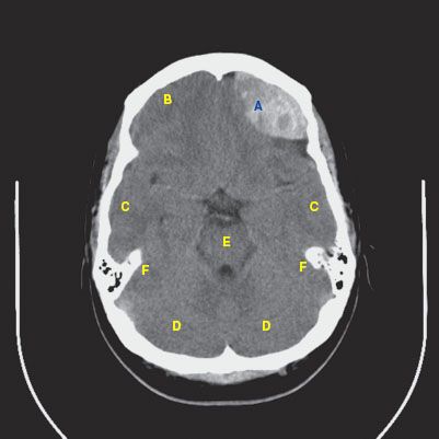
 CT findings (Fig. 12.1)
• Lentiform-shaped hyperdense area immediately deep to the skull, often in the temporal or parietal regions
• Does not cross cranial sutures
• Areas of hypodensity may indicate active hemorrhage
FIGURE 12.1
A. Epidural hematoma
B. Frontal lobe
C. Temporal lobe
D. Cerebellum
E. Pons
F. Petrous pyramid
Subdural Hematoma
 Hematoma between the dura and the cortex
 Due to tearing of bridging veins
 Concave appearance
RADIOLOGY
Subdural Hematoma
 CT findings (Fig. 12.2)
• Usually seen as hyperdense fluid layering over the cerebral convexities or along the falx cerebri which appears thickened
• If acute, the blood will be hyperdense, but if chronic, the blood will be mixed in density
• Blood decreases in density over time with a similar density to CSF after a few weeks to months
FIGURE 12.2 A–C
FIGURE 12.2 A
A. Subdural hematoma
B. Right-to-left midline shift
C. Lateral ventricles
D. Falx cerebri
E. Scalp hematoma
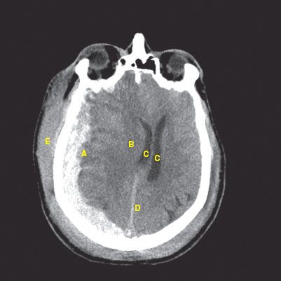
FIGURE 12.2 B
A. Subdural hematoma
B. Right-to-left midline shift
C. Lateral ventricles
D. Falx cerebri
E. Tentorium cerebelli
F. Cerebellum
G. Scalp hematoma
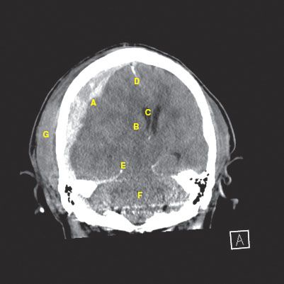
FIGURE 12.2 C
A. Subdural hematoma
B. Occipital lobe
C. Scalp hematoma
D. Tentorium cerebelli
E. Cerebellum
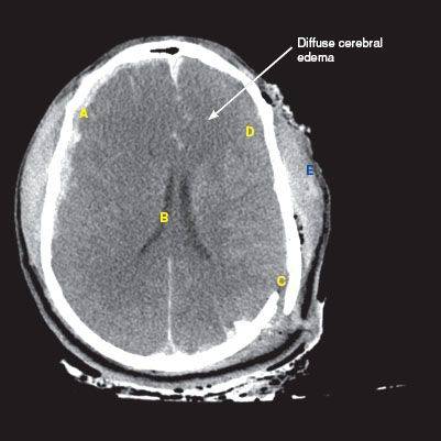
Subdural Hematoma with Diffuse Cerebral Edema
 CT findings (Fig. 12.3)
• Effacement of cerebral sulci, as well as the suprasellar and quadrigeminal plate cisterns
• Compression of ventricular systems may be seen
• Edema causes diffuse decreased attenuation of the brain parenchyma with loss of the gray–white junction
FIGURE 12.3
A. Subdural hematoma
B. Narrowed ventricles from edema
C. Parietal bone fracture
D. Loss of sulci
E. Diffuse scalp hematoma
Subarachnoid Hemorrhage
 Bleeding into the subarachnoid space (area between the pia mater and the arachnoid membrane)
 Disruption of vessels feeding the cortex
 Signifies traumatic brain injury
RADIOLOGY
Subarachnoid Hemorrhage (SAH)
 CT findings (Fig. 12.4)
• Hyperdense fluid that follows the sulci and gyri of the cerebrum (unlike subdural hemorrhages)
• Blood within the ventricles, cisterns, and spinal canal can also be seen
 MRI findings
• Dark, “blooming” artifact is seen with blood on T2* GRE
• Failure to suppress the CSF on FLAIR sequences may indicate blood (which appears as bright fluid around the cerebral sulci and hyri)
• If chronic SAH, a thin layer of T2 hypointense signal outlining the leptomeninges, especially in the basal cisterns can be seen
FIGURE 12.4 A–C
FIGURE 12.4 A
A. Subarachnoid hemorrhage
B. Falx cerebri
C. Lateral ventricles
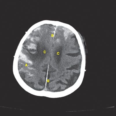
FIGURE 12.4 B
A. Subarachnoid hemorrhage
B. Falx cerebri
C. Anterior horn of lateral ventricles
D. Temporal horn of lateral ventricles
E. Third ventricle
F. Gyrus
G. Sulcus
H. Tentorium cerebelli
I. Pons
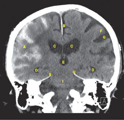
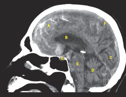
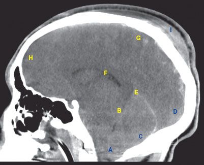
FIGURE 12.4 C
A. Subarachnoid hemorrhage
B. Lateral ventricle
C. Occipital lobe
D. Cerebellum
E. Pons
F. Parietal lobe
G. Pituitary
Brain Herniation
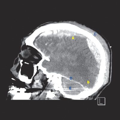
 CT findings (Fig. 12.5)
• Subfalcine herniation is the most common form of brain herniation
• Cingulate gyrus is displaced across the midline under the falx cerebri
• Compression of adjacent lateral ventricle may be seen
• Patients are at risk of anterior cerebral artery infarction in the distribution of the callosomarginal branch, where it is susceptible to compression against the falx cerebri
FIGURE 12.5 A–C
FIGURE 12.5 A
A. Subfalcine herniation
B. Left-to-right midline shift
C. Lateral ventricles
D. Posterior horn of lateral ventricles
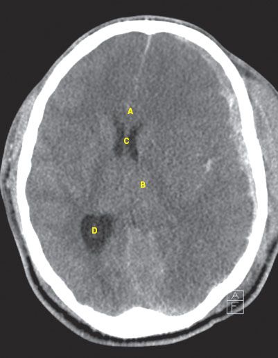
FIGURE 12.5 B
A. Subfalcine herniation
B. Subdural hematoma
C. Left-to-right midline shift
D. Lateral ventricles
E. Anterior horn of lateral ventricles
F. Subarachnoid hemorrhage

FIGURE 12.5 C
A. Tonsillar herniation
B. Transtentorial herniation
C. Cerebellum
D. Occipital lobe
E. Tentorium cerebelli
F. Lateral ventricle
G. Parietal lobe
H. Frontal lobe
I. Scalp hematoma
Intraparenchymal Hemorrhage
 Bleeding into the brain parenchyma
 Ranges from small contusions to large hematoma
Diffuse Axonal Injury
 Severe rotational forces lead to shear injury to white matter pathways
 Not directly seen on CT imaging but suggested by
• punctate hemorrhages
• loss of the gray/white matter differentiation
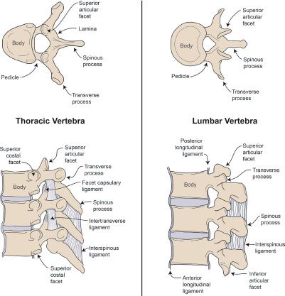
Spinal Injuries
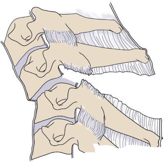
Overview (Illustration 1)
 Anterior column: Anterior half of the vertebral body and disc, anterior longitudinal ligament
 Middle column: Posterior half of the vertebral body and disc, posterior longitudinal ligament
 Posterior column: Pedicles, lamina, ligamentum flavum, transverse process, spinous process, articular process, supraspinous and interspinous ligaments, joint capsules
 Instability:
• Fracture that disrupts two of the three columns
• Compression with reduction of more than 50% of vertebral height
• More than 2.5 mm sagittal plane displacement of the vertebral body
• Angulation of more than 20 degrees in the sagittal plane
Illustration 1
Spine anatomy
Cervical Spine Injuries (C-spine)
 One-third occur at level of C2
 One-half occur at level of C6–C7
NEXUS (National Emergency X-Radiography Utilization Study) criteria—C-spine is determined to be stable if:
C-spine injuries
 GCS 15 (no neurologic deficit)
 No intoxication
 No painful distracting injury
 No focal neurologic deficit
 No posterior midline tenderness
RADIOLOGY
 Plain film findings
• Trauma series includes AP, lateral, and open mouth (odontoid views)
• Malalignment of any element within the cervical spine (vertebral bodies, facet joints, spinous processes, etc.)
• May see increased interspinous distance or widening of the intervertebral disc spaces
• Abnormal motion of the vertebrae with neck flexion and extension views indicate ligamentous injury
 CT findings
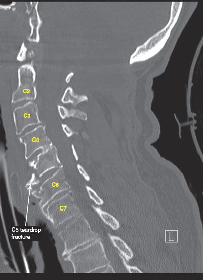
• More sensitive examination for cervical spine injuries (Fig 12.6 A-D)
• Provides more detail of the extent of injury seen on plain film
 MRI findings
• More sensitive examination for soft tissue injuries such as ligament tears
• Examination of choice to evaluate for spinal cord injuries
• Can detect epidural/subdural hematomas within the spinal canal
FIGURE 12.6 A–D
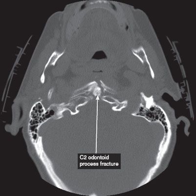
FIGURE 12.6 A
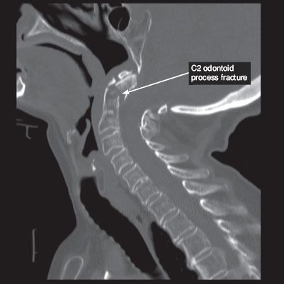
FIGURE 12.6 B
FIGURE 12.6 C
A. Vertebral body
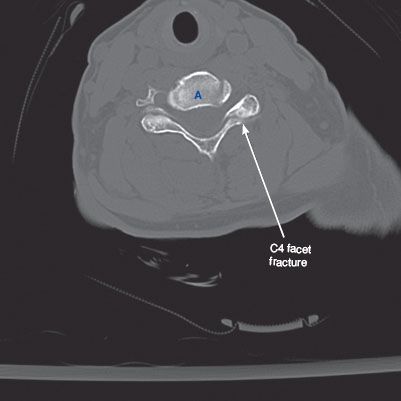
FIGURE 12.6 D
Flexion Injuries
 Simple wedge (Illustration 2)
• Anterior body wedging
• Decreased vertebral body height, increased density on imaging
• Stable
ILLUSTRATION 2
Simple wedge fracture

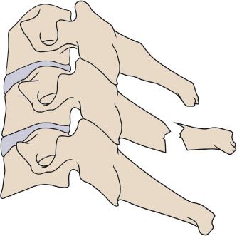
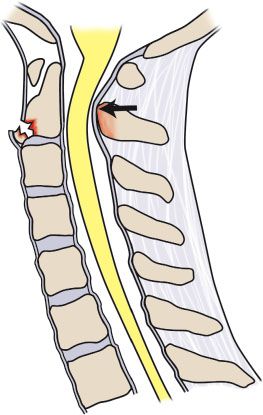
 Flexion teardrop (Illustration 3)
• Flexion with vertical axial compression
• Fracture of anteroinferior aspect of vertebral body with displacement
• Involves disruption of all three columns and associated with cord injury
• Unstable
ILLUSTRATION 3
Flexion teardrop

 Anterior subluxation (Illustration 4)
• Rupture of posterior ligamentous structures
• Widening of interspinous space seen on lateral view
• Stable, but rarely associated with neurologic deficit, most are treated as unstable
ILLUSTRATION 4
Anterior subluxation
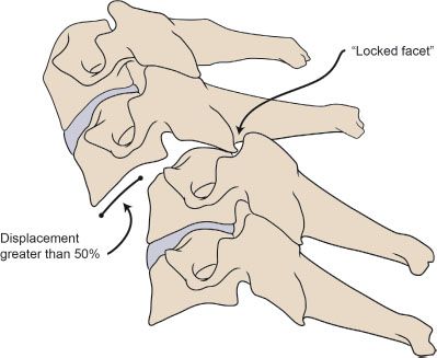
 Bilateral facet dislocation (Illustration 5)
• Anterior subluxation with displacement of more than half of AP diameter, resulting in a “locked facet”
• Associated with disk rupture
• Unstable
ILLUSTRATION 5
Bilateral facet dislocation
 Clay-shoveler (Illustration 6)
• Abrupt flexion with neck contraction
• Oblique fracture at base of spinous process, usually low C-spine
• Stable
ILLUSTRATION 6
Clay shoveler
 Flexion–rotation (Illustration 7)
• Unilateral facet dislocation
• Inferior facet of upper vertebra passes superior and anterior to superior facet of lower vertebra
• Disruption of posterior ligament
• Anterior displacement < one-half of AP diameter of body on lateral view
• Stable
ILLUSTRATION 7
Flexion–rotation
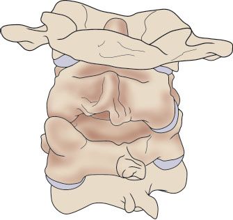
 Rotatory atlantoaxial dislocation (Illustration 8)
• Specific unilateral facet dislocation
• Asymmetry of C1 with respect to dens
• Unstable
ILLUSTRATION 8
Rotatory atlantoaxial dislocation

Extension Injuries
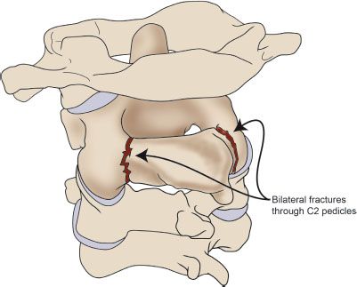
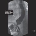
 Hangman fracture (Illustration 9)
• Traumatic spondylolisthesis of C2
• Bilateral fractures through pedicles of C2
• Rarely associated with spinal cord injury
• Unstable
ILLUSTRATION 9
Hangman fracture
 Extension teardrop (Illustration 10)
• Anterior longitudinal ligament pulls away inferior aspect of vertebra
• Hyperextension avulsion injury
• Common in diving accidents
• Unstable in extension (no traction)
• Stable in flexion
ILLUSTRATION 10
Extension teardrop
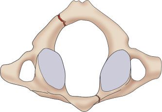
 Jefferson fracture (Illustration 11)
• Burst fracture ring of C1
• Fracture of anterior and posterior arches
• Unstable
ILLUSTRATION 11
Jefferson fracture
Thoracic and Lumbar Spine Injuries
RADIOLOGY
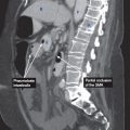
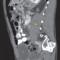
FIGURE 12.7 A,B
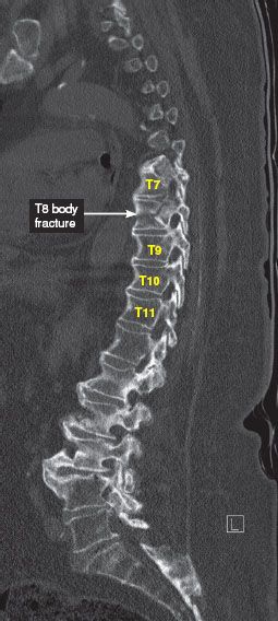
FIGURE 12.7 A
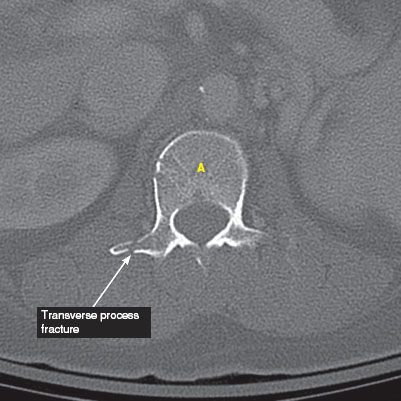
FIGURE 12.7 B
Flexion/Compression
 Wedge and compression fractures (Illustration 12)
• Anterior column only—stable
• Anterior and posterior column—potentially unstable
• Three column—unstable with possible cord, nerve root, or vascular injury
ILLUSTRATION 12
Wedge and compression fracture

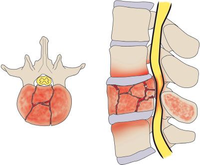
 Axial compression
• Burst fracture (Illustration 13)
• Anterior and middle columns compressed leading to loss of vertebral height
 Five subtypes:
1. Fracture of both endplates
2. Fracture of superior endplate (most common)
3. Fracture of inferior endplate
4. Burst rotation
5. Burst lateral flexion fracture
 Stable burst fractures do not involve posterior column
 Unstable burst fractures involve posterior column
 Imaging required to evaluate canal impingement
ILLUSTRATION 13
Burst fracture
Related posts:

Stay updated, free articles. Join our Telegram channel

Full access? Get Clinical Tree


