Traumatic Lesions of Bones and Joints
Lee F. Rogers
L. F. Rogers: Department of Radiology, Wake Forest University School of Medicine, Winston-Salem, North Carolina 27157.
Although a fracture may be obvious on clinical examination, roentgenograms are essential for precisely defining the nature and severity of the injury. In many instances, the clinical findings are questionable and a roentgen examination is necessary to determine whether a fracture is present. As a general rule, a roentgen examination should be performed if there is the slightest doubt concerning the possibility of a fracture or dislocation. After reduction of a fracture, roentgenograms are required to evaluate the accuracy of reduction and subsequently to monitor the progress of healing. No set rules can be given for the frequency of follow-up examinations, because the indications vary widely depending on the type of fracture, the bone involved, the method of treatment employed, and the age of the patient. A fracture treated by skeletal traction may require daily examinations, whereas a satisfactorily reduced and casted fracture may be examined only immediately after application of the cast and at intervals of several weeks thereafter until healing is complete.
METHODS OF EXAMINATION
Roentgenography
An accurate assessment requires at least two views made at right angles, usually an anteroposterior (AP) and a lateral projection. At times the fracture line is visible in only one of several projections (Fig. 2-1). A fracture cannot be ruled out solely on the basis of a roentgenogram in a single projection. Two views are also necessary to obtain a true perspective of the spatial relationships of the fragments (Fig. 2-2). An additional oblique projection is usually required to accurately assess trauma in the region of a joint. Because of superimposition, it is not possible to obtain technically satisfactory direct lateral radiographs of either the hip or the shoulder; some form of oblique projection is mandatory. The radiographic examination of a long bone should include the entire length of the bone, from the joint above to the joint below. Although this may not always be necessary for injuries of the ends of the bone, it is mandatory for those involving the shaft or diaphysis. Fractures of the shaft may be associated with injuries of an adjacent joint, particularly the proximal joint, and if this joint is not included in the radiographic examination such injuries may be overlooked.
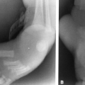
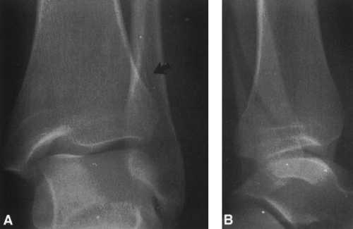 FIG. 2-1. Fracture of lateral malleolus identified with certainty on only one of two views. A: Anteroposterior view of the ankle demonstrates soft-tissue swelling about the lateral malleolus and a faint fracture line (arrow). B: Lateral view demonstrates obvious long oblique fracture of the lateral malleolus. |
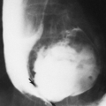
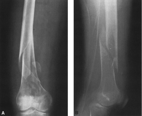 FIG. 2-2. Spiral fracture of the femur. A: Anteroposterior view. B: Lateral view. The distal fragment is angulated medially and offset posteriorly. There is minimal comminution of the fracture distally. The relationship between the fracture fragments is best appreciated by viewing the fracture in two planes, preferably at 90° to each other. |
A fracture that may have been very difficult to visualize initially usually becomes more obvious within 1 to 2 weeks because of resorption along the fracture edges (see Fig. 2-5).
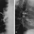
 FIG. 2-3. Fracture of carpal scaphoid. A: There is no obvious fracture of the scaphoid. B: Technetium bone scan demonstrates focus of increased radioactivity in the region of the scaphoid (arrow) and a general increase in the carpal joints as a result of traumatic synovitis. (Courtesy of Khalil Shirazi, M.D., Ann Arbor, Michigan.) |
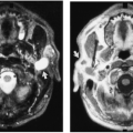
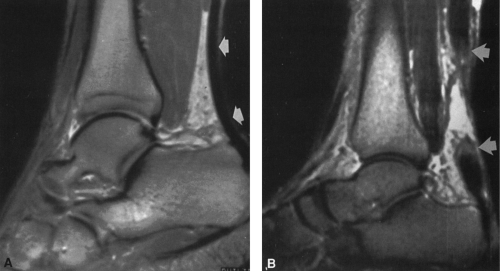 FIG. 2-4. Magnetic resonance image of the Achilles tendon. A: Normal T1-weighted image demonstrates the uniformly low-signal Achilles tendon (arrows). This is sharply defined anteriorly by the pre-Achilles fat pad. B: T2-weighted image of a torn Achilles tendon demonstrates an area of high signal interposed between the two ends of the torn tendon (arrows). The high signal is caused by a hematoma. The margins of the tendon are widened and contain irregular signal consistent with hemorrhage. |
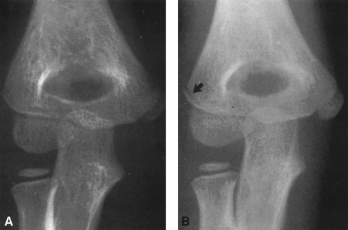 FIG. 2-5. Occult fracture of the lateral condyle of the humerus in a 4-year-old girl. A: Anteroposterior view demonstrates no definite fracture. B: Repeat examination 8 days later demonstrates a linear, hairline fracture of the lateral condyle (arrow). This is classified as a Salter-Harris type IV epiphyseal injury. |
Radioisotope Bone Scanning
Technetium-99m can be used in the assessment of skeletal trauma. The examination is obtained 2 hours after intravenous injection of the isotope. The isotope is localized in areas of increased bone turnover and therefore is concentrated at the margins of a fracture. Radioisotope bone scanning is more sensitive but less specific than roentgenographic examination of the skeletal system. Therefore, the isotope examination may disclose fractures that are not apparent on radiographic examination (Fig. 2-3). It is used under the following circumstances: (1) diagnosing of stress fractures,29 in which the radioisotope scan may be positive as long as 6 weeks before the fracture is evident on radiographic examination; (2) diagnosing otherwise occult injuries after trauma, particularly in the assessment of scaphoid and other carpal injuries; (3) establishing the diagnosis of a battered child; and (4) assessing of the full extent of injury in the patient with multiple injuries. The principal objective of the isotopic examination is to identify fractures that are not apparent on radiographic examination. If there is no evidence of increased radioactivity, then a fracture can safely be ruled out, except in elderly persons who have a slow metabolic rate of bone turnover. In the elderly, a repeat scan may be required as long as 72 hours after injection of the isotope to identify the fracture site. The isotopic bone scan is nonspecific;
areas of increased activity are also caused by tumors, arthritis, and metabolic bone disease. These must be ruled out before the diagnosis of fracture is accepted.
areas of increased activity are also caused by tumors, arthritis, and metabolic bone disease. These must be ruled out before the diagnosis of fracture is accepted.
Computed Tomography
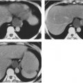
Computed tomography (CT) has distinct advantages in the assessment of skeletal trauma at certain sites.9,14 Because of the unique display of anatomy in the axial projection, these sites are usually difficult to evaluate by plain film radiography. CT is particularly useful in the evaluation of facial, spinal (see Fig. 2-32), pelvic, and acetabular fractures because it displays various components in isolation, free of overlap by surrounding structures (i.e., bony margins of sinuses, spinal canal, sacroiliac joint, sacral ala, hip joint, and anterior and posterior rims of the acetabulum). CT is also useful in the evaluation of the sternoclavicular joint and carpal and tarsal9 bones (see Fig. 2-69). Its greatest limitation is the difficulty in determining the relationship of one axial image to another in the sagittal or coronal planes. This problem may be overcome by image reconstruction in the appropriate plane. To do so requires both thin sections and the absence of patient movement between slices. Acutely injured patients often cannot hold still. Helical CT is distinctly advantageous because it affords shorter examination times and therefore decreases the likelihood of patient movement.
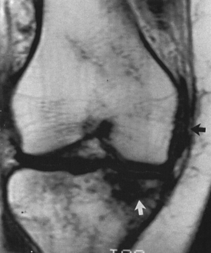 FIG. 2-6. Bone bruise or occult intraosseous fracture. The irregular area of low signal in the medial tibial plateau on this T1-weighted image indicates the presence of an intraosseous hemorrhage or bone bruise. Compare this signal with that of the lateral plateau and femoral condyles. Note also the irregular linear density in the midst of the surrounding irregular densities (white arrow). This represents a crack or undisplaced fracture. This injury was associated with a complete tear of the anterior cruciate ligament and a partial tear of the medial collateral ligament (black arrow). Compare with Fig. 2-63B. |
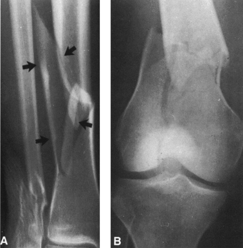 FIG. 2-7. A: Comminuted fracture of distal tibia with large butterfly fragment (arrows) and an associated fracture of the lateral malleolus. B: Comminuted T-shaped fracture of the distal end of the femur. In addition to the irregular transverse fracture through the shaft, there is a vertical fracture extending to the articular surface within the intercondylar notch. |
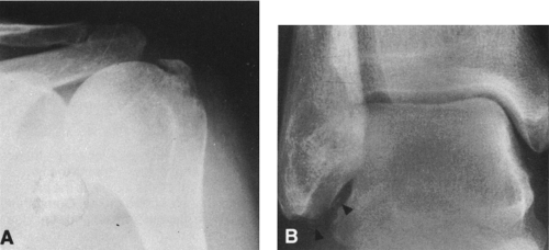 FIG. 2-8. A: Avulsion fracture of the greater tuberosity of the humerus. B: Soft-tissue swelling over the lateral malleolus is associated with small avulsion fractures (arrows) from the tip of the lateral malleolus. This is known as a sprain fracture. |
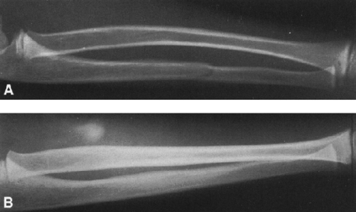 FIG. 2-9. Bow and greenstick fractures of the distal radius and ulna. A: Lateral view demonstrates anterior bowing of the radius without an obvious fracture line associated with a greenstick fracture of the midshaft of the ulna. B: Lateral view of opposite normal side for comparison. |
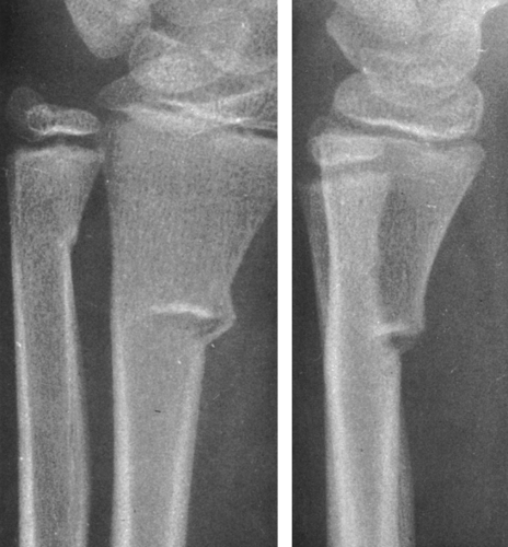 FIG. 2-10. Torus fractures of the distal radius and ulna. There is anterolateral buckling of both the radius and ulna, but despite the slight angulation of the distal fragments, the fracture line does not extend across the width of the shaft. |
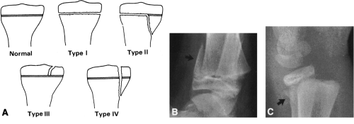 FIG. 2-11. Fractures of the epiphysis. A: Diagram of the Salter-Harris classification of epiphyseal fractures. Type V injury is not included, because there are no radiographic abnormalities at the time of the initial injury. B and C: Salter-Harris type II fracture of the distal tibia and radius. Note the large, triangular, metaphyseal fragment, the “corner sign” (arrow). There is an associated fracture of the distal fibula (B). Dorsal displacement of the distal radial epiphysis accompanied by a small triangular fragment (arrow) from the dorsal surface of the metaphysis (C). |
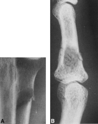 FIG. 2-12. Pathologic fractures. A: Carcinoma of the lung metastatic to the proximal radius. A transverse fracture has occurred through a lytic focus of metastatic disease. Note the endosteal erosion. B: Pathologic fracture through a phalangeal enchondroma. |
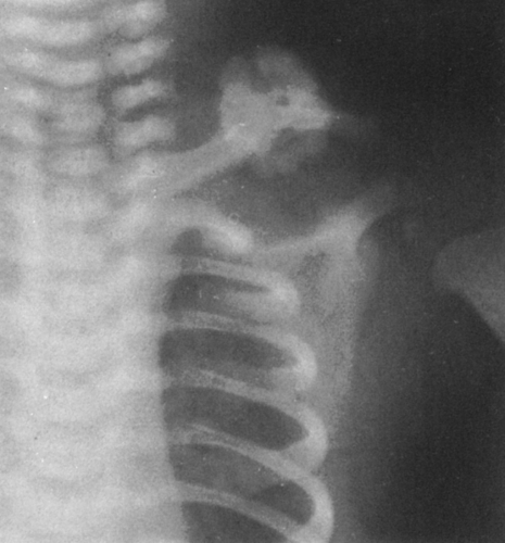 FIG. 2-13. A fracture of the left clavicle that occurred during birth. Examination at 2 weeks of age demonstrates a large amount of callus at the fracture site. |
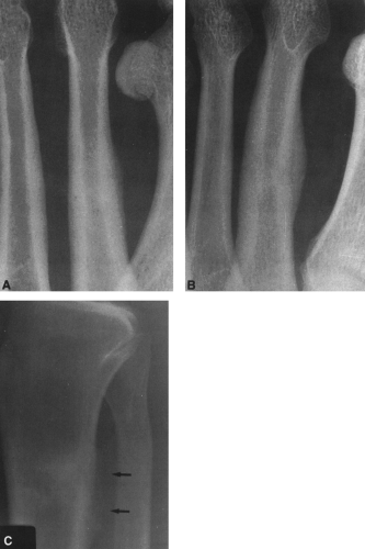 FIG. 2-14. Stress fracture. A and B: Stress fracture of the second metatarsal, the march fracture. Note the minimal subperiosteal new-bone formation along the medial aspect of the shaft (A). Examination 1 month later shows a considerable increase in the size of the callus at the fracture site (B). C: Stress fracture of the proximal tibia manifested by periosteal new-bone formation along the posterior cortex of the proximal tibia (arrows). |
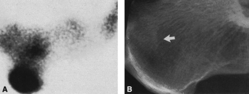 FIG. 2-15. Stress fracture of the calcaneus. A: Technetium bone scan reveals increased radioactivity in the posterior margin of the tuberosity of the calcaneus. B: Lateral radiograph demonstrates area of increased density caused by endosteal callus formation at the site of stress (arrow). (Courtesy of Joseph Norfray, M.D., Springfield, Illinois.) |
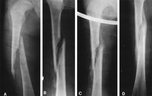 FIG. 2-16. Healing fractures. A: Injury shows long, oblique fracture of the midshaft of the femur. B: In 2 weeks, some hazy callus formation is identified at the margins of the fracture. C: At 4 weeks, considerable callus is evident. D: Three months after injury, there is a solid bridge of callus between fragments along the external surfaces. The fracture line is disappearing, indicating presence of endosteal callus. (Courtesy of Ralph C. Frank, M.D., Eau Claire, Wisconsin.) |
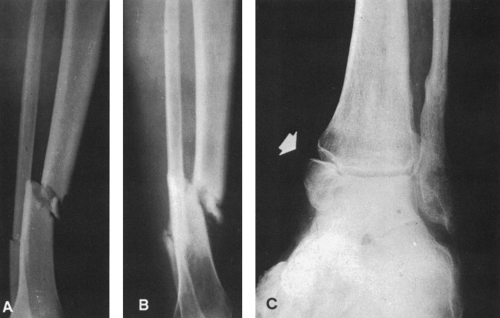 FIG. 2-17. Fracture nonunion. A: Comminuted tibial fracture and transverse fibular fracture 3 weeks after injury without callus formation. B: Eight months later there is partial union of the fibula, but no definite callus bridges the tibial fracture. There is some eburnation of bone adjacent to the tibial fracture site. C: Old nonunited fracture of the medial malleolus (arrow). |
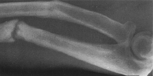 FIG. 2-18. Malunion of the radius with marked volar angulation at the fracture site associated with pseudoarthrosis of a fracture of the midshaft of the ulna. Note the bony eburnation at the fracture site and the formation of a false joint. |
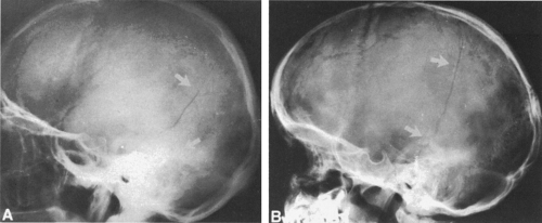 FIG. 2-19. Linear fracture of the skull. A: A linear fracture of the parietal bone extends posteriorly toward the occipital bone (arrow). B: In this patient, a linear fracture line extends into the posterior temporal bone from the parietal area (arrows). |
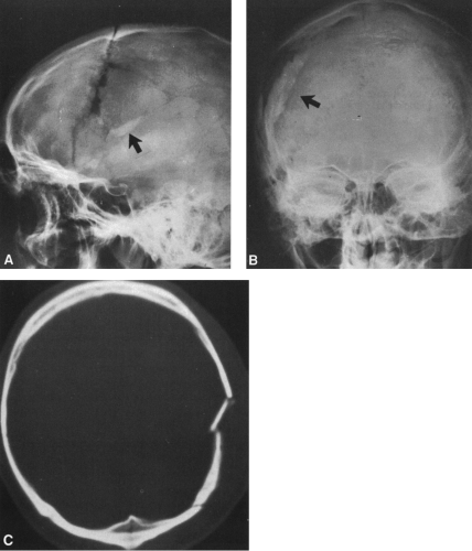 FIG. 2-20. Depressed comminuted skull fracture. A: Lateral view shows an irregular fracture line with overlapping that results in increased density (arrow). B: Anteroposterior view demonstrates the extent of depression. Note the inward displacement of the large bone fragment (arrow). C: Computed tomogram of another patient demonstrates typical findings of a depressed fracture. |
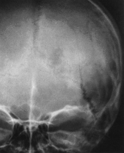 FIG. 2-21. Diastatic fracture. A linear fracture of the parietal bone extends into the lambdoidal suture with obvious widening of the suture line. |
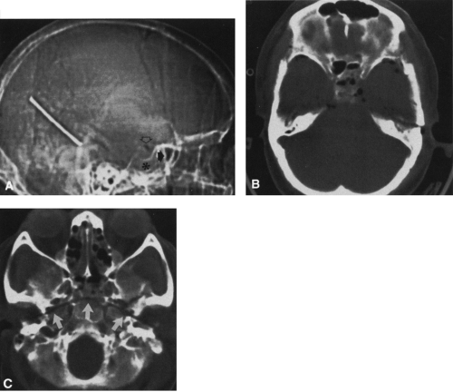 FIG. 2-22. Basal skull fracture with pneumocephalus. A: A digital radiograph of the skull demonstrates opacification of the sphenoid sinus (asterisk), air-fluid level in the posterior ethmoid sinuses (closed arrow), and pneumocephalus in the basal cisterns (open arrow). The linear metallic density is a hairpin that was left on the patient at the time of the examination. B: Computed tomogram demonstrates small bubbles of air within the subarachnoid space of the middle cranial fossa and opacification of the sphenoid and posterior ethmoid sinuses with air-fluid levels. C: An arcuate, transverse fracture of the base of the skull is shown (arrows). |
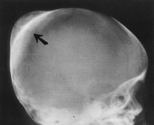 FIG. 2-23. Calcified cephalohematoma (arrow) after birth trauma. The dense, calcified mass shown here gradually decreased in size and eventually disappeared. |
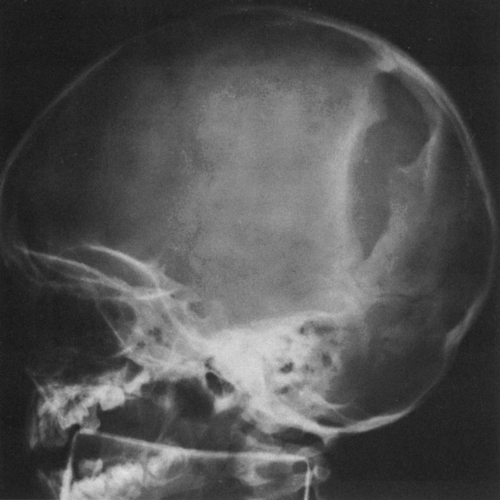 FIG. 2-24. A leptomeningeal cyst or growing fracture caused by meningeal adhesions to the inner margins of an old linear fracture. Swelling was noted over the region of previous fracture several months after injury. The elongated, slightly elliptical lucency with slightly sclerotic margins is characteristic of a leptomeningeal cyst. |
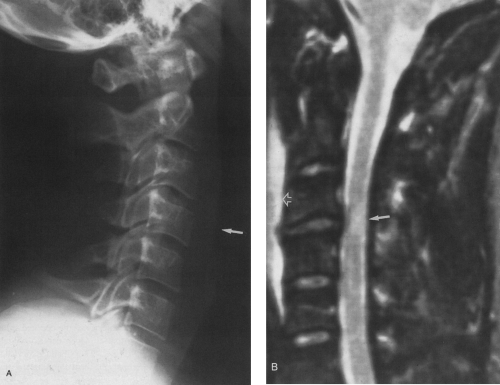 FIG. 2-25. Spinal cord contusion sustained in auto accident as a result of hyperextension of the neck. A: Lateral plain film demonstrates retropharyngeal soft-tissue swelling measuring 10 mm anterior to C4 (arrow). No evident fracture or dislocation is seen. B: T2-weighted sagittal magnetic resonance image reveals spinal cord contusion (arrow) and prevertebral hemorrhage and edema (open arrow). |
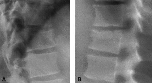 FIG. 2-26. Compression fracture of the 12th thoracic vertebra. A: Lateral view demonstrates anterior wedged compression of the 12th vertebral body. The anterosuperior margin of this vertebra is irregular. The posterior wall of the vertebra remains intact. B: Tomogram demonstrates the findings with clarity. Note the zone of increased radiodensity in the upper portion of the vertebral body, representing impaction of bone. |
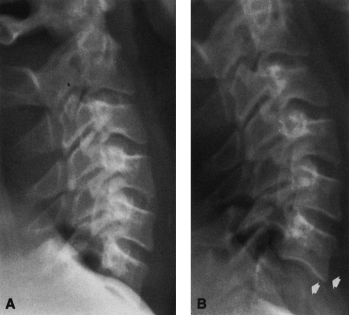 FIG. 2-27. All seven cervical vertebrae must be seen on the film. A: Initial cross-table lateral view demonstrates only six cervical vertebrae without apparent injury. B: Lateral view repeated while pulling down on the arms demonstrates a fracture-dislocation of C6-C7 (arrows). |
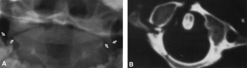 FIG. 2-28. Jefferson fracture of C1. A: Open-mouth view demonstrates lateral displacement of the lateral masses of C1 in relation to C2 (arrows). No fracture is evident, however. Normally, the lateral masses of Cl should align with the lateral masses of C2. B: CT reveals a fracture of the anterior arch of C1 and of the junction of the posterior arch with the lateral mass and an incomplete fracture of the posterior arch. |
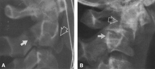 FIG. 2-29. Fractures of C2. A: Hangman’s fracture of C2. Note the fractures of the neural arch (arrow) associated with fracture of the inferior margin of the vertebral body (open arrow) and overlying soft-tissue swelling. B: Fracture of the dens with anterior displacement. Note the relationship of the posterior cortical margin of the dens (open arrow) with the posterior cortical margin of the vertebral body (arrow). |
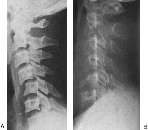 FIG. 2-30. Fractures of the lower cervical spine. A: Hyperflexion strain of the fourth on the fifth cervical vertebra. The fourth cervical vertebra is displaced anteriorly on the fifth, and the facet joints are disrupted. B: Teardrop fracture of C5. Note the characteristic triangular anterior fragment and the posterior displacement of C5 relative to C6. |
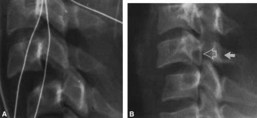 FIG. 2-31. Facet locking of the cervical spine. A: Bilateral facet locks. Anterior displacement of C4 on C5 exceeds 50% of the width of the vertebral body. The facets of C4 have come to rest in front of the facets of C5. B: Unilateral facet lock. There is anterior displacement of C5 on C6 approximating 25% of the width of the vertebral body. The vertebral bodies below the dislocation are in lateral profile, whereas those above are in oblique profile. The closed arrow points to the undisplaced facet and the open arrow to the rotated and locked facet. |
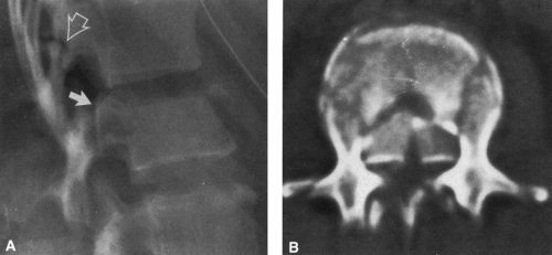 FIG. 2-32. Burst fracture of the second lumbar vertebra. A: Lateral view demonstrates the anterior wedged compression of the second lumbar vertebral body. Note the retropulsion of the posterosuperior margin of the vertebral body (arrow), which compromises the spinal canal. There is also a horizontal fracture through the lamina of L1 (open arrow). B: Retropulsion of a split fragment, with marked compromise of the spinal canal. There is also a fracture of the left lamina. The superior surface of the vertebral body is comminuted. Fractures of the transverse processes are also present. |
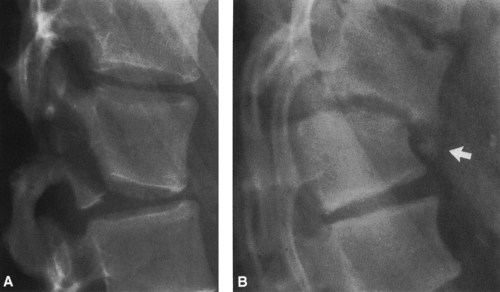 FIG. 2-33. Fractures of the thoracolumbar spine. A: Chance fracture of the second lumbar vertebra. Note the absence of compression of the vertebral body. A horizontal fracture has extended through the lamina, the base of the pedicles, and the inferior posterior margin of the vertebral body. The L2-L3 disc is disrupted. B: Fracture-dislocation of T11-T12. There is anterior displacement of T12, and a characteristic small triangular fragment is displaced from the anterosuperior margin of T12 (arrow). |
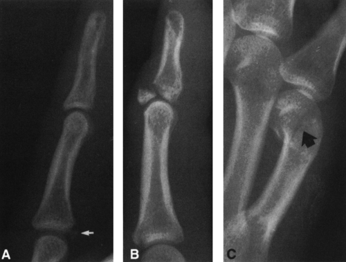 FIG. 2-34. Fractures of the phalanges. A: Volar plate avulsion from the base of the middle phalanx (arrow). The fragment is characteristically quite small. B: Baseball finger, with characteristic fracture of the dorsal surface at the base of the distal phalanx. C: Boxer’s fracture of the neck of the fifth meta-carpal (arrow), with characteristic volar displacement of the distal fragment. |
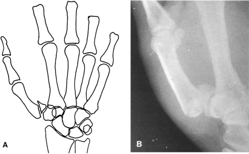 FIG. 2-35. Bennett’s fracture of the first metacarpal. A: Diagram illustrating the characteristic deformity. B: Radiograph showing lateral displacement of the shaft and characteristic oblique fracture of the base of the metacarpal. |
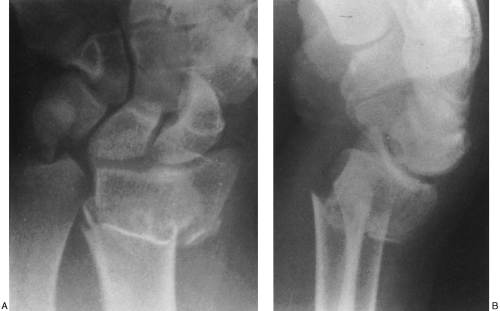 FIG. 2-36. Colles’ fracture. A: Note the comminution and posterior lateral impaction. The ulnar styloid has been avulsed and is faintly seen lateral to its normal position. B: Note the characteristic posterior angulation of the distal fragment. |
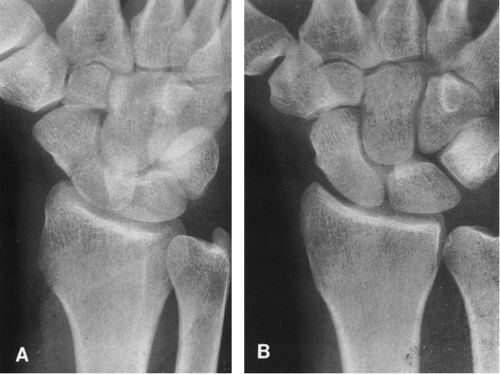 FIG. 2-37. Fracture of the waist of the scaphoid. Note that the fracture line is observed on the oblique projection (A) but not on the posteroanterior view (B). |
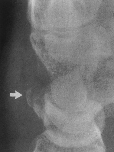 FIG. 2-38. Lateral view of the wrist demonstrates characteristic small avulsion of the dorsal surface of the triquetrum (arrow) and overlying soft-tissue swelling. |
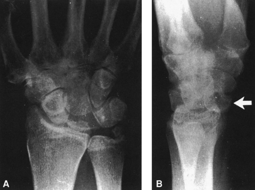 FIG. 2-39. Anterior dislocation of the lunate. In the posteroanterior view (A), disruption of the normal joint space between the proximal and distal rows of the carpus is noted. On the lateral view (B), the lunate is displaced anteriorly (arrow) and has the profile of a quarter moon. |
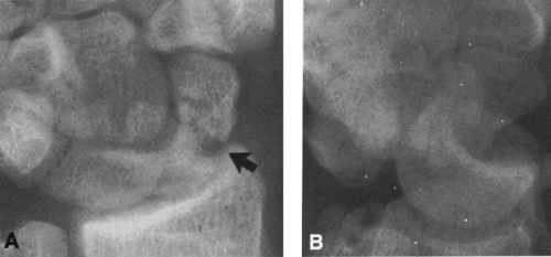 FIG. 2-40. Trans-scaphoid posterior perilunate dislocation. A: Posteroanterior view of the wrist demonstrates a widely displaced fracture of the scaphoid (arrow) and an apparent overlap of the distal and proximal rows of the carpal bones. B: Lateral view demonstrates posterior displacement of the distal carpal row relative to the proximal carpal row with slight tilting of the lunate. |
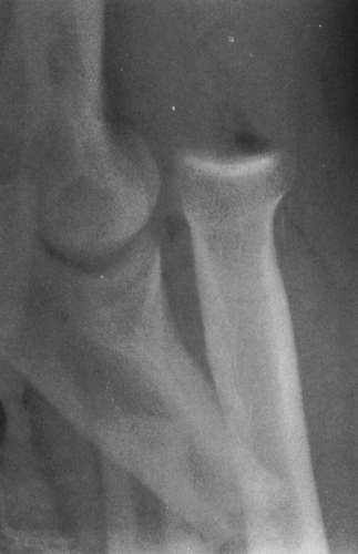 FIG. 2-41. Monteggia’s fracture-dislocation of the elbow. There is an angulated fracture of the proximal third of the ulna, with overriding of the fracture fragments associated with anterior dislocation of the radius. This is an open injury evidenced by air within the joint and soft tissues. |
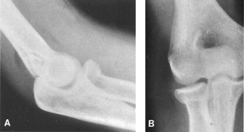 FIG. 2-42. Impacted fracture of the radial head with hemarthrosis. A: The fat pads are identified as lucencies anterior and posterior to the lower humeral shaft. In the absence of a joint effusion, the posterior fat pad should not be seen. Visualization of the posterior fat pad is referred to as a positive fat pad sign. B: An impacted fracture of the neck of the radius is identified as a linear band of density at the junction of the radial head and neck. |
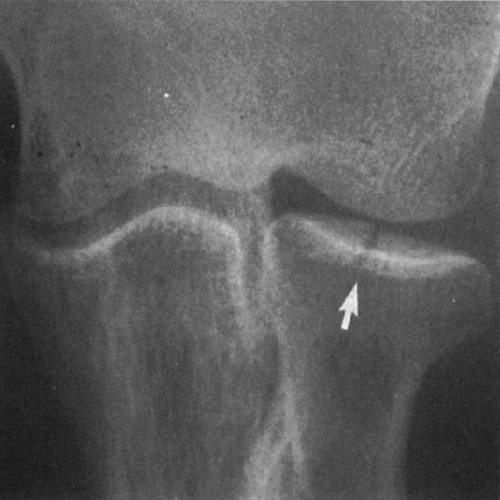 FIG. 2-43. A characteristic linear fracture of the radial head (arrow). |
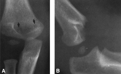 FIG. 2-44. Supracondylar or transcondylar fracture of the humerus in a 19-month-old child. A: Anteroposterior view demonstrates transverse fracture line (arrows). B: Lateral view reveals incomplete greenstick fracture, with posterior displacement of the articular margin. |
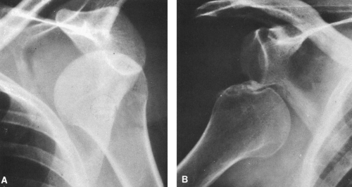 FIG. 2-45. Anterior dislocations of the shoulder. A: Subcoracoid, anterior dislocation with characteristic displacement of the humeral head. The head lies anterior to the glenoid and beneath the coracoid process of the scapula. B: A chronic anterior dislocation of the shoulder. Note the indentation of the humeral head (Hill-Sachs) caused by impaction against the rim of the glenoid. |
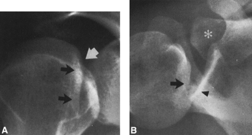 FIG. 2-46. Posterior dislocation of the shoulder. A: Anteroposterior view demonstrates that the humeral head is held in internal rotation, characteristic of a posterior dislocation. Note the impaction fracture manifested by a notch on the medial margin of the humeral head (white arrow) and the “trough line” (black arrow). B: Axillary view demonstrates the impaction fracture of the humeral head (arrow) and posterior displacement of the humeral head in relation to the posterior rim of the glenoid (arrowhead). An asterisk marks the lateral margin of the clavicle. |
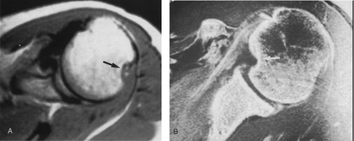 FIG. 2-47. Axial magnetic resonance images of the left shoulders of two different patients with history of previous glenohumeral dislocations. A: Previous anterior dislocation, now reduced. Note Hill-Sachs defect (arrow) in characteristic location, posterolateral aspect of humeral head. B: History of previous posterior dislocation. Note characteristic defect located anteromedially in the humeral head (arrow). |
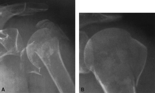 FIG. 2-48. Fractures of the proximal humerus. A: Comminuted fracture with pseudodislocation. Note that there are fractures of the surgical neck and avulsions of both the greater and lesser tuberosities. The humeral head is laterally and inferiorly displaced because of a large hemarthrosis. This gives the false appearance of a dislocation and therefore is designated a pseudodislocation. B: Impacted fracture of the surgical neck of the humerus, with avulsion of the greater tuberosity. |
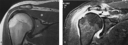 FIG. 2-49. A: Normal coronal oblique projection, proton density image of the shoulder demonstrates intact supraspinatus tendon (arrow) and muscle (asterisk). A, acromion; D, deltoid muscle; G, glenoid of scapula. B: Full-thickness tear of supraspinatus tendon, fat-saturated, T2-weighted image. The tendon (arrow) is retracted medially. Fluid is present in the joint, and the joint is contiguous with the subacromial bursa. |
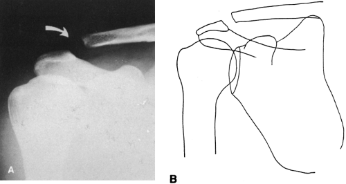 FIG. 2-50. Third-degree acromioclavicular separation. A: The joint is widened (arrow), and the clavicle is displaced superiorly. There is also an abnormal separation between the clavicle and the coracoid, indicating a disruption of the coracoclavicular ligaments. B: A line drawing of this injury. |
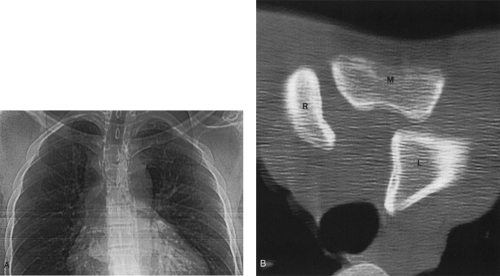 FIG. 2-51. Posterior dislocation of left sternoclavicular joint. A: Digital radiograph demonstrates that the left clavicle is slightly inferior to the right clavicle. B: Computed tomogram reveals head of left clavicle (L) posterior to manubrium of sternum (M). The head of the right clavicle (R) is in normal position. |
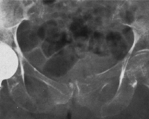 FIG. 2-52. Fractures of the superior and inferior pubic rami. The inferior pubic ramus fracture is impacted. |
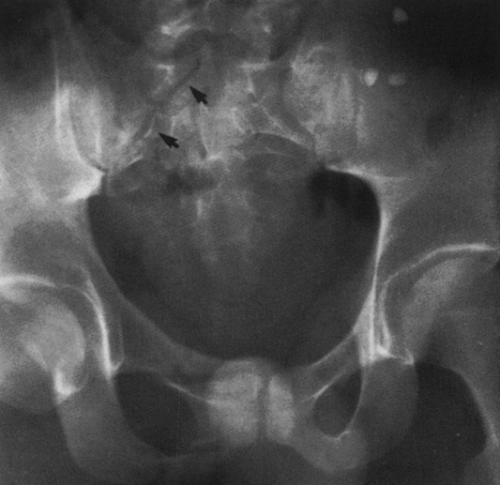 FIG. 2-53. Malgaigne’s fracture of the pelvis. Fractures of the pubis and an oblique fracture extending through the right sacral ala (arrows) disrupt the sacral foraminal lines. Note the intact foraminal lines in the left sacral ala. |
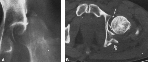 FIG. 2-54. Posterior dislocation of the hip. A: Anteroposterior view demonstrates characteristic posterosuperior displacement of the femoral head, with numerous surrounding fragments from the posterior wall of the acetabulum. B: Computed tomogram obtained after reduction of the fracture demonstrates fractures of the posterior rim of the acetabulum (large arrow) and small fragments entrapped within the joint (small arrows). |
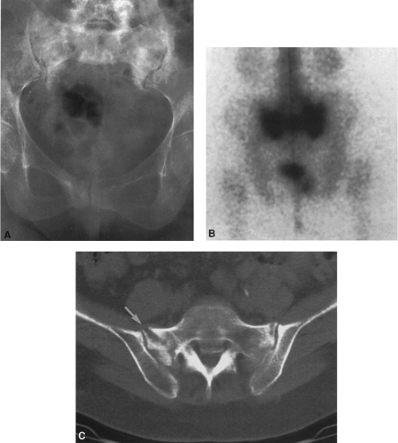 FIG. 2-55. Insufficiency fractures of the pelvis. A and B: Case 1: An 82-year-old osteoporotic woman with low-back pain. Anteroposterior film (A) demonstrates mottled sclerosis of the sacrum and body of the right pubic bone. Bone scan (B) demonstrates typical H-type pattern in the sacrum and increased radioactivity in the right pubis beneath the bladder. C: Case 2: Computed tomography scan of insufficiency fracture of the sacrum in a 71-year-old osteoporotic woman. A linear, lucent fissure is in the right sacral ala (arrow) and is surrounded by sclerosis. Note the absence of a soft-tissue mass. There is also a small insufficiency fracture in the anterior portion of the left sacral ala. |
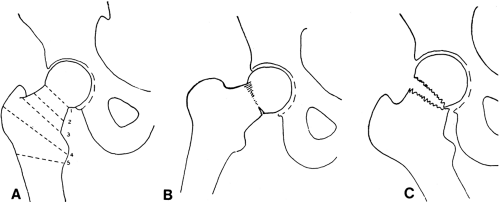 FIG. 2-56. Diagram of fractures of the proximal femur. A: The usual sites of fracture are 1, subcapital; 2, transcervical; 3, basicervical; 4, intertrochanteric; and 5, subtrochanteric. B: Impacted subcapital fracture. C: Displaced subcapital fracture. |
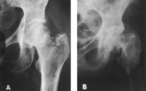 FIG. 2-57. Two fractures of the femoral neck. A: Impacted subcapital fracture. Note the characteristic distortion of the superolateral margin of the junction of the head and neck, with a vague zone of increased density caused by impaction along the course of the subcapital fracture. B: Nonimpacted subcapital fracture. The shaft is drawn proximally and is externally rotated. The margins of the fracture are not in apposition. |
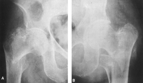 FIG. 2-58. Two intertrochanteric fractures. A: There is a comminution of the greater trochanter. B: This fracture involves the lesser trochanter and is highly unstable. |
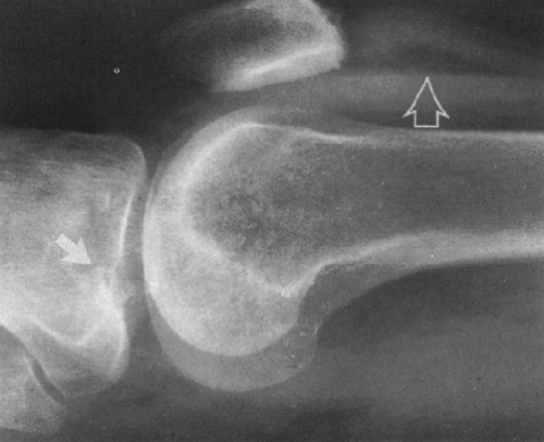 FIG. 2-59. Lipohemarthrosis of the knee. A cross-table lateral view with a horizontal beam demonstrates a fat-fluid level in the suprapatellar bursa (open arrow) caused by a fracture of the lateral tibial plateau (arrow). |
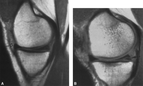 FIG. 2-60. Magnetic resonance image of the medial meniscus. A: Normal medial meniscus. Note the typical triangular shape of the anterior (arrow) and posterior horns of the medial meniscus. There is a very low signal within the medial meniscus that does not extend to the joint surface. This is a normal finding. Note the medium signal of the joint cartilage and the high signal of the intermedullary bone. B: Torn posterior horn of the medial meniscus. Linear, low signal extends through the substance of the meniscus to the joint surface (arrow). The inferior portion of the meniscus is difficult to see by arthroscopy, and this tear could easily be overlooked. |
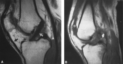 FIG. 2-61. Magnetic resonance image of the anterior cruciate ligament. A: T1-weighted image demonstrates normal ligament (white arrow). Note also the infrapatellar ligament (black arrow) and the quadriceps tendon (open arrow). B: Torn anterior cruciate ligament. There is no clear demonstration of the substance of the tendon. The normal signal of the tendon is replaced by an ill-defined mass of intermediate signal (arrow). Note also the presence of a joint effusion in the suprapatellar bursa (asterisk). |
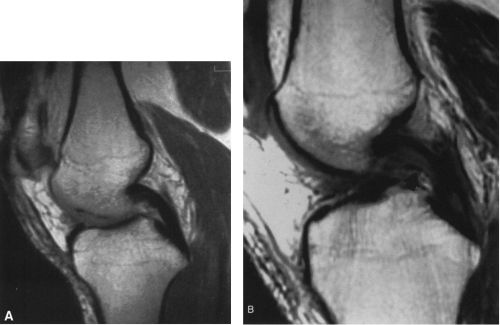 FIG. 2-62. A: Normal posterior cruciate ligament (PCL) is identified as a solid black band of low intensity that extends in a smooth convex arc from the posterior surface of the medial femoral condyle to the posterior intercondylar surface of the tibia. B: T1-weighted, coronal image demonstrates extensive region of high signal in the PCL (arrow), indicative of partial tear. |
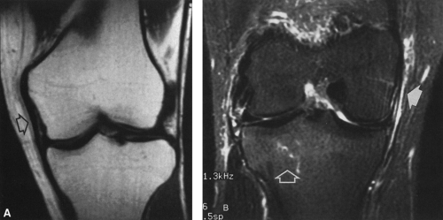 FIG. 2-63. A: Normal medial collateral ligament (MCL) is visualized as a thin, linear, dark band of low signal extending from the medial femoral condyle to the medial surface of the tibial plateau (arrow). B: Fat-suppressed, T2-weighted coronal image demonstrates edema and hemorrhage about torn MCL (arrow) and bone bruise in the tibial plateau (open arrow). |
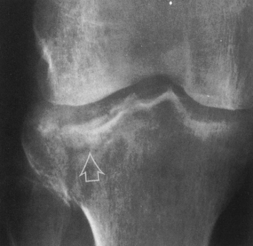 FIG. 2-64. Fracture of the lateral tibial plateau. There is a vertical component laterally and a depression of the joint surface (arrow). |
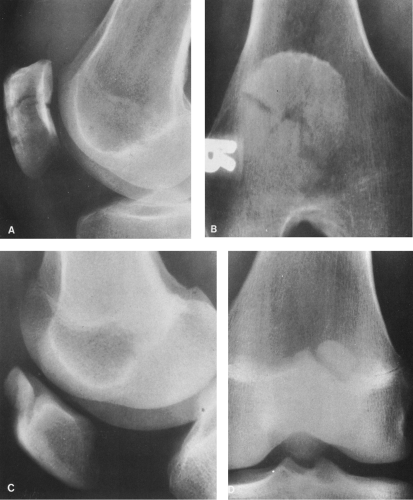 FIG. 2-65. A and B: Undisplaced fracture of the patella. C and D: Bipartite patella showing smooth cortical surfaces and characteristic location on the superolateral margin of the patella. The margins are not as sharply defined as in fracture. |
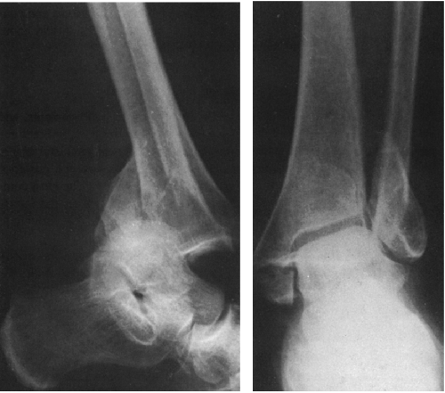 FIG. 2-66. Fracture-dislocation of the ankle. There are fractures of the medial and lateral malleolus and the posterior malleolus (posterior tubercle) of the tibia. The malleolar fragments are characteristically displaced posteriorly with the foot. |
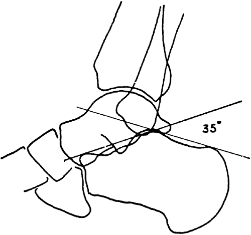 FIG. 2-67. Böhler’s angle, the tuber-joint angle of the calcaneus. Diagram illustrates the method for determining this angle, which is normally between 20° and 40°. |
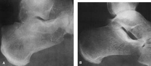 FIG. 2-68. Compression fracture of the os calcis. A: Note the characteristic loss of Böhler’s angle and impaction of fracture fragments manifested by an increase in density without an obvious line of fracture. B: Normal os calcis for comparison. |
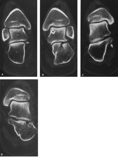 FIG. 2-69. Comminuted fracture of the left calcaneus examined by computed tomography in the axial plane. A: Normal right calcaneus at the level of the posterior facet of the subtalar joint (arrow). B: Comminution of the left calcaneus that extends into the posterior facet. A small bone island is present within the talus (asterisk). C: Scan through the normal right sustentaculum (arrow). D: Corresponding image on the left demonstrates a fracture separating off the sustentaculum tali. There is also a comminuted fracture of the lateral wall of the calcaneus. T, tibia; L, lateral malleolus of fibula; Ta, talus; C, calcaneus. |
Magnetic Resonance Imaging
Magnetic resonance imaging (MRI)6,8,12 provides direct visualization of soft-tissue structures, including ligaments, tendons, joint capsules, menisci, and joint cartilages—structures that are impossible to see on plain film radiographs and often not clearly distinguishable by CT (Fig. 2-4). It has the added advantage of displaying these structures in any longitudinal plane (i.e., sagittal, parasagittal, coronal, or oblique) in addition to the axial plane.
MRI, like radioisotopic bone scanning, is more sensitive than radiography and can detect intraosseous injuries that are not apparent on plain films5 (see Fig. 2-6). MRI is useful in the detection of stress,11 insufficiency, and otherwise obscure fractures of the femoral neck and other sites.
MRI is used in the assessment of meniscal and ligamentous injuries of the knee and the rotator cuff and labrum of the shoulder, as well as traumatic disorders of other joints, including the wrist, spine, and ankle. MRI is also commonly used in the evaluation of tendons, particularly the Achilles, quadriceps, and infrapatellar tendons.
TYPES OF FRACTURES
There are several ways in which fractures can be classified. They are easily divided into two major groups, open and closed fractures. An open fracture, previously known as a compound fracture, denotes a fracture in which there is a perforation, laceration, or avulsion of the overlying skin and soft tissues. The importance of an open fracture lies in the possibility of infection because of contamination at the time of injury. This possibility must be taken into account when follow-up roentgenograms of an open fracture are being evaluated. A closed fracture, one in which the overlying skin and soft tissues are intact, may be converted into an open fracture by the need for open surgical reduction and internal fixation with metallic plates, bone grafts, or other fixation devices. Although it infrequently occurs with good surgical technique, infection is always possible after such procedures.
Terminology
When describing displacement of fracture fragments, it is customary to refer to the displacement of the distal fragment
in relation to the proximal, the latter being considered as the stationary part. Therefore, one speaks of a posterior displacement of the distal fragment of the tibia in relation to the proximal fragment rather than an anterior displacement of the proximal in relation to the distal. The same method is used in describing dislocations, the distal portion of the extremity being considered to be the dislocated part. For example, all dislocations of the elbow joint are displacements of the bones of the forearm on the humerus. In describing angular deformity, the distal fragment should be considered as being angled in relation to the proximal fragment. Therefore, a fracture of the distal tibia with lateral displacement of the foot would be described as lateral angulation of the distal fragment. As an alternative, the angulation may be defined at the fracture site. In the case described with lateral displacement of the foot, there would be medial angulation at the fracture site. The more common method is to describe the angulation of the distal fragment. Apposition, overlap or overriding, and number of fragments are other important observations.
in relation to the proximal, the latter being considered as the stationary part. Therefore, one speaks of a posterior displacement of the distal fragment of the tibia in relation to the proximal fragment rather than an anterior displacement of the proximal in relation to the distal. The same method is used in describing dislocations, the distal portion of the extremity being considered to be the dislocated part. For example, all dislocations of the elbow joint are displacements of the bones of the forearm on the humerus. In describing angular deformity, the distal fragment should be considered as being angled in relation to the proximal fragment. Therefore, a fracture of the distal tibia with lateral displacement of the foot would be described as lateral angulation of the distal fragment. As an alternative, the angulation may be defined at the fracture site. In the case described with lateral displacement of the foot, there would be medial angulation at the fracture site. The more common method is to describe the angulation of the distal fragment. Apposition, overlap or overriding, and number of fragments are other important observations.
The following groupings of fractures are useful for descriptive purposes, and the terms are those used in the roentgen and clinical evaluations. Some fractures do not fit into a specific group because they show mixed features. For example, a compression fracture may also show evidence of comminution; the line of demarcation between an impacted fracture and a compression fracture is not sharp; and a Colles’ fracture at the wrist is usually comminuted as well as impacted. These limitations must be kept in mind when one attempts to classify any specific fracture.
Complete and Incomplete Fractures
The term complete is used to designate a fracture that caused a complete discontinuity or disruption of bone with separation into two or more fragments. An incomplete fracture does not extend across the entire width of the bone.
Occult Fractures
An occult fracture is one that is strongly suspected by physical examination but not visualized roentgenographically on the initial evaluation. These fractures may be demonstrated on a subsequent radiographic examination, because deossification occurs along the edge of the fracture line (Fig. 2-5) and makes the fracture more readily visible. Such fractures may be detectable by bone scanning or MRI before they can be demonstrated by radiographic examination (see Fig. 2-3).
Bone Bruise
MRI evaluation of suspected meniscal or ligamentous injuries of the knee has revealed incidental intraosseous abnormalities that have been termed occult intraosseous fractures12,26 but are popularly referred to as bone bruises. They appear as irregular areas of high signal intensity on T2-weighted images within the subchondral medullary space. T1-weighted and proton density images (Fig. 2-6) show ill-defined, speckled areas of low signal intensity in these same areas. Occasionally, a linear or branching band of signal void is identified within the same area. Radioisotopic bone scans may show increased activity. These abnormalities can be identified in both the medial and lateral femoral condyles and the tibial plateau.
Bone bruises are presumed to represent hemorrhage and edema associated with trabecular microfractures sustained as the result of compression or impaction forces applied to the joint surface. They often are associated with meniscal or ligamentous injuries but may occur as isolated findings. Similar lesions can occur in the joint margins of other bones.
Hairline Fractures
A hairline fracture is an undisplaced fracture with minimal separation of the fracture fragments. The fracture line is so fine that it is compared to the width of a single hair (see Fig. 2-37).
Comminuted Fractures
A comminuted fracture is composed of more than two fragments. Occasionally the bone may be extensively shattered,
but more often comminution is less severe and the fracture has a fairly distinct pattern. For instance, a triangular-shaped fragment at one margin of a shaft fracture is referred to as a butterfly fragment (Fig. 2-7A). Fractures that are at the end of the bone and that extend intra-articularly commonly do so in a T-, V-, or Y-shaped pattern, and these letters are used to describe the nature of the comminution. For instance, a T-shaped fracture in the lower end of the femur consists of a transverse fracture extending across the width of the bone in the supracondylar area and a vertical extension into the knee joint between the two condyles (Fig. 2-7B).
but more often comminution is less severe and the fracture has a fairly distinct pattern. For instance, a triangular-shaped fragment at one margin of a shaft fracture is referred to as a butterfly fragment (Fig. 2-7A). Fractures that are at the end of the bone and that extend intra-articularly commonly do so in a T-, V-, or Y-shaped pattern, and these letters are used to describe the nature of the comminution. For instance, a T-shaped fracture in the lower end of the femur consists of a transverse fracture extending across the width of the bone in the supracondylar area and a vertical extension into the knee joint between the two condyles (Fig. 2-7B).
Avulsion and Chip Fractures
In an avulsion fracture, a fragment of bone is pulled away or avulsed from a tuberosity or bony process at the end of a bone at a site of ligament or tendon attachment (Fig. 2-8A). When the fragment is very small, it may be referred to as a chip or sprain fracture. These small cortical avulsions, also known as flake fractures, frequently occur in the ankle as a result of ankle sprains (Fig. 2-8B) and are also commonly encountered in the finger, where the fragments are often tiny (see Fig. 2-34).
Segmental Fractures
Two or more complete fractures may involve the shaft of a single bone. These differ somewhat from the more common form of comminuted fracture in that each is complete, leaving a segment of intact shaft between them. They are known as segmental fractures. In the common comminuted fracture, one or more small fragments have been separated along the line of a major fracture, but these pieces as a rule do not include the entire width of the bone.
Impacted Fractures
In an impacted fracture, the fragments are driven into one another, either along the entire line of fracture or along only one side. A radiolucent fracture line may not be seen, because impaction completely obscures it. Instead, the line of impaction is denser than normal because of the condensed bony trabeculae within it. In addition, an impacted fracture can be recognized by the disruption of normal bone trabeculae at the site of impaction and by the sharp angulation of the cortical margin at least on one side of the fracture. Two of the more common impacted fractures are the Colles’ fracture of the distal radius (see Fig. 2-36) and the subcapital fracture of the neck of the femur (see Fig. 2-57A). Impacted fractures are also frequent in the vertebral bodies (see Fig. 2-26) and os calcis (see Fig. 2-68), where they are usually referred to as compression fractures.
Greenstick Fractures
Greenstick fractures occur almost exclusively during infancy and childhood. The appearance of such a fracture is similar to that obtained by trying to break a green twig. There are three basic forms of greenstick fractures.22,23 In the first, a transverse fracture occurs in the cortex, extends into the midportion of the bone, and then becomes oriented along the longitudinal axis of the bone without disrupting the opposite cortex (Fig. 2-9). The second form is a torus or buckling fracture (Fig. 2-10). This is caused by impaction. The cortex is buckled and overlapped, but there is no distinct disruption of the cortex. The third form is a bow fracture, in which the bone becomes curved along its longitudinal axis but with no distinct buckle or break in the cortex (Fig. 2-9). The bow
fracture is most commonly encountered in the forearm, less commonly in the fibula, and rarely in the femur, clavicle, and humerus.
fracture is most commonly encountered in the forearm, less commonly in the fibula, and rarely in the femur, clavicle, and humerus.
Epiphyseal Fractures
During childhood, a fracture may extend either partly or completely through the epiphyseal plate at the end of a long bone and may lead to displacement of the epiphysis on the shaft. This most commonly occurs at age 10 through 16 years and is most frequently encountered in the distal end of the radius, in the phalanges, and in the lower end of the tibia.23,24 If the line of fracture is limited to the cartilage, it will not be directly visible and its detection will rest on the evidence of epiphyseal displacement or on variation in width of the epiphyseal line. In the absence of displacement, detection of a pure epiphyseal plate fracture is difficult; comparison with the opposite extremity is helpful in doubtful cases. In most cases, the fracture does not remain confined to the cartilaginous plate but angles sharply into the bone so that a corner fragment of the metaphysis remains attached to and displaced with the epiphysis. If there is no displacement, the oblique fracture line in the metaphysis indicates the nature of the injury.
Because the epiphysis is responsible for bone growth, injuries involving the epiphyseal growth plate may result in an alteration in length of the involved bone. In children, dislocations and ligamentous tears are uncommon. Injuries that cause these conditions in adults produce epiphyseal separations in the younger age group. The extent of the injury is important in assessing the likelihood of growth alterations. Prognosis depends on the degree of vascular damage, with growth disturbance paralleling the degree of arterial disruption. The Salter-Harris classification is commonly used to describe injuries of the epiphyseal plate (Fig. 2-11A).24,25 Radiographic findings are distinct for each type, and prognosis usually varies with type. In general, injuries involving the lower extremity have a much more serious prognosis than those of the upper extremity, irrespective of the type. The classification is as follows:
Type I
This is a pure epiphyseal separation. The line of cleavage is confined to the zone of hypertrophic cells within the epiphyseal plate. Because the fracture line is in the cartilage, it is not visible radiographically; displacement of the epiphyseal ossification center is the only positive radiographic sign. The prognosis is generally favorable, with no alterations in growth in most instances.
Type II
A fragment from the metaphysis accompanies the displaced epiphysis, separating a segment of bone on the metaphyseal side (Fig. 2-11). This is by far the most common injury, accounting for approximately 75% of cases. The most common site is the distal radius, which accounts for up to one half of all epiphyseal injuries. The distal tibia, distal fibula, distal femur, and ulna are involved in decreasing order of frequency. The prognosis is generally favorable except at the ankle or knee.
Type III
The fracture runs vertically through the epiphysis and through the growth plate. A portion of the epiphysis is detached and displaced. Usually the displacement is minimal, without an associated fracture of the metaphysis. The most common site is the distal tibia. The prognosis is good if the fragment is replaced properly so that the joint surface does not become irregular.
Type IV
This is a vertically oriented fracture that extends through the epiphysis and growth plate and into the metaphysis. The fracture fragment consists of a portion of metaphysis, growth plate, and epiphysis. The most common sites are the lateral condyle of the humerus in patients younger than 10 years of age and the distal tibia in those older than age 10. Growth arrest and joint deformities are the distinct hazard in
this type of injury, although the incidence is reduced by proper reduction and surgical fixation.
this type of injury, although the incidence is reduced by proper reduction and surgical fixation.
Type V
This rare injury is a result of crushing-type force, usually directed to the distal femoral or the proximal or distal tibial epiphyseal centers. It is most commonly associated with fractures of the shaft of the femur or tibia. There is no immediate visible radiographic alteration within the epiphyseal complex. Subsequently, some shortening or angulation occurs. Premature closure of an epiphyseal line and a slowing of the growth rate are the factors that result in deformity. Patients must be observed for a minimum of 2 years before the possibility of these complications can be ruled out.
Pathologic Fractures
A pathologic fracture is one occurring through diseased bone, characteristically resulting from a relatively trivial injury. Most are encountered in adults and are associated with foci of metastatic carcinoma (Fig. 2-12A) or, much less frequently, with a benign cause such as Paget’s disease or benign tumor, particularly an enchondroma of the phalanges (Fig. 2-12B). The lesions responsible for most pathologic fractures in children are benign. Patients with simple bone cysts of the proximal humerus or other sites often present with a pathologic fracture. Patients with osteogenesis imperfecta are subject to frequent fractures.
Pathologic fractures are often transversely oriented at right angles to the longitudinal axis of the long bone. The ends of the fragments are often smooth or slightly irregular. Comminution is infrequent. In such cases, the fragment should be observed carefully for evidence of bone destruction, endosteal erosion, or periosteal new-bone formation indicating a pre-existing lesion.
Pseudofractures
Pseudofractures are transverse, fissure-like defects that extend partly or completely through the bone. They are frequently seen in osteomalacia and are sometimes called looser zones or umbauzonen. They are infractions of bone in which osteoid is formed in the defect but there is no calcium deposition. Healing is delayed, and the fissure persists as a roentgenographically visible defect. Multiple pseudofractures of this type were described by Milkman in 1930, and the condition sometimes is called Milkman’s syndrome. Most investigators now believe that this represents osteomalacia in which the pseudofractures happen to be a particularly prominent part of the disease (see Osteomalacia in Chapter 6).
Related posts:
Stay updated, free articles. Join our Telegram channel

Full access? Get Clinical Tree


