Ocular and Orbital Soft Tissue Anatomy
An understanding of ocular anatomy is critical to appreciating how trauma can affect distinct parts of the orbit and globe. The globe has an anterior segment containing aqueous humor and a posterior segment containing more viscous vitreous humor (▶ Fig. 11.1). The anterior segment is further divided into an anterior and posterior chamber separated by the iris. The lens is situated posterior to the iris and is held in suspension by zonular radial fibers of the ciliary body. The globe has three layers: an outer fibrous sclera, a middle vascular choroid, and an innermost neural layer (the retina). The sclera is continuous anteriorly with the conjunctiva, and the choroidal layer attaches to the ora serrate at the level of the ciliary body anteriorly. The ocular muscles are in the conal space and are surrounded by a fibrous layer called the tenons capsule. The muscles attach to the globe via their respective tendons and pierce the sclera at their points of attachment. The optic nerve sheath contains the optic nerve, veins, and lymphatics. The sheath itself is a dural reflection. The central retinal artery lies outside the sheath.
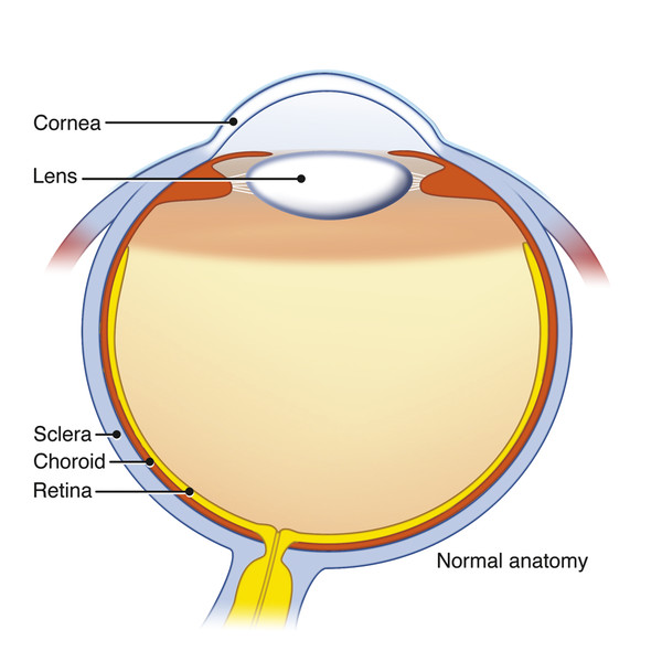
Fig. 11.1 Illustration showing the layers and structures of the normal globe.
11.3 Orbital Imaging Modalities
11.3.1 Volume Computed Tomography
Computed tomography (CT) is the primary modality for assessing orbital soft tissue and bony injury in the emergency setting. CT scanning of the orbits is very quick, which significantly reduces motion artifacts. The following discussion assumes a volume CT technique using a multidetector scanner when referring to CT. Volume CT also allows multiplanar reformations in any desired plane. It can distinguish a variety of soft tissue orbital injuries, including foreign bodies, gas, edema, hemorrhage, and ocular injures. CT is also useful for assessing bone thickness, fracture, and displacements, as well as intracranial complications. The major concern with orbital CT is the radiation dose to the ocular lens. Current-generation CT scanners are able to decrease the radiation dose by at least 50% compared with earlier CT scanner generations. In addition, using volume scanning to reconstruct coronal and sagittal reformations eliminates the need for direct coronal scans, which in combination with axial scans, doubles the radiation dose to the lens. A further disadvantage of direct coronal orbital imaging was that it was often significantly degraded by dental metallic streak artifact. CT angiography also can be performed rapidly to assess adjacent vascular injury of the internal carotid (ICA) and external carotid artery (ECA) branches.
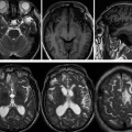
11.3.2 Magnetic Resonance Imaging
Magnetic resonance imaging (MRI) of the orbit is less frequently used than CT is in the setting of traumatic injury. MRI of the orbit requires more time and a cooperative patient who can hold his or her eyes relatively still. In acute orbital trauma, any suspicion of a potential foreign body in the orbit needs initial evaluation by CT to exclude a metal foreign body. If no foreign body is suspected or if a metal foreign body has been excluded by CT, then MRI may have a limited role in evaluating orbital soft tissue injury and any associated intracranial complications of the trauma.
Ultrasound
Radiologists in the United States do not commonly use ultrasound for orbital trauma, but ophthalmologists may use it in their office to quickly locate an intraocular foreign body, retinal detachment, or choroidal detachment. This testing is particularly useful if direct visualization via ophthalmoscopic examination is obscured by intraocular hemorrhage. Ultrasound of the orbit is highly sensitive and specific for globe injury and is easy to implement in the emergency department setting. Ultrasound, however, must not be used in the setting of known or suspected globe rupture because it could potentially aggravate the injury.
11.4 Fractures of the Bony Orbit
Fractures can involve any of the bones that border the bony orbit. These bones include frontal, zygomatic, lacrimal, ethmoid, and sphenoid bones. Orbital fractures may be isolated (e.g., blowout fracture, orbital rim fracture) or part of a more complex maxillofacial or skull-base fracture (e.g., zygomaticomaxillary fracture, Le Fort II or III fracture, naso-orbito-ethmoid fracture, orbital apex fracture, and sphenoid wing fracture). A combination of several patterns of fracture may coexist. Classification of fractures involving the orbit is a means of simplifying the description of the injury.
11.4.1 Blowout Fracture
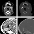
An orbital blowout fracture refers to two kinds of fractures that can occur through the weakest portions of the orbit: (1) medial orbital wall with the thin weak lamina papyracea of the ethmoid bone (▶ Fig. 11.2); and (2) orbital floor with the linear weak infraorbital canal (▶ Fig. 11.3). These fractures do not involve the orbital rim and are usually a result of blunt trauma from an object larger than the orbital rim, such as a fist or softball. The most common complications of this fracture are dysfunction of the medial rectus in a medial wall fracture or dysfunction of the inferior rectus with an orbital floor fracture (▶ Fig. 11.4; ▶ Fig. 11.5). The extraocular muscles may be edematous or have an intramuscular hematoma.
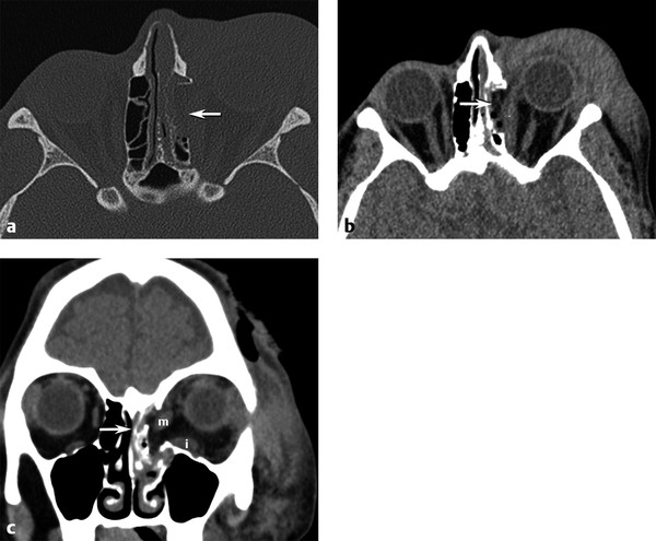
Fig. 11.2 Medial orbital blowout fracture. (a) Axial bone and (b) axial and (c) coronal computed tomography soft tissue images demonstrate an acute medial orbital blowout fracture (arrow) of the left orbit, with medial herniation of the medial rectus muscle into the ethmoid sinus fracture. Moderate periorbital soft tissue swelling is present. Note the distortion and swelling of both the left medial (m) and inferior (i) rectus muscles on the coronal view.
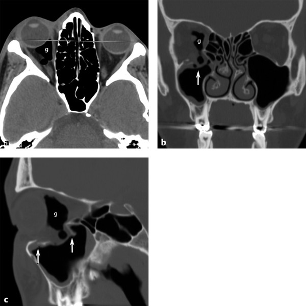
Fig. 11.3 Orbital floor blowout fracture. (a) Axial computed tomographic view showing right globe proptosis and retro-ocular gas (g). (b) Coronal bone image shows depressed right orbital floor fracture with orbital fat and retro-ocular gas herniating (vertical arrow) into the defect. (c) Sagittal view demonstrates the anterior and posterior extent (vertical arrows) of the depressed floor fracture.
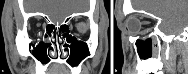
Fig. 11.4 Inferior extraocular muscle distortion. (a) Coronal and (b) sagittal computed tomographic views showing only fat herniating into the depressed orbital floor defect (arrow) but associated edema and distortion of the inferior rectus muscle (i) without downward herniation. Note the hemorrhagic air-fluid level (H) in the maxillary sinus on the sagittal view.
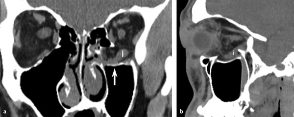
Fig. 11.5 Inferior extraocular muscle distortion. (a) Coronal and (b) sagittal soft tissue computed tomographic images of the acute left orbit depressed floor fracture(arrow) with both fat and inferior rectus muscle (i) herniation into the defect. Although the inferior rectus muscle is displaced, it is not entrapped by bone.
In addition, displacement or entrapment may occur through the bony defect (▶ Fig. 11.6; ▶ Fig. 11.7). Subperiosteal hematoma is either not present or is a minor component of this injury. Subperiosteal abscess is a rare complication of blowout fracture (▶ Fig. 11.8). Anesthesia of the maxillary division of cranial nerve V may occur if the fracture involves V2 in the infraorbital canal. Surgical repair with an implant reinforcing the floor or wall is often recommended in the first week or two after injury to prevent fibrosis and scarring from causing permanent muscular dysfunction (▶ Fig. 11.9).
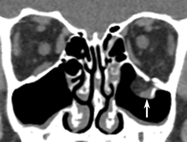
Fig. 11.6 Inferior extraocular muscle entrapment. Coronal computed tomographic view shows acute left orbital blowout fracture with both fat and inferior rectus muscle (vertical arrow) entrapped below the orbital floor.
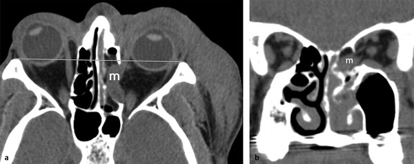
Fig. 11.7 Medial extraocular muscle entrapment. (a) Axial and (b) coronal computed tomographic images demonstrate complete herniation and entrapment of the swollen medial rectus muscle (m) into the acute medial orbital wall defect with associated enophthalmos.
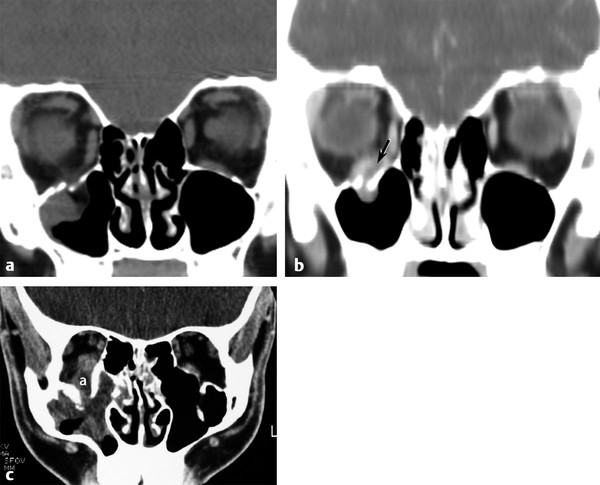
Fig. 11.8 Abscess complicating blowout fracture. (a) Coronal computed tomographic (CT) images showing an acute right orbital floor fracture. (b) Coronal CT in the same patient 3 weeks later returning with proptosis and pain showing a new subperiosteal abscess (arrow) between the inferior rectus and the orbital floor. (c) A different patient returned to the emergency department after being punched in the right eye a week earlier, now experiencing redness and swelling of the right orbit. Note the subperiosteal abscess (a) elevating the inferior rectus muscle and the associated maxillary sinus inflammation.
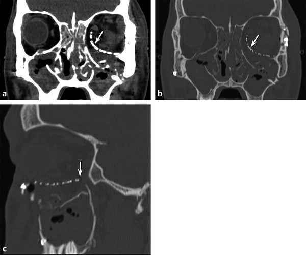
Fig. 11.9 Postoperative repair blowout fracture. (a) Coronal soft tissue and (b) bone computed tomographic images show a large depressed left medial and inferior orbital floor defect repaired with the placement of a curved mesh implant (arrow) underneath the inferior rectus muscle to approximate the normal position of the new orbital floor. (c) Sagittal image indicates the anterior-posterior extent (arrow) of the implant.
11.4.2 Orbital Roof Fracture
Fractures of the orbital roof are usually seen in combination with extension of linear frontal bone fractures or with complex cranial-facial fractures, including Le Fort III, naso-orbito-ethmoidal (NOE), skull-base fractures extending into the anterior skull base. A supraorbital subperiosteal hematoma is commonly seen (▶ Fig. 11.10; ▶ Fig. 11.11), which often causes acute ocular proptosis. These are usually treated noninvasively unless a bone fragment is rotated or displaced with impingement on the superior muscle complex or optic nerve.
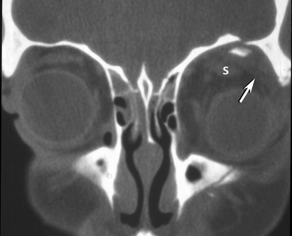
Fig. 11.10 Orbital roof fracture. Coronal computed tomographic image showing an inferiorly displaced orbital roof fracture fragment with an associated subperiosteal hematoma (arrow) displacing the superior muscle complex (s) and globe inferiorly.
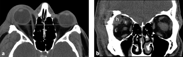
Fig. 11.11 Postoperative subperiosteal hematoma. (a) Axial computed tomography shows proptosis of the right globe. (b) Coronal image demonstrates postoperative superolateral right subperiosteal hematoma (h) from a pterional craniotomy, which is causing an intraorbital mass effect and displacing the superior (s) muscle complex and lateral (L) rectus muscle.
11.4.3 Blow-In Fracture
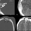
A blow-in fracture is an uncommon subtype of orbital roof fracture. A high-velocity projectile penetrating the skull and passing through the brain causes a blow-in fracture. The shock wave from the projectile causes a caudal or downward directed force on the floor of the anterior cranial fossa, resulting in comminuted, inferiorly displaced fractures through one or both orbital roofs (▶ Fig. 11.12).
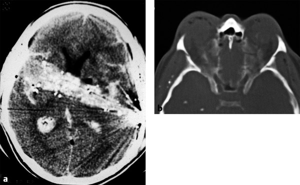
Fig. 11.12 Orbital blow-in fracture. (a) Axial head computed tomography shows a gunshot wound traversing the frontal lobes and basal ganglia with a high density hemorrhagic tract. (b) Axial bone windows show bilateral comminuted orbital roof fractures depressed down into the obits by the shock wave of the bullet traversing the brain.
11.4.4 Zygomaticomaxillary Fracture
This relatively common facial fracture has gone by several names: tripod fracture, trimalar fracture, and now zygomaticomaxillary (ZMC) fracture. These fractures are usually caused by blunt-force injury to the malar eminence of the body of the zygoma. The fractures essentially pass through or near the zygoma’s sutures with adjacent bones, including the frontozygomatic, zygomatico-maxillary, and the zygomatico-temporal sutures. A ZMC fracture may be nondisplaced or have both a displacement and rotary component. By definition, the fractures involve the lateral and inferior orbital rim, orbital floor, and lateral orbital wall (▶ Fig. 11.13). Anesthesia from the orbital floor fracture crossing the infraorbital canal may injure V2, the maxillary division of cranial nerve V. Subperiosteal hematomas or intrasinus hemorrhage may also occur with this injury. Displaced fractures are usually treated with surgical fixation along the lateral or infraorbital rim.
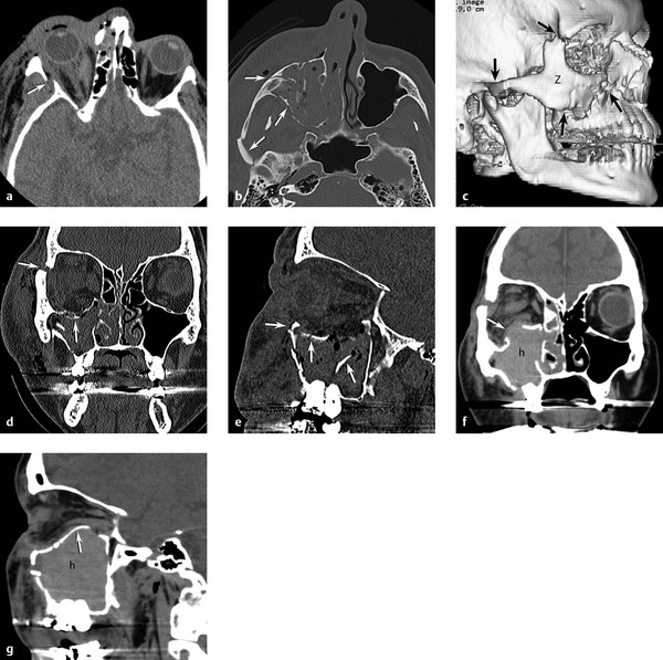
Fig. 11.13 Zygomaticomaxillary complex (ZMC) fracture. (a) Axial computed tomography (CT) through midorbit shows lateral orbital wall fracture (arrow) and retro-ocular hemorrhage. (b) Axial CT through maxillary sinus shows zygomatic arch and maxillary wall fractures (arrows). (c) Three-dimensional CT reformations showing ZMC fractures (arrows) with free zygomatic (Z) bone fragment. (d) Coronal and (e) sagittal images demonstrating a depressed orbital floor, infraorbital rim, and frontozygomatic suture fractures (arrows) with hemorrhage in the maxillary sinus. (f) Coronal and (g) sagittal repeat CT 4 hours later showing increased maxillary sinus bleeding (h) with unusual reversal of the orbital floor fracture now herniating up into the orbit (arrow) causing new proptosis.
11.4.5 Le Fort II and Le Fort III Fractures
Le Fort fractures are seen with high-velocity or high-impact energy blunt trauma, most commonly with a victim in a high-speed motor-vehicle collision. Le Fort injuries are usually bilateral and involve the pterygoid plates and the nasal septum. Orbital involvement is seen only in Le Fort II and Le Fort III fractures. A Le Fort II fracture passes through the infraorbital rim and medial orbit (▶ Fig. 11.14a,b). It may injure V2 if it passes through the infraorbital canal or foramen. A Le Fort III fracture passes through the frontozygomatic suture, lateral orbital wall, orbital floor, and medial orbit (▶ Fig. 11.14c–f). V2 injury may be seen with this injury as well. Intraorbital soft tissue and subperiosteal hematomas are common. Ocular injury may be present. Displaced Le Fort fractures are usually treated operatively with plates.
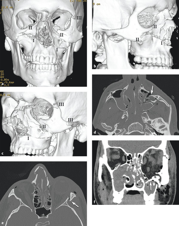
Fig. 11.14 Le Fort fractures. (a) Three-dimensional (3D) computed tomography (CT) reformat anteroposterior view shows complex Le Fort injury with bilateral Le Fort I, right Le Fort II, and left Le Fort III fractures. (b) 3D CT reformat right oblique view shows that this Le Fort II fracture involves the right infraorbital rim, anterior-lateral maxilla, and nasal arch, sparing the zygomatic arch and frontozygomatic suture. (c) 3D CT reformat left oblique view shows Le Fort III fracture through infraorbital rim, nasal arch, frontozygomatic suture, and zygomatic arch resulting in a free zygomatic fragment. (d) Axial CT shows medial and posterior rotation (arrow) of free zygomatic fragment (z) in left complex Le Fort I and III fracture. (e) Axial CT demonstrates Le Fort III fracture on the left with lateral orbital wall (arrow) and nasal arch and bilateral anterior ethmoid fractures. Le Fort II on right spares lateral orbital wall. (f) Coronal CT shows left orbital floor displaced fracture (arrow) as a component of the left Le Fort III injury.
11.4.6 Naso-Orbito-Ethmoid
A naso-orbito-ethmoid (NOE) fracture may be more accurately described as a naso-ethmoid-frontal fracture pattern. This fracture is most commonly caused by a blunt-force injury to the central midface, nose, and frontal bones (▶ Fig. 11.15a,b). It tends to fracture the medial buttresses but spares the lateral buttresses of the face. This injury drives the anterior portion of the ethmoid bone and/ or glabella of the frontal bone posteriorly or the glabella of the frontal bone posteriorly, telescoping the impacted bones into the deeper midface. Hypertelorism with widening of the interpupillary distance is common and is caused by the lateral expansion of the collapsed anterior ethmoid complex (▶ Fig. 11.15c–f). Involvement of the nasolacrimal duct may cause epiphora as a result of obstruction of lacrimal drainage. Ocular and retro-ocular soft tissue injury is often present. Displaced naso-ethmoid-frontal fractures are usually treated operatively with plates.
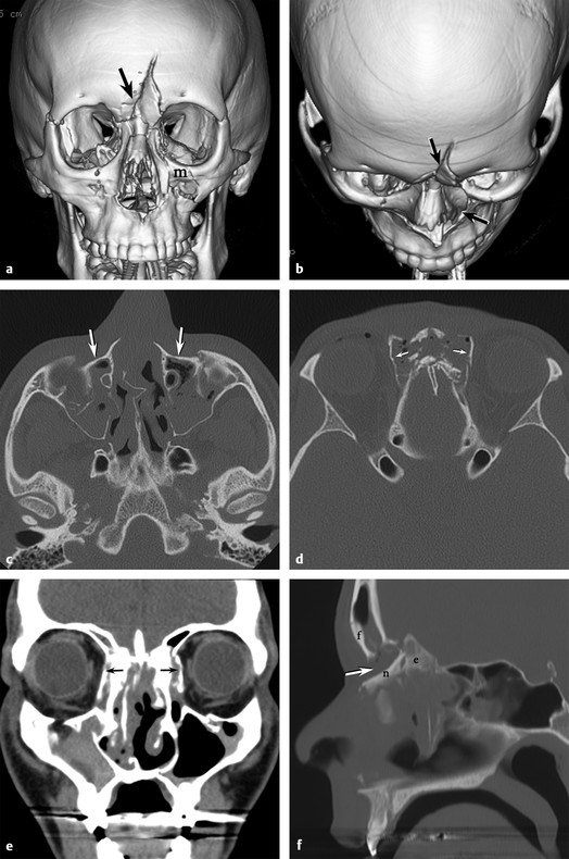
Fig. 11.15 Nasal-orbito-ethmoid fractures. (a) Three dimensional (3D) computed tomographic (CT) reformat anterposterior view shows a depressed midline frontal fracture (arrow) extending into the nasal bones and left medial maxilla (m). (b) 3D CT reformat superior-inferior view shows the posterior displacement of the frontal bone and nasal arch fractures (arrows). (c) Axial CT shows preservation of the zygomatic arches with posterior displacement (arrows) of the midface maxillary frontal processes. (d) Axial CT shows the crumple zone of the nasoethmoid complex with lateral displacement of the lamina papyracea (arrows) on both sides. (e) Coronal CT demonstrates lateral displacement (arrows) of the lamina papyracea with hypertelerism. (f) Sagittal CT clearly shows 1 cm of posterior displacement (arrow) of the nasal (n) and ethmoid (e) structures relative to the frontal (f) bone.
11.4.7 Medial Buttress Fracture
A medial buttress fracture can be thought of as a unilateral subtype of the naso-orbito-ethmoid. This medial buttress comprises the medial maxilla, frontal process of the maxilla, and nasal bone. This fracture often has its superior extent at the frontal-maxillary suture at the glabella (▶ Fig. 11.16). Like the NOE fracture, the medial buttress fracture can obstruct the nasolacrimal duct and cause epiphora.
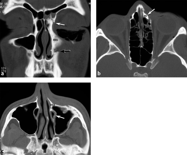
Fig. 11.16 Medial buttress fracture. (a) Coronal computed tomography (CT) shows medial rotation of the left medial maxilla (ms, medial strut) at the nasofrontal suture (white arrow) superiorly and the anterior maxilla fracture zone (black arrow) inferiorly. Subcutaneous emphysema in the left lower eyelid. (b) Axial CT shows posteromedial displacement (arrow) of the frontal process of maxilla (m) superiorly. (c) Axial CT demonstrates medial rotation of the medial strut (ms) and compression of the nasolacrimal duct (arrow) inferiorly.
11.4.8 Orbital Apex Fracture and Optic Canal Fracture
Fractures of the anterior skull base and central skull base may include the orbital apex. These fractures may include the sagittal plane posterior extension of the frontal bone and NOE fractures, coronal plane fractures extending from one or both longitudinal temporal fractures that extend into the sphenoid bone, and complex fractures of the greater sphenoid wing. Fracture fragments and orbital apex hematoma may compromise the optic nerve (▶ Fig. 11.17a,b).
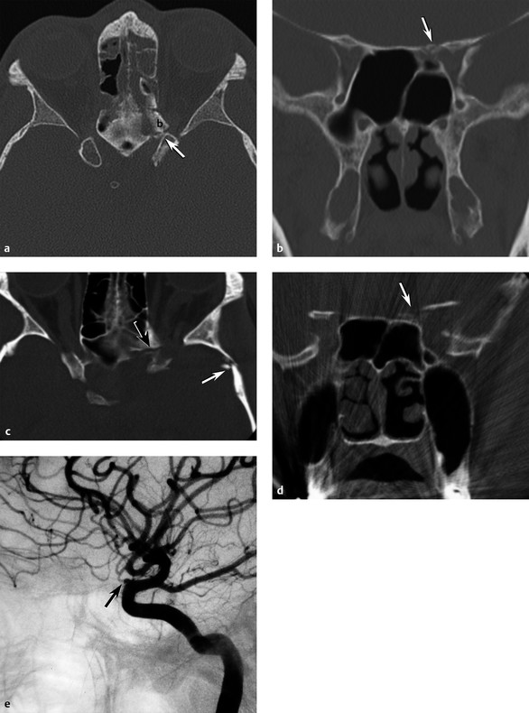
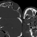
Fig. 11.17 Optic canal fractures. (a) Axial computed tomography (CT) shows an oblique fracture at the sphenoethmoid junction and a displaced fracture fragment (b) in the left optic canal (arrow). (b) Coronal CT same patient with fracture through the sphenoid lesser wing and medial-superior wall (arrow) of the left optic canal. (c) Axial CT in a different patient with complete visual loss in the left eye after a motor-vehicle collision; CT shows fractures laterally through the left greater sphenoid wing (white arrow) extending medially into the lesser sphenoid wing (black arrow) structures of the anterior clinoid and left optic canal. (d) Coronal CT demonstrates disruption of the left anterior clinoid and bone fragments (arrow) in the left optic canal. (e) Lateral left internal carotid artery angiogram shows complete cutoff of the left ophthalmic artery (arrow).
An optic canal fracture is a subtype of the orbital apex fracture, which specifically involves the body of the sphenoid bone at the confluence of the lesser sphenoid wing and anterior clinoid process, which form the margins of the optic canal. With the optic nerve and ophthalmic artery passing through the optic canal, displaced fragments and shearing forces may injure the tightly confined optic nerve resulting in visual loss (▶ Fig. 11.17c,d,e).
11.5 Injury to the Orbital Soft Tissues
The soft tissues of the orbit may be injured in both blunt and penetrating facial trauma. Assessment of the optic pathway for injury or foreign body is critical and should include the eye and optic nerve. Hematoma and edema may affect the preseptal soft tissues, retro-ocular fat, and subperiosteal space. These tissues can be readily assessed using volume CT techniques.
11.5.1 Mass Effect
Acute mass effect in the orbit may manifest as compression of one side of the globe, axial proptosis, or off-axis displacement of the globe. Orbital soft tissue mass effect is more commonly unilateral, but it can be bilateral.
Proptosis can be assessed by the globe position relative to the orbital rim. At the midglobe level on an axial CT slice, the interzygomatic line (a line drawn from one frontozygomatic suture or lateral orbital rim to the contralateral lateral orbital rim) will normally show about a third of the posterior globe behind the interzygomatic line (▶ Fig. 11.18a). The inner-to-outer canthal line is often more challenging to use because the medial bony landmark of the frontal process of the maxilla is often harder to define (▶ Fig. 11.18b). In a normal orbit, about half of the globe should lie posterior to this line. Relative proptosis can then be measured, especially if only one eye or orbit is injured. Difficulty occurs in ZMC, Le Fort III, and NOE fractures, which disrupt and displace bony landmarks, making the drawing of these lines problematic.
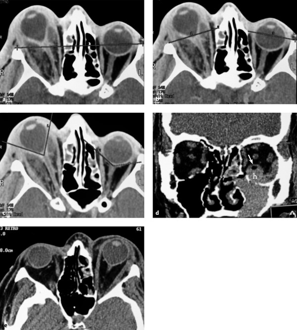
Fig. 11.18 Signs of orbital mass effect. (a) Patient with right orbital abscess and proptosis demonstrating the interzygomatic line. (b) Demonstration of the inner-to-outer canthal lines. (c) Globe tenting on the right with a posterior globe angle of 85 degrees compared with a normal left posterior globe angle of 135 degrees. (d) Coronal computed tomography (CT) shows a different patient with an inferior blowout fracture with subperiosteal hematoma (h) elevating the inferior rectus muscle (arrow). (e) Axial CT from the same patient demonstrates proptosis and moderate acute globe tenting.
Globe tenting is another measure of acute orbital tension associated with axial globe proptosis. As the globe is pushed anteriorly, the optic nerve begins to straighten and stretch, tethering the posterior globe margin at the optic nerve head, causing a conical deformation of the posterior globe (▶ Fig. 11.18c). When an angle is measured subtending the tethered posterior globe margin at the optic nerve head, an angle less than 120 degrees (▶ Fig. 11.18d,e) may correlate with a high incidence of afferent pupillary defect.1 Urgent decompression of the proptosis and globe tenting are needed to preserve vision.
Related posts:
Stay updated, free articles. Join our Telegram channel

Full access? Get Clinical Tree


