2 Ultrasound and imaging
NATURE OF ULTRASOUND
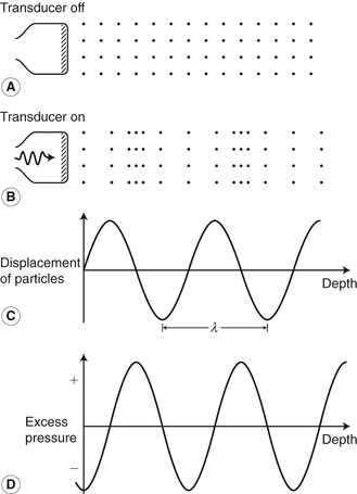
Ultrasound, as the name implies, is high-frequency sound. Sound waves travel through a medium by causing local displacement of particles within the medium; however, there is no overall movement of the medium. Unlike light, sound cannot travel through a vacuum as sound waves need a supporting medium. Consider a piece of string held at both ends: with one end briefly shaken, the vibration caused will travel along the string and in so doing transmit energy from one end of the string to the other. This is known as a transverse wave, as the movement of the string is at right angles to the direction in which the wave has moved. Ultrasound is a longitudinal wave, as the displacement of the particles within the medium is in the same direction as that in which the wave is travelling. Figure 2.1 shows a medium with particles distributed evenly within it. The position of the particles within the medium will change as a sound wave passes through it, causing local periodic displacement of these particles (Fig. 2.1B). The size, or amplitude, of these displacements is shown in Figure 2.1C. As the particles move within the medium, local increases and decreases in pressure are generated (Fig. 2.1D).
Wavelength and frequency
Ultrasound is usually described by its frequency, which is related to the length of the wave produced. The wavelength of a sound wave is the distance between consecutive points where the size and direction of the displacement are identical and the direction in which the particles are travelling is the same. The wavelength is represented by the symbol λ and is shown in Figure 2.1C. The time taken for the wave to move forwards through the medium by one wavelength is known as the period (τ). The frequency, f, is the number of cycles of displacements passing through a point in the medium during 1 second (s) and is given by:
 (2.1)
(2.1)Speed of ultrasound
 (2.2)
(2.2)The speed of sound through a material depends both on the density and the compressibility of the material. The more dense and the more compressible the material, the slower the wave will travel through it. The speed of sound is different for the various tissues in the body (Table 2.1). Knowledge of the speed of sound is needed to determine how far an ultrasound wave has traveled. This is required in both imaging and pulsed Doppler (as will be seen later), but ultrasound systems usually make an estimate by assuming that the speed of sound is the same in all tissues: 1540 m/s. This can lead to small errors in the estimated distance traveled because of the variations in the speed of sound in different tissues.
Table 2.1 Speed of sound in different tissues
| MEDIUM | SPEED OF SOUND (m/s) |
|---|---|
| Air | 330 |
| Water (20°C) | 1480 |
| Fat | 1450 |
| Blood | 1570 |
| Muscle | 1580 |
| Bone | 3500 |
| Soft tissue (average) | 1540 |
GENERATION OF ULTRASOUND WAVES
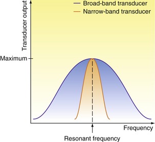
The term ‘transducer’ simply means a device that converts one form of energy into another. In the case of an ultrasound transducer, this conversion is from electrical energy to mechanical vibration. The piezoelectric effect is the method by which most medical ultrasound is generated. Piezoelectric materials will vibrate mechanically when a varying voltage is applied across them. The frequency of the voltage applied will affect the frequency with which the material vibrates. The thickness of the piezoelectric element will determine the frequency at which the element will vibrate most efficiently; this is known as the resonant frequency of the transducer. The speed of sound within the element will depend on the material from which it is made. A resonant frequency occurs when the thickness of the element is half the wavelength of the sound wave generated within it. At this frequency, the reflected waves from the front and back faces of the element act to reinforce each other, so increasing the size of the vibration produced. When an appropriate coupling medium is used (e.g., ultrasound gel), this vibration will be transmitted into a surrounding medium, such as the body. The named frequency of a transducer is its resonant frequency. This is not to say that the transducer will not function at a different frequency, but it will be much less efficient at those frequencies. Most modern imaging transducers are designed as broad-band transducers, meaning that they will function efficiently over a wide range of frequencies, and these are usually labeled with the frequency range over which they operate (e.g., 3–9 MHz). Figure 2.2 shows how the transducer output of narrow-band and broad-band transducers varies with the frequency of the excitation voltage. A broad-band transducer is more efficient over a wider range of frequencies than a narrow-band transducer. Ultrasound transducers also use the piezoelectric effect to convert the returning ultrasound vibrations back into electrical signals. These signals can then be amplified, analyzed, and displayed to provide anatomical images together with flow information.
 (2.3)
(2.3)Frequency content of pulses
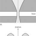
Typically, the pulses used in imaging ultrasound are very short and will only contain 1–3 cycles in order that reflections from boundaries that are close together can be easily separated. Pulsed Doppler signals are longer and contain several cycles. In fact, a pulse is made up not of a single frequency but of a range of frequencies of different amplitudes. Different-shaped pulses will have different frequency contents. Figure 2.3 illustrates how a signal can be made up of the sum of several different frequencies. The frequency content of a signal can be displayed on a graph, such as those shown in Figure 2.4 (right panels). This is known as a frequency spectrum and displays the frequencies present within the signal against the relative amplitudes of these frequencies. Figure 2.4A provides an example of a continuous signal consisting of a single frequency. As only one frequency is present in the signal, the frequency spectrum displays a single line at that frequency (Fig. 2.4B). Figure 2.4C, E, and G give examples of three differently shaped signals along with their frequency spectra (Fig. 2.4D, F, and H), showing the range of frequencies present in each of the different signals. As ultrasound imaging uses pulsed ultrasound, the transducer is not transmitting a single frequency but a range of frequencies.
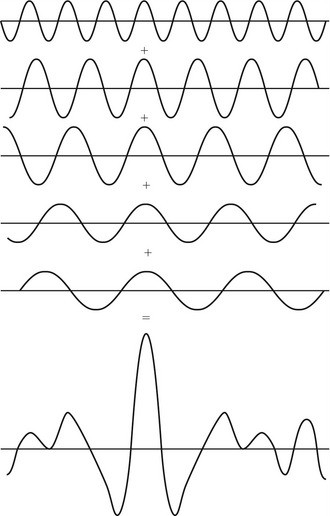
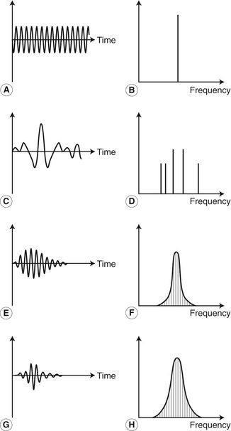
Figure 2.4 Four different signals (amplitude plotted against time) and their corresponding frequency spectra (power plotted against frequency). (A, B) For a continuous single frequency. (C, D) Signal shown in Figure 2.3. (E, F) A long pulse. (G, H) A short pulse. The shorter the pulse, the greater the range of frequencies within the pulse.
(After Fish 1990, with permission.)
INTERACTION OF ULTRASOUND WITH SURFACES
The creation of an ultrasound image depends on the way in which ultrasound energy interacts with the tissue as it passes through the body. When an ultrasound wave meets a large smooth interface between two different media, some of the energy will be reflected back, and this is known as specular reflection. The relative proportions of the energy reflected and transmitted depend on the change in the acoustic impedance between the two materials (Fig. 2.5). The acoustic impedance of a medium is the impedance (similar to resistance) the material offers against the passage of the sound wave through it and depends on the density and compressibility of the medium. The greater the change in the acoustic impedance across a boundary, the greater the proportion of the ultrasound that is reflected. There is, for example, a large difference in acoustic impedance between soft tissue and bone, or between soft tissue and air, and such interfaces will produce large reflections. This is the reason why ultrasound cannot be used to image beyond lung or bone, except in limited situations, as only a small proportion of the ultrasound is transmitted. It is also the reason for the loss of both imaging and Doppler information beyond calcified arterial walls, bone (Fig. 10.13), and bowel gas, leading to an acoustic shadow beyond. Table 2.2 shows the ratio of the reflected to incident wave amplitude for a range of reflecting interfaces.
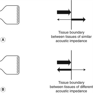
Table 2.2 The ratio of reflected to incident wave amplitude for an ultrasound beam perpendicular to different reflecting interfaces
| REFLECTING INTERFACE | RATIO OF REFLECTED TO INCIDENT WAVE AMPLITUDE |
|---|---|
| Muscle/blood | 0.03 |
| Soft tissue/water | 0.05 |
| Fat/muscle | 0.10 |
| Bone/muscle | 0.64 |
| Soft tissue/air | 0.9995 |
(after McDicken 1981, with permission)
The path along which the reflected ultrasound travels will also affect the amplitude of the signal detected by the transducer. If the beam is perpendicular to the interface, the reflected ultrasound will travel back along the same path to the transducer. If, however, the beam intercepts the interface at an angle of less than 90°, then the beam will be reflected along a different path. Figure 2.6 shows that the angle of incidence (θi) is the same as the angle of reflection (θr
Related posts:
Stay updated, free articles. Join our Telegram channel

Full access? Get Clinical Tree


