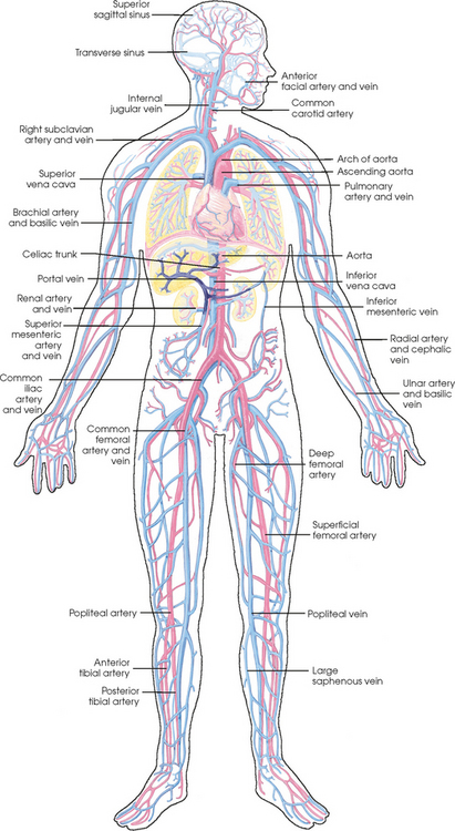
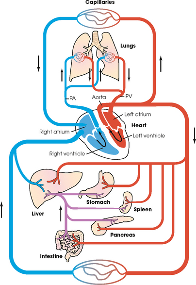
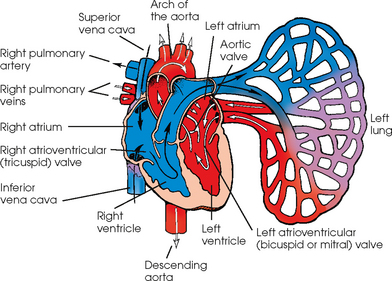
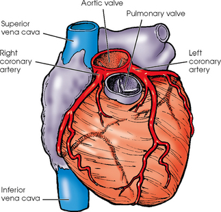
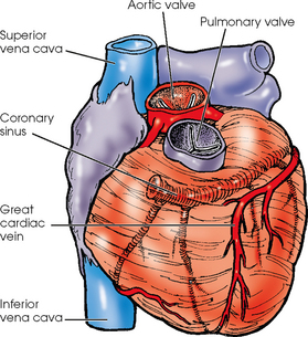
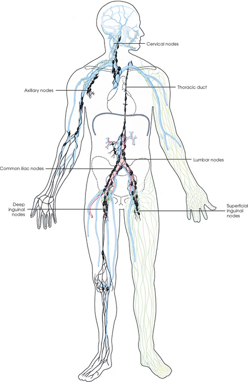
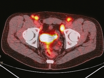
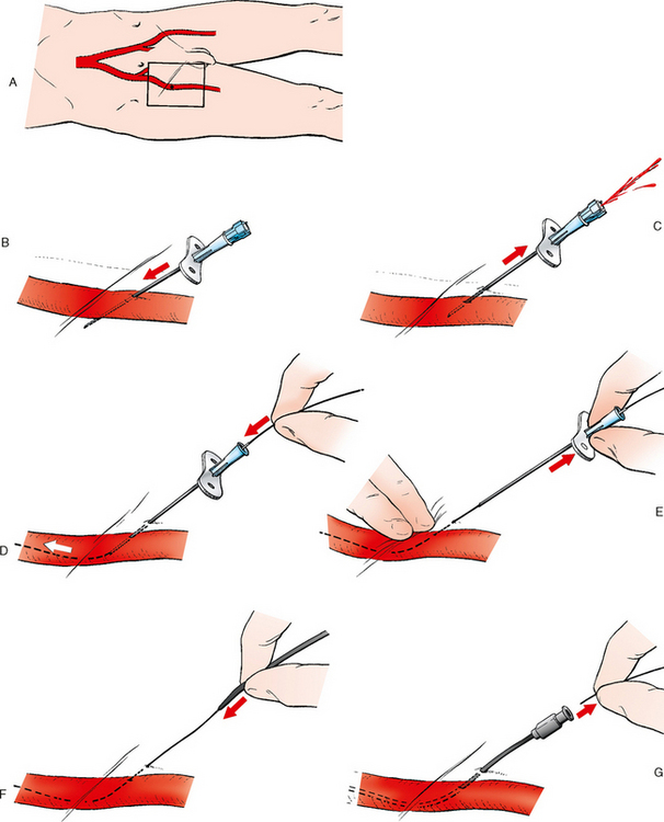
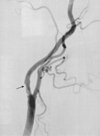
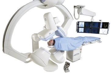
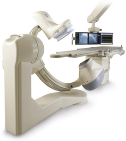
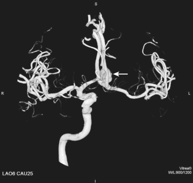
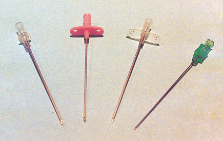
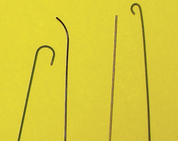
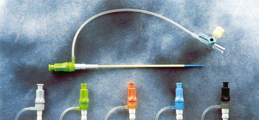
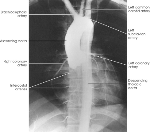
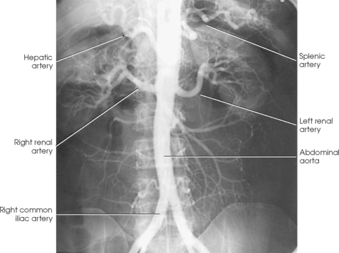
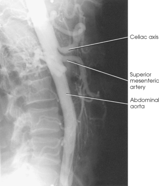
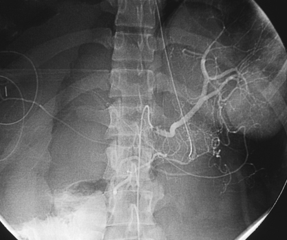
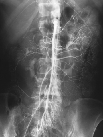
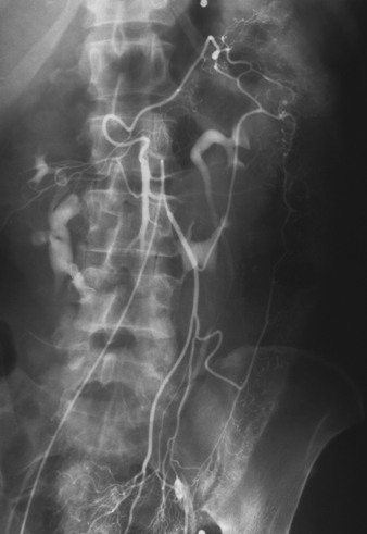
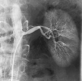
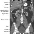
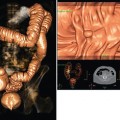
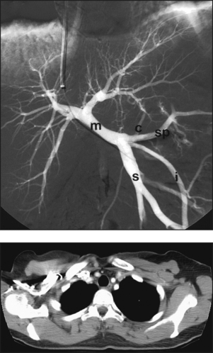
25 Percutaneous transluminal angioplasty and stenting Abdominal aortic aneurysm endografts Inferior vena cava filter placement Transjugular intrahepatic portosystemic shunt The circulatory system* has two complex systems of intimately associated vessels. Through these vessels, fluid is transported throughout the body in a continuous, unidirectional flow. The major portion of the circulatory system transports blood and is called the blood-vascular system (Fig. 25-1). The minor portion, called the lymphatic system, collects fluid from the tissue spaces. This fluid is filtered throughout the lymphatic system, which conveys it back to the blood-vascular system. The fluid conveyed by the lymphatic system is called lymph. Together, the blood-vascular and lymphatic systems carry oxygen and nutritive material to the tissues. They also collect and transport carbon dioxide (CO2) and other waste products of metabolism from the tissues to the organs of excretion: the skin, lungs, liver, and kidneys. Two circuits of blood vessels branch out of the heart (Fig. 25-2). The first circuit is the arterial circuit or the systemic circulation, which carries oxygenated blood to the organs and tissues. Every organ has its own vascular circuit that arises from the trunk artery and leads back to the trunk vein for return to the heart. The systemic arteries branch out, treelike, from the aorta to all parts of the body. The arteries are usually named according to their location. The systemic veins usually lie parallel to their respective arteries and are given the same names. The systemic veins are arranged in a superficial set and in a deep set with which the superficial veins communicate; both sets converge at a common trunk vein. The systemic veins end in two large vessels opening into the heart: The superior vena cava leads from the portion of the body above the diaphragm, and the inferior vena cava leads from below the level of the diaphragm. The atria function as receiving chambers. The superior and inferior venae cavae empty into the right atrium (Fig. 25-3); the two right and left pulmonary veins empty into the left atrium. The ventricles function as distributing chambers. The right side of the heart handles the venous, or deoxygenated, blood, and the left side handles the arterial, or oxygenated, blood. The left ventricle pumps oxygenated blood through the aortic valve into the aorta and the systemic circulation. The three major portions of the aorta are the ascending aorta, the aortic arch, and the descending aorta. The right ventricle pumps deoxygenated blood through the pulmonary valve into the pulmonary trunk and the pulmonary circulation. Blood is supplied to the myocardium by the right and left coronary arteries. These vessels arise in the aortic sinus immediately superior to the aortic valve (Fig. 25-4). Most of the cardiac veins drain into the coronary sinus on the posterior aspect of the heart, and this sinus drains into the right atrium (Fig. 25-5). The velocity of blood circulation varies with the rate and intensity of the heartbeat. Velocity also varies in the different portions of the circulatory system based on distance from the heart. The speed of blood flow is highest in the large arteries arising at or near the heart because these vessels receive the full force of each wave of blood pumped out of the heart. The arterial walls expand with the pressure from each wave. The walls then rhythmically recoil, gradually diminishing the pressure of the advancing wave from point to point, until the flow of blood is normally reduced to a steady, nonpulsating stream through the capillaries and veins. The beat, or contraction and expansion of an artery, may be felt with the fingers at several points and is called the pulse. The lymphatic system consists of an elaborate arrangement of closed vessels that collect fluid from the tissue spaces and transport it to the blood-vascular system. Almost all lymphatic vessels are arranged in two sets: (1) a superficial set that lies immediately under the skin and accompanies the superficial veins and (2) a deep set that accompanies the deep blood vessels and with which the superficial lymphatics communicate (Fig. 25-6). The lymphatic system lacks a pumping mechanism such as the heart of the bloodvascular system. The lymphatic vessels are richly supplied with valves to prevent backflow, and the movement of the lymph through the system is believed to be maintained largely by extrinsic pressure from the surrounding organs and muscles. Lymphography is seldom performed in current practice because of the superior imaging capabilities of newer modalities such as magnetic resonance imaging (MRI) and computed tomography (CT) (Fig. 25-7). At present, it is primarily used to assess the clinical extent of lymphomas or to stage radiation treatment. Lymphography may also be indicated in patients who have clinical evidence of obstruction or other impairment of the lymphatic system. A more detailed description of lymphography is provided in previous editions of this text. Limitations still existed. Until the 1950s, contrast medium was most commonly injected through a needle that punctured the vessel or through a ureteral catheter that passed into the body through a surgically exposed peripheral vessel. In 1952, shortly after the development of a flexible thin-walled catheter, Seldinger announced a percutaneous method of catheter introduction. The Seldinger technique eliminated the surgical risk, which exposed the vessel and tissues (see Fig. 25-16). Some DSA equipment allows the table or the image intensifier (II) or flat panel detector system to be moved during acquisition. The movement is permitted to “follow” the flow of iodine contrast material as it passes through the arteries. Sometimes called the “bolus chase” or “DSA stepping” method, this technique is particularly useful for evaluating the arteries in the pelvis and lower limb. Previously, several separate imaging sequences would be performed with the II or flat panel positioned in a different location for each sequence, but this method required an injection of iodine contrast material for each sequence. The bolus chase method requires only one injection of iodine, and the imaging sequence follows (or “chases”) the iodine as it flows down the limb. The imaging sequence may be preceded or followed by a duplicate sequence without iodine injection to enable subtraction. Occasionally, this method may need to be repeated because the contrast medium in one leg may flow faster than in the other. During the imaging procedure, the subtraction images appear on the display monitor (Fig. 25-8). Often a preliminary diagnosis can be made at this point or as the images are reviewed immediately after each exposure sequence. A formal reading session occurs after the patient study has been completed; the final diagnosis is made at that time. Imaging systems may be used either singly or in combination at right angles to obtain simultaneous frontal and lateral images of the vascular system under investigation with one injection of contrast medium. This arrangement of units is called a biplane imaging system (Fig. 25-9). When two image receptors operate together for simultaneous biplane imaging, exposures in both planes cannot be made at the same moment because scatter radiation would fog the opposite plane image. Yet biplane imagers must cycle exactly together so that synchronization can be electronically controlled. It is necessary to alternate the exposures in the two planes. The x-ray tubes in a biplane system must fire alternately to prevent exposure of the opposite II. In addition, the II that is not being exposed is “blanked” or is powered off for an instant so as not to receive any input from the opposite exposure. The difference in the alternating exposures is about 3 msec. A comprehensive angiography suite contains a great amount of equipment other than radiologic devices. Monitoring systems record patient electrocardiogram (ECG) data, blood pressure readings, and pulse oximetry. Emergency equipment includes resuscitation equipment (e.g., a defibrillator for the heart) and anesthesia apparatus. The cardiovascular and interventional technologist (CIT) must be familiar with the use of each piece of equipment (Fig. 25-10). The latest diagnostic tool is threedimensional angiography. To acquire a three-dimensional model of a vascular structure, a C-arm is rotated around the region of interest (ROI) at speeds up to 60 degrees per second. The C-arm makes a preliminary sweep while mask images are acquired. Images are acquired at 7.5 to 30 frames per second. The C-arm returns to its initial position, and a second sweep is initiated. Just before the second sweep, contrast medium is injected to opacify the vascular anatomy. The second sweep matches mask images from the first sweep, producing a rotational subtracted DSA sequence. The DSA sequence is sent to a three-dimensional rendering computer where a three-dimensional model is constructed. This model provides an image that can be manipulated and analyzed. It has proved to be a valuable tool for interventional approaches and for evaluation before surgery. Various methods of vessel analysis are available with three-dimensional models. Aneurysm volume calculation, interior wall analysis, bone fusion, and device display all are possible (Figs. 25-11 and 25-12). Fig. 25-11 Three-dimensional angiography provides for reconstruction of the vessels and the skeletal anatomy. Vascular access needles are necessary when performing percutaneous procedures. Needle size is based on the external diameter of the needle and is assigned a gauge size. To allow for appropriate guidewire matching, the internal diameter of the needle must be known. Vascular access needles come in different types, sizes, and lengths. The most commonly used access needle for adult cardiovascular procedures is an 18-gauge needle that is 2.75 inches (7 cm) long. This particular needle is compatible with a 0.035-inch guidewire, which is the most frequently used guidewire in cardiovascular procedures. Appropriate needle size is predicated on the type or size of guidewire needed, the size of the patient, and the targeted entry vessel. To decrease the chances of vascular complications, the smallest gauge needle that meets the above-mentioned criteria is used for vascular access. Access needles for pediatric patients come in smaller gauge sizes with shorter lengths (Fig. 25-13). More recently, plastic alloy guidewires consisting of a hydrophilic plastic polymer coating have been introduced. These new wires provide a very smooth outer coating, with a pliable tip, and exhibit a high degree of torque or maneuverability (Fig. 25-14). Similar to vascular catheters, introducer sheaths come in various sizes and lengths. Typically, most introducer sheaths range in length from 4 to 35 inches (10 to 90 cm). Catheters are measured by their outside diameters and expressed in units of French size (Fr), and introducer sheaths are named according to the French size catheter they can accommodate. To accomplish this, the outer diameters of introducer sheaths are 1.5 to 2 Fr sizes larger than the catheter they can accept. A 5-Fr introducer has an outer diameter of nearly 7 Fr and accepts a 5-Fr catheter (Fig. 25-15). 1. The risk of extravasation is reduced. 2. Most body parts can be reached for selective injection. 3. The patient can be positioned as needed. 4. The catheter can be safely left in the body while radiographs are being examined. The most widely used catheterization method is the Seldinger technique.1 Seldinger described the method as puncture of both walls of the vessel (the anterior and posterior walls). The modified Seldinger technique allows for puncture of the anterior wall only and has become the preferred method. The steps of the technique are described in Fig. 25-16. The procedure is performed under sterile conditions. The catheterization site is suitably cleaned and surgically draped. The patient is given local anesthesia at the catheterization site. With this percutaneous technique, the arteriotomy or venotomy is no larger than the catheter itself, so hemorrhage is minimized. Patients can usually resume normal activity within 24 hours after the examination. In some diagnostic angiographic studies, the procedure can be performed in the early morning, and the patient may be discharged later that same day. Most often, an uncomplicated interventional procedure may be performed, and the patient recovers in an ambulatory care area and is discharged home usually within 24 hours. The risk of infection is less than in surgical procedures because the vessel and tissues are not exposed. Catheters are produced in various forms, each with a particular advantage in shape, maneuverability or torque, and maximum injection rate (Fig. 25-17). Angiographic catheters are made of pliable plastic that allows them to straighten for insertion over the guidewire, also called a wire guide. They normally resume their original shape after the guidewire is withdrawn. It usually requires manipulation from the angiographer to resume its original shape, however. Catheters with a predetermined design or shape are maneuvered into the origins of vessels for selective injections. They may have only an end hole, or they may have multiple side holes. Some catheters have multiple side holes to facilitate high injection rates but are used only in large vascular structures for flush injections. A pigtail catheter is a special multiple–side hole catheter that allows higher volumes of contrast medium to be injected with less whiplash effect, causing less damage to the vessel being injected. • Check the angiographic equipment and all working parts of the equipment, and adjust the controls for the exposure technique to be employed. • Have restraining bands available for application in combative patients. • Adapt immobilization of the head (by suitable strapping) to the type of equipment employed. • Ensure patient information is entered correctly on aquisition equipment. • For lateral projections, move the patient’s arms superiorly so that they do not appear in the image. • For best results, increase lateral SID, usually to 60 inches (152 cm), so that magnification is reduced. • If biplane equipment is unavailable, use a single-plane 45-degree right posterior oblique (RPO) or left anterior oblique (LAO) body position, which often produces an adequate study of the aorta. • For all projections, direct the perpendicular central ray to the center of the chest at the level of T7. The entire thoracic aorta should be visualized, including the proximal brachiocephalic, carotid, and subclavian vessels. The contrast medium is injected at rates ranging from 25 to 35 mL/sec for a total volume of 50 to 70 mL. • Make the exposure at the end of suspended inspiration (Fig. 25-18). • For the lateral projection, move the patient’s arms superiorly so that they are out of the image field. • Usually, collimate the field in the AP aspect of the lateral projection. • Direct the perpendicular central ray at the level of L2 so that the aorta is visualized from the diaphragm to the aortic bifurcation. The AP projection shows best the renal artery origins, the aortic bifurcation, and the course and general condition of all abdominal visceral branches. The lateral projection best shows the origins of the celiac and superior mesenteric arteries because these vessels arise from the anterior abdominal aorta. • Make the exposure at the end of suspended expiration (Figs. 25-19 and 25-20). Under fluoroscopic control, a catheter is passed from a peripheral vein through the vena cava and right side of the heart and into the pulmonary arteries. This technique is usually employed for a selective injection, and the examination is primarily performed for the evaluation of pulmonary embolic disease (Fig. 25-21). Pulmonary angiography has widely been replaced with pulmonary CT angiography because it provides superior imaging. Abdominal visceral arteriographic studies (Fig. 25-22) are usually performed to visualize tumor vascularity or to rule out atherosclerotic disease, thrombosis, occlusion, and bleeding. An appropriately shaped catheter is introduced, usually from a transfemoral artery puncture, and advanced into the orifice of the desired artery. The CIT observes the following steps: • Perform all selective studies initially with the patient in the supine position for single-plane frontal images. • Direct the central ray perpendicular to the image receptor. • If necessary, use oblique projections to improve visualization or avoid superimposition of vessels. • For all abdominal visceral studies, obtain angiograms during suspended expiration. Selective abdominal visceral arteriograms are described in the following sections. • To visualize the IMA best, use a 15-degree RAO or LPO position that places the descending colon and rectum at the left and inferior margins of the image (Fig. 25-27). The imaging is the same as that for the SMA. • A renal flush aortogram may be accomplished by injecting 25 mL/sec for a 40-mL total volume of contrast medium through a multiple–side hole catheter positioned in the aorta at the level of the renal arteries. A representative selective injection is 8 mL/sec for a 12-mL total volume. • For a right renal arteriogram, position the patient so that the central ray enters at the level of L2 midway between the center of the spine and the patient’s right side. • For a selective left renal arteriogram, position the patient so that the central ray usually enters at the level of L1 midway between the center of the spine and the patient’s left side (Fig. 25-28). • Place the patient in the supine position for either a single-plane AP or PA projection or biplane projections. Move the patient’s arms out of the field of view. • Obtain lateral projections at increased SID, if possible, to reduce magnification. • Remember that collimation to the long axis of the vena cava improves image quality but may prevent visualization of peripheral or collateral veins. Venography of the superior vena cava is performed primarily to rule out the existence of thrombus or the occlusion of the superior vena cava. The contrast medium may be injected through a needle or an angiographic catheter introduced into a vein in an antecubital fossa, although superior opacification results from injection through a catheter positioned in the axillary or subclavian vein. Radiographs should include the opacified subclavian vein, brachiocephalic vein, superior vena cava, and right atrium (Fig. 25-29). Venography of the inferior vena cava is performed primarily to identify the location of the renal veins for placement of an inferior vena cava filter. The contrast medium is injected through a multiple–side hole catheter inserted through the femoral vein and positioned in the common iliac vein or the inferior aspect of the inferior vena cava (Fig. 25-30). The visceral veins are often visualized by extending the imaging program of the corresponding visceral artery injection. The veins that drain the small bowel are normally visualized by extending the imaging program of a superior mesenteric arteriogram. Portal venography (Fig. 25-31) can be performed by injecting the portal vein directly from a percutaneous approach, but it is usually accomplished by late-phase imaging of a splenic artery injection or SMA injection.
VASCULAR, CARDIAC, AND INTERVENTIONAL RADIOGRAPHY
Circulatory System
Blood-Vascular System
Lymphatic System
Historical Development
Digital Subtraction Angiographic Procedures
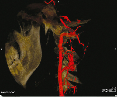
THREE-DIMENSIONAL INTRAARTERIAL ANGIOGRAPHY
Angiographic Supplies and Equipment
GUIDEWIRES
INTRODUCER SHEATHS
CATHETERIZATION
Preparation of Examining Room
Thoracic Aortography
Abdominal Aortography
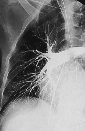
Pulmonary Arteriography
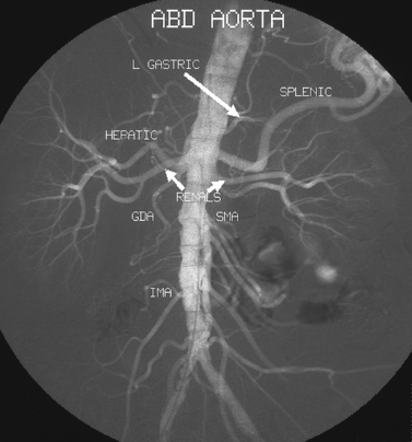
Selective Abdominal Visceral Arteriography
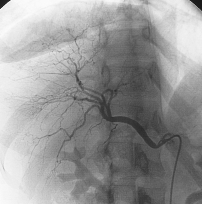
SPLENIC ARTERIOGRAM
INFERIOR MESENTERIC ARTERIOGRAM
RENAL ARTERIOGRAM
Central Venography
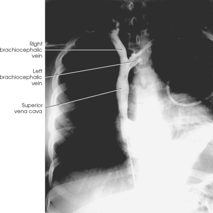
SUPERIOR VENACAVOGRAM
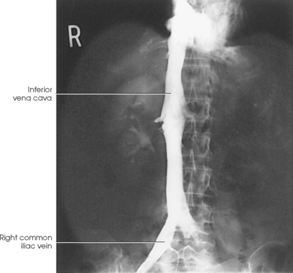
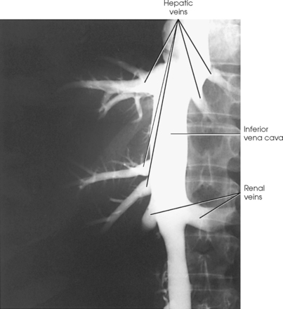
INFERIOR VENACAVOGRAM
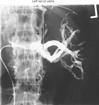
Selective Visceral Venography
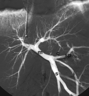
HEPATIC VENOGRAM
VASCULAR, CARDIAC, AND INTERVENTIONAL RADIOGRAPHY