X-Ray Production, Tubes, and Generators
6.0 INTRODUCTION
This chapter describes the x-ray production process, characteristics of the x-ray beam, x-ray tube design x-ray generator components, and factors that affect exposure and exposure rate.
6.1 PRODUCTION OF X-RAYS
1. Bremsstrahlung spectrum
a. Conversion of kinetic energy of electrons into electromagnetic radiation (x-rays).
b. An environment and requirements to produce x-rays are shown in Figure 6-1.
c. Voltage applied to the cathode and anode accelerates electrons to a kinetic energy = voltage.
d. Electrons interact with other electrons to produce heat; electrons that interact with the nucleus of the tungsten target are decelerated through coulombic interactions as illustrated in Figure 6-2.
e. X-ray energies produced have a distribution described by the bremsstrahlung spectrum (Fig. 6-3).
f. Efficiency of x-ray production relative to heat production is typically less than 1%.
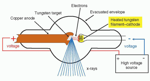
▪ FIGURE 6-1 Configuration of a simple x-ray tube with essential components listed. Electrons are generated by filament heating and thermionic emission. An external voltage accelerates the electrons to a kinetic energy equal to the potential difference (voltage) applied between the cathode and anode. Most electrons collide with target electrons and produce heat. A small fraction interact with the nucleus as shown in Figure 6-2.

▪ FIGURE 6-2 Incident electrons in close proximity to the nucleus of the target atom (e.g., tungsten, Z = 74) are attracted by the positive charge, decelerate, change direction, and momentum. The loss of momentum generates an x-ray photon through the conservation of energy. Electron no. 3 loses a small amount of energy and produces an x-ray with low energy; electron no. 2 in closer proximity to the nucleus loses more kinetic energy and produces a moderate x-ray energy; electron no. 3 loses all of its kinetic energy and produces the highest (peak) x-ray energy.

▪ FIGURE 6-3 The bremsstrahlung energy distribution for a 90-kV acceleration potential difference. The unfiltered bremsstrahlung spectrum (a) illustrates the greater probability of low-energy x-ray photon production that is inversely linear with energy up to the maximum energy of 90 keV. The filtered spectrum (b) shows the preferential attenuation of the lowest-energy x-ray photons. The vertical arrow (c) indicates the average energy of the spectrum, which is typically 1/3 to 1/2 the maximal energy, dependent on the amount of added filtration.
2. Characteristic X-rays
a. Incident electrons can interact with inner orbital electrons of the target atom.
b. Requires incident electron kinetic energy greater than binding energy of the electron in the atomic orbital.
c. Vacant shell via ejected electron from the target atom is immediately filled with electrons of lower binding energy, generating a “characteristic x-ray” of discrete energy equal to energy difference.
d. Electron binding energies of pertinent target materials are listed in Table 6-1.
e. Characteristic x-ray formation is illustrated in Figure 6-4 and resultant spectrum in Figure 6-5.
f. KA and KB characteristic x-ray energies result from adjacent shell and nonadjacent shell transitions.
TABLE 6-1 ELECTRON BINDING ENERGIES (keV) OF COMMON X-RAY TUBE TARGET MATERIALS | ||||||||||||||||
|---|---|---|---|---|---|---|---|---|---|---|---|---|---|---|---|---|
|
 ▪ FIGURE 6-4 Generation of a characteristic x-ray in a target atom: (1) The incident electron interacts with the K-shell electron. (2) The K-shell electron is removed (only if the energy of the incident electron is greater than the K-shell binding energy), leaving a vacancy in the K-shell. (3) An electron from the adjacent L-shell fills the vacancy. (4) A Kα characteristic x-ray photon is emitted with energy equal to the difference between the binding energies of the two shells, for example, 69.5 to 10.2 = 59.3 keV photon is emitted for tungsten target. |
 ▪ FIGURE 6-5 The filtered spectrum of bremsstrahlung and characteristic radiation from a tungsten target with a potential difference of 90 kV illustrates specific characteristic radiation energies from Kα and Kβ transitions. Filtration (the preferential removal of low-energy photons as they traverse matter) is discussed in Section 6.5. |
6.2 X-RAY TUBES
 ▪ FIGURE 6-6 A modern x-ray tube cross-sectional diagram with labeled components. The transformer oil is used as an insulator and heat conductor. Expansion bellows will activate a shut-off microswitch when the oil expands due to excessive heat. |
 ▪ FIGURE 6-7 The x-ray tube including the x-ray tube insert and partially cut-away housing. This housing has a lead shielding thickness of 2 mm. The tube port is facing downward (the lucent area between the cathode and anode in the picture). |
1. Cathode
a. The negative electrode comprised of electron emitters (filaments) and focusing cup; filament length provides small and large focal spot selections (Fig. 6-8).
b. Filament circuit activates filament to release electrons due to thermionic emission. A flow of electrons occurs when a voltage is applied; note difference of filament and tube current (Fig. 6-9).
c. Focusing cup shapes the electron distribution accelerated toward the anode; biased cups (more negative) can produce smaller distributions; grid biased focusing cups can stop flow (Fig. 6-10).

▪ FIGURE 6-8 The x-ray tube cathode structure consists of wound tungsten filament emitters positioned within the focusing cup. The filament circuit is activated to heat the selected filament, which emits electrons by thermionic emission at the filament surface.

▪ FIGURE 6-9 Relationship of tube current (number of electrons crossing the cathode—anode axis) to filament current for various applied tube kVs. For high filament current settings, a space charge cloud shields the electric field such that further increases in filament current do not increase the tube current.

▪ FIGURE 6-10 The focusing cup shapes the electron distribution when it is at the same voltage (“unbiased”) as the filament (left). Electrical Isolation of the focusing cup from the filament and application of a negative “biased” voltage (approximately -100 V) reduces the distribution of emerging electrons by increasing the repelling electric fields surrounding the filament (note the 0 V electric field potential line) and modifying the electron trajectories (middle). At the top are typical electron distributions incident on the target anode (the focal spot) for the unbiased and biased focusing cups. Application of -4,000 V on an electrically isolated focusing cup completely stops electron flow, even with high voltage applied on the tube; this is known as a grid-biased or “grid pulsed” tube (right).
2. Anode
a. The target electrode maintained at positive potential difference with respect to the cathode.
b. Tungsten (W), Z = 74, has a high melting point—used for most diagnostic systems.
c. Molybdenum (Mo), Z = 42, and rhodium (Rh), Z = 45, produce characteristic x-rays beneficial for mammography imaging (see Chapter 8).
3. Anode configurations
a. Stationary tungsten target embedded in a copper block (copper efficiently conducts heat) (Fig. 6-11)
(i) Used in low-power applications such as dental x-ray and handheld fluoro units
b. Rotating anode—higher heat-loading capability achieved by spreading out area of power deposition
(i) Requires induction motor (stator-rotor design) to rotate at 3,000 to 10,000 rpm (Fig. 6-12)

▪ FIGURE 6-11 The anode of a fixed anode x-ray tube consists of a tungsten target insert mounted in a copper block. Generated heat is removed from the tungsten target by conduction into the copper block. F. 6-12
4. Anode angle, field coverage, focal spot size
a. Anode angle: surface of the focal track to the perpendicular of the anode-cathode axis (Fig. 6-13).
b. Actual focal area length is foreshortened when projected down central axis according to the line focus principle: Effective focal length = Actual focal length × sin θ, where θ is the anode angle.
c. Focal spot effective size: width (determined by the focusing cup) × length (filament length).
d. Field coverage: dependent on anode angle and source to image distance (Fig. 6-14).
e. Effective focal spot varies in size along cathode-anode direction of the projection beam (Fig. 6-15).

▪ FIGURE 6-12 The anode of a rotating anode x-ray tube is a tungsten disk mounted on a bearing-supported rotor assembly (front view, top left; side view, top right). The rotor consists of a copper and iron laminated core and forms part of an induction motor. The other component is the stator, which exists outside of the insert, top right. A molybdenum stem reduces heat transfer to the rotor bearings (bottom). F. 6-13

▪ FIGURE 6-13 The anode (target) angle, θ, is defined as the angle of the anode surface in relation to the central axis (left). The focal track represents the total area over which heat is distributed during the x-ray exposure as the anode rotates. The actual focal area is characterized by a length and width (right). The focal spot length, as projected down the central axis, is foreshortened, according to the line focus principle (lower right). F. 6-14

▪ FIGURE 6-14 A. A large anode angle provides good field coverage at a given distance; however, the small actual focal area limits power loading. B. A large anode angle provides good field coverage, and high-power loading with a large focal area; however, geometric blurring occurs. C. A small anode angle limits field coverage at a given distance; however, a small focal spot is achieved with a large focal area for high-power loading. F. 6-15

▪ FIGURE 6-15 Variation of the projected focal spot size in the image occurs along the anodecathode direction. Focal spots are projected as a function of angle; toward the anode side, the focal spot length is shorter. F. 6-16
f. Measurement of focal spot size can be achieved by a pinhole camera, slit camera, star pattern, or resolution bar patterns (see Figs. 6-17, 6-18, and 6-19 in the textbook).
g. Nominal focal spot sizes are specified by the International Electrotechnical Commission (see Table 6-3 in the textbook).
5. Heel effect
a. Reduction in beam fluence on the anode side of the projected field caused by anode self-attenuation.
b. Heel effect is more prominent at short source-image distances (Fig. 6-16).
c. Orientation of the x-ray tube is important for equalizing transmitted x-ray fluence (Fig. 6-17).

▪ FIGURE 6-16 The heel effect is a loss of x-ray fluence on the anode side of the x-ray field. Electrons interacting at depth within the anode result in the “self-attenuation” of x-rays that have a trajectory toward the anode side of the field. F. 6-20

▪ FIGURE 6-17 Orientation of the x-ray tube is demonstrated for this posterior-anterior chest x-ray acquisition. When possible, the projected anode side of the field should be positioned over the thinner projections (lung apices) and the projected cathode side over the thicker projections (diaphragm) of the patient, so that the transmitted x-ray fluence variations to the detector are reduced. F. 6-21
6. Off-focal radiation
a. Incident electrons elastically rebound and impact the anode at areas outside of the focal spot.
b. Causes extra radiation dose, background signal, and geometric blurring (see textbook Fig. 6-22).
c. This effect is reduced with a grounded anode and hooded structure next to the anode focal area.
7. X-ray tube insert
a. Evacuated glass or metal enclosure containing the x-ray tube structures (see Figs. 6-6 and 6-7 above).
b. “Getter” circuit is used for trapping released outgassing of internal x-ray tube components.
c. Tube port made of beryllium (Be) is necessary for x-ray tubes employed for mammography.
8. X-ray tube housing
a. Provides mechanical, electrical, thermal, and radiation protection.
b. “Leakage x-rays” are reduced by lead shielding in the housing (typically 2 mm or more thick) to radiation levels no greater than 0.88 mGy air kerma (100 mR) per hour at 1 m from focal spot when using the highest kV at the highest continuous tube current (typically 125 to 150 kV and 3 to 5 mA).
c. Heat exchangers are used with high-power x-ray tubes by circulating the housing transformer oil.
9. X-ray tube filtration
a. Added metal filters (typically aluminum or copper sheets) placed near the tube port in the beam.
b. Tube total filtration includes inherent filtration of the insert material plus the added filters.
c. Compensation filters are used to modify the incident spatial fluence of the x-ray beam.
d. Wedge, trough, and bow-tie filters (the latter typically used for CT tubes) are used.
e. Filters chiefly modify the x-ray spectrum to selectively remove low-energy x-ray photons and lower radiation dose to the patient.Related posts:

Stay updated, free articles. Join our Telegram channel

Full access? Get Clinical Tree