(1)
National Institute for Physiological Sciences, National Institutes of Natural Sciences, Okazaki, Aichi, Japan
Abstract
Here, I review the principles and applications of phase-contrast electron microscopy using phase plates. First, I develop the principle of phase contrast based on a minimal model of microscopy, introducing a double Fourier-transform process to mathematically formulate the image formation. Next, I explain four phase-contrast (PC) schemes, defocus PC, Zernike PC, Hilbert differential contrast, and schlieren optics, as image-filtering processes in the context of the minimal model, with particular emphases on the Zernike PC and corresponding Zernike phase plates. Finally, I review applications of Zernike PC cryo-electron microscopy to biological systems such as protein molecules, virus particles, and cells, including single-particle analysis to delineate three-dimensional (3D) structures of protein and virus particles and cryo-electron tomography to reconstruct 3D images of complex protein systems and cells.
Key words
Phase contrastZernike phase contrastPhase plateCryo-electron microscopyElectron tomographyThree-dimensional reconstruction1 Introduction
Phase-contrast electron microscopy (EM) using a particular optical device, the phase plate, was first suggested over 60 years ago by the German electron microscopist H. Boersch [1]. Since then, a considerable number of research groups have developed phase plates upon his ideas, with the goal of achieving high-contrast imaging of organic materials, such as biological specimens, without heavy-metal staining. However, phase plates are prone to deteriorate due to charging induced by electron irradiation, and this phenomenon has long stood as an obstacle to progress in this field. Nonetheless, a recent report has described phase-contrast EM with remarkably high-contrast images and little image distortion [2].
The charging of phase plates is a fundamental problem that is difficult to solve, because there are many possible origins of electrostatic charge. We have had to identify and remove these multiple causes one by one. That required time-consuming testing of various technical parameters, e.g., conductivity of the amorphous carbon used for the phase plate, contact resistivity between the carbon and the supporting metal grid, and various kinds of dirt or other contaminants that sneak onto the phase-plate surface during fabrication. The biological applications of phase-contrast EM reported by my group over the last 10 years have cooperatively progressed in parallel with the efforts to cope with the trouble arising from phase-plate charging and to improve the phase-plate performance. In this article I will review phase-contrast EM by tracing the footsteps of improvements in the quality of phase plates and providing illustrations of phase-contrast images obtained from proteins, viruses, and cells.
2 Theoretical Framework
A target object thin enough to be observed with an electron microscope is transparent with respect to electron illumination, i.e., incident electrons completely penetrate through thin objects without loss of electrons. In other words, such objects act only to change the phase of the incident electron wave, but not its amplitude. Therefore, EM targets, which are traditionally called phase objects, require a phase-contrast scheme in order to be imaged. No matter what type of microscope is used, whether it is a light microscope (LM) or an electron microscope (EM), the process of visualization of phase objects can be described by using a minimal microscope that assumes only a coherent illumination by the incident beam, elastic scattering of incident waves, and phase disturbance by the target object. In a scalar theory of image formation, the spatially dependent phase disturbance to the incident wave, Ψ(r) (often termed an exit-wave function, where r represents the two-dimensional (2D) coordinates in real space), appears in the form of a 2D transparency function as e iθ(r). In electron microscopy, θ(r) may be related to the constituent atomic potential of the object.
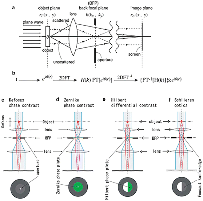
In wave optics, the formation of the corresponding image in a microscope can be schematically formulated as shown in Fig. 1, in which I introduce a mathematical interpretation of Abbe’s notion that the two successive diffraction processes through a two-lens system can be considered as a double Fourier-transform (FT) process [3]. Each of lens elements in the two-lens microscope behaves as a kind of FT operator, if it is properly installed. FT has the distinctive property that double FT of a function can restore the same function with an inversion of coordinates as
![$$ FT\left[ FT\left[\varPsi (r)\right]\right]=\varPsi \left(-r\right)\kern0.36em \left( FT\left[f\right]: FToperation\operatorname{}\,to\,\operatorname{}f\right) $$](/wp-content/uploads/2017/03/A300616_3_En_18_Chapter_Equ1.gif)

Fig. 1
Schematics describing the image-formation process in a minimal microscope. (a) A physical schematic for an imaging process under plane-wave illumination. (b) Corresponding mathematical formulation. 2D FT, two-dimensional Fourier transform; FT[ ], two-dimensional (2D) FT operation; H(k), spatial filter; and ⊗, 2D convolution. (c) A linear filter schematic for defocus phase contrast (DPC). (d) A linear filter schematic for Zernike phase contrast (ZPC). (e) A linear filter schematic for Hilbert phase contrast (HDC). (f) A linear filter schematic for schlieren optics (SO) or single-sideband imaging (SSI). Reproduced from Nagayama [4] Fig. 1, with the permission of Springer-Verlag
![$$ FT\left[ FT\left[\varPsi (r)\right]\right]=\varPsi \left(-r\right)\kern0.36em \left( FT\left[f\right]: FToperation\operatorname{}\,to\,\operatorname{}f\right) $$](/wp-content/uploads/2017/03/A300616_3_En_18_Chapter_Equ1.gif)
(1)
This means that we have an image, Ψ(−r) or Ψ(r) (when the coordinate inversion is ignored), that is exactly same as the wave function exiting from the object, Ψ(r).
In general, however, that kind of perfection cannot be fulfilled in a real microscopic system. Instead, optical anomalies such as lens aberrations or defocusing perturb the process. These perturbations can be formulated in image formation as the presence of a filter H(k) (k: 2D coordinates in Fourier space or frequency space) at the diffraction plane or back-focal-plane (BFP) of an objective lens (see Figs. 1a, b and also [4]). The filter H(k) modulates the wave function Ψ(r) and finally distorts otherwise perfect images. The phase plate can also be treated as a spatial filter that modulates the electron wave at the BFP in a spatial frequency-dependent manner.
With this minimal microscopic model, the principle of phase contrast for pure phase objects can be described as follows:

![$$ {\left| FT\left[H(k) FT\left[{\mathrm{e}}^{i\theta (r)}\right]\right]\right|}^2=\left|\left\{ FT\left[H(k)\right]\right\}\otimes {\mathrm{e}}^{i\theta (r)}\right|{}^2\ne 1 $$](/wp-content/uploads/2017/03/A300616_3_En_18_Chapter_Equ3.gif)
1.
When a plane wave with intensity of one passes through a phase object, the 2D transparency function, e iθ(r), appears as an exit-wave function immediately after the phase object. The intensity of such an exit wave must be the same as that of the incident wave because no loss of electrons has taken place. This situation is expressed by a formula given by equation (2). The square of the absolute value corresponds to a physical interpretation of observation of images as a process of detecting wave intensity but not wave amplitude. If an EM could work perfectly without any optical anomaly, i.e., with no modulation by the filter (H(k) = 1), the image would be the same as the exit-wave function (in our case, e iθ(r)) and give no contrast, as expressed by (2). Such a perfect EM could image phase objects as transparent materials with no contrast, as expected.

(2)
2.
Therefore, to restore phase objects as images or to extract the phase information as a contrast, we must deliberately introduce some imperfection in the imaging. By using a phase plate, which can perturb the perfection through a filter H(k), the phase contrast can be expressed as described below (refer to Fig. 1b).
![$$ {\left| FT\left[H(k) FT\left[{\mathrm{e}}^{i\theta (r)}\right]\right]\right|}^2=\left|\left\{ FT\left[H(k)\right]\right\}\otimes {\mathrm{e}}^{i\theta (r)}\right|{}^2\ne 1 $$](/wp-content/uploads/2017/03/A300616_3_En_18_Chapter_Equ3.gif)
(3)
Here, ⊗ represents 2D convolution. The first expression in equation (3) corresponds to the double-FT process given by equation (1) with an additional process of filtering. Equation (3) is mathematically expressing the action of spatial filters, H(k), one of which is the phase plate. According to the choice of phase plates, four types of phase-contrast schemes can be considered, as shown in Fig. 1c–f.
The most popular phase-contrast scheme, which has long been used in the material sciences, is defocus contrast (see Fig. 1c). In this case, no phase plate is used; instead, the extent of defocusing is controlled to generate image contrast (“defocus phase contrast” [DPC]) [2]. On the other hand, Zernike phase contrast (ZPC, Fig. 1d) uses an actual phase plate, which is made of a thin film with a uniform thickness and a tiny hole in the center (refer to Fig. 2a). The film, usually made of amorphous carbon, retards the electron wave byπ/2 (90°).
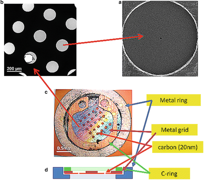

Fig. 2
Close-up views of a Zernike phase-plate device. (a) A view of a phase plate made of amorphous carbon film. The tiny dot in the center is a hole (~800 nm in diameter), through which unscattered primary electrons pass. (b) A partial view of a latticed array of phase plates. (c) A top view of a 25-phase-plate support grid (2 mm in diameter) adapted to a metal ring (3 mm in diameter). (d) A schematic of side view of a 25-phase-plate support grid and a metal ring
In light microscopy, we have the Smith/Nomarski phase contrast termed differential interference contrast (DIC). The original design of DIC, however, does not appear to be representable with a simple filter scheme involving such filters as illustrated in Fig. 1, because DIC employs birefringent optical devices called Wollaston prism before and after the objective lens. In EM we do not have a counterpart of the Wollaston prism. This methodological discordance has been recently removed with a novel scheme that uses a half-plane phase plate inserted at BFP to retard the electron wave by π (180°) (see Fig. 1e and also [5]). This setup is termed Hilbert differential contrast (HDC) [6].
If the half-plane phase plate in HDC is replaced by a Foucault knife-edge, we have schlieren optics (SO), as shown in Fig. 1f. SO is the oldest and the most popular phase-contrast scheme and has once been employed in EM as single-sideband imaging [7]. However, the loss of electrons due to the interrupt by the knife-edge has made the approach less popular within the EM community.
Comparison between the conventional (DPC) and phase-plated (ZPC, HDC, and SO) schemes suggests that almost no change is required with respect to the operation of the EM itself, as phase plates set at the BFP usually equipped apertures. However, some care must be taken in the adjustment of defocus to near focus and the alignment of unscattered primary-electron passage. Details of the operation of ZPC-EM have already been described elsewhere [8].
3 Phase Plates
Phase plates are usually made of a thin carbon film. Indeed, carbon films with thicknesses of 5–10 nm have been indispensable tools in EM experiments and can support a wide range of specimens including organic, biological, and even semiconducting materials. The films are usually made using vacuum evaporators that rely on Joule heating. The amorphous carbon films made in this manner have been especially welcome as support for biological specimens due to their relatively high electronic conductivity, which helps avoid troublesome specimen charging. Fabrication of phase plates, which utilizes amorphous carbon films, has proceeded according to the traditional methods. Nonetheless, as already mentioned, charging of phase plates has been a source of trouble in phase-contrast EM.
Stay updated, free articles. Join our Telegram channel

Full access? Get Clinical Tree


