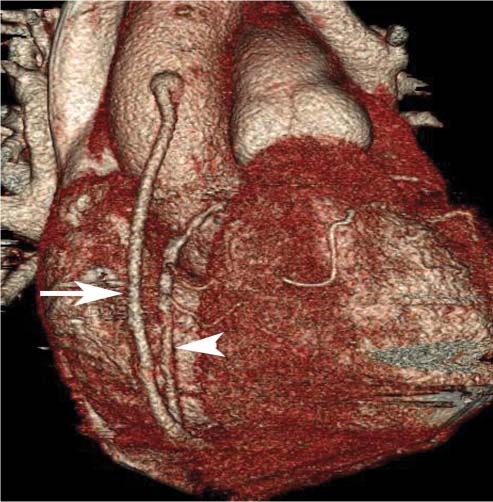
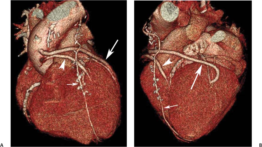
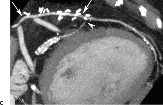
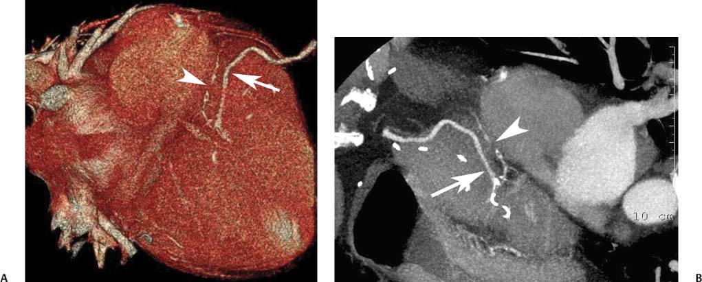
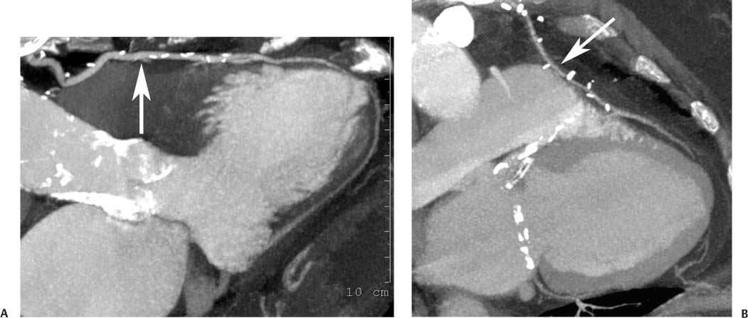
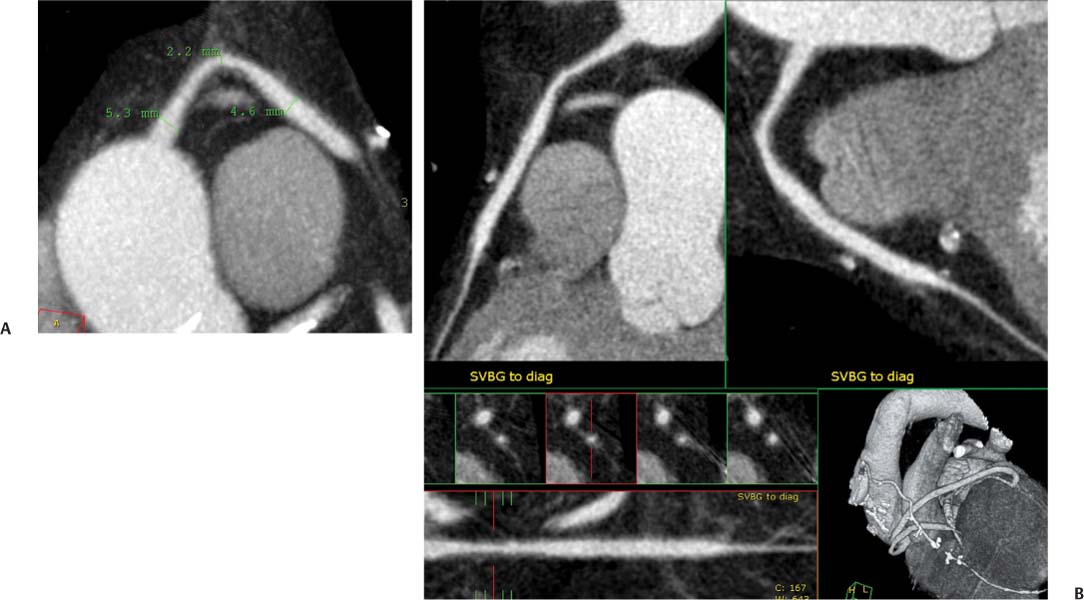
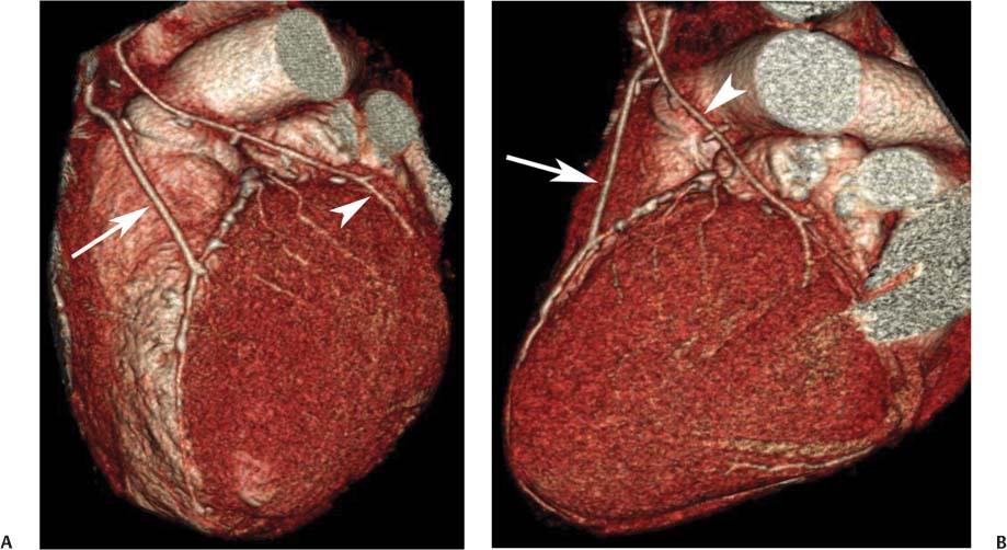
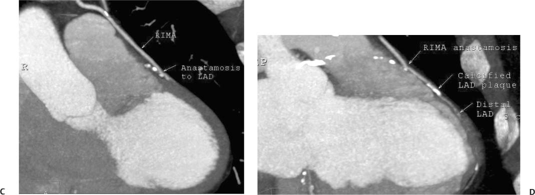
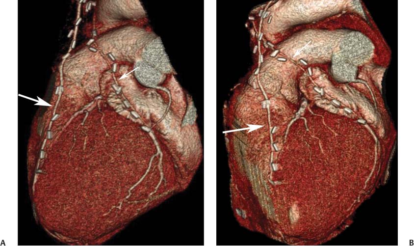
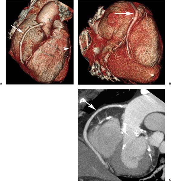
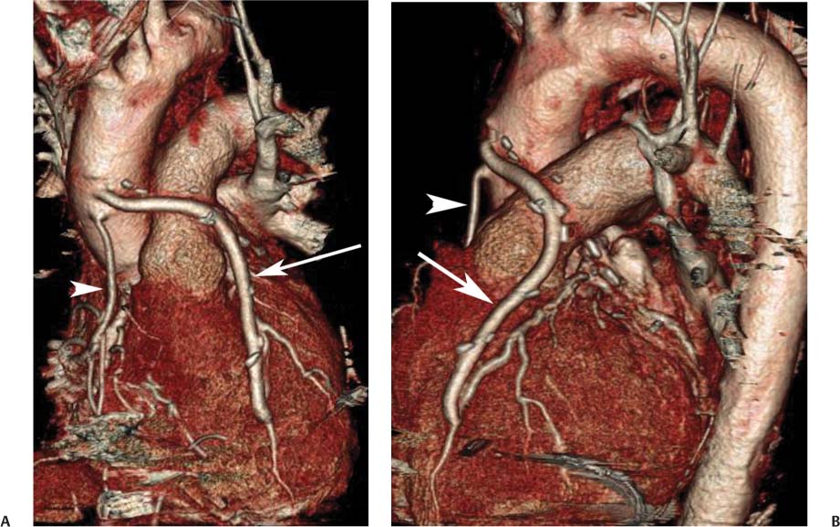
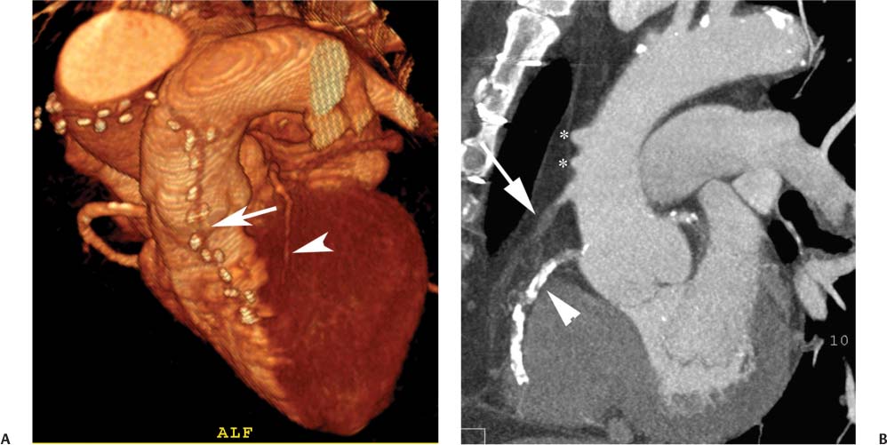
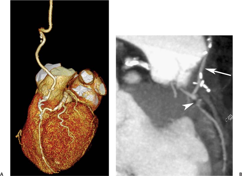
8 In addition to its application for the evaluation of native coronary vessels, cardiac CT is an increasingly valuable technique for pre-operative and post-operative evaluation of coronary bypass patients. Pre-operative evaluation of the ascending aorta, native coronary arteries, and cardiac function is critical to the planning of bypass surgery. Post-operative confirmation of bypass graft patency is important for the diagnosis and management of recurrent anginal symptoms as well as in operative planning for repeat surgical revascularization or valve surgery after coronary bypass. Traditionally, coronary artery bypass grafting (CABG) has been performed with vein grafts that extend from the ascending aorta to a target vessel on the epicardial surface of the heart (Figs. 8.1, 8.2, and 8.3). The saphenous vein (SV) is comparable in size to major coronary arteries and is easily harvested from the lower extremity without significant consequences. The SV has good early patency, but it has been noted that up to 10% of vein grafts may be closed by the time the patient is discharged from the hospital. Accelerated graft atheroma has contributed to saphenous graft failure at 5 to 10 years after coronary bypass. By 10 years about 40% of grafts have failed because of thrombosis, intimal hyperplasia, or accelerated atherosclerosis.1 As bypass surgery has evolved, arterial revascularization has become more popular. The right and left internal mam-mary arteries (RIMA and LIMA), inferior epigastric artery, right gastroepiploic artery, and radial artery (RA) have all been used (Fig. 8.4, 8.5, 8.6, and 8.7). Although vein grafts are much larger than arterial grafts (3–4 mm versus 1.5–2 mm) and vein grafting may be technically easier than arterial grafting, recent literature supports the use of all-arterial conduits when possible because of their longer patency rates compared with venous grafts.2 Coronary arteries that are suitable as target sites for bypass grafts are usually 1 to 2 mm in diameter. These include the left anterior descending (LAD) and its diagonal branches, the right coronary artery (RCA) and its posterior descending artery (PDA), and posterolateral (PL) branches and obtuse marginal (OM) branches of the circumflex artery. Early thrombosis of vein grafts following surgery can be related to technical factors, anatomic factors causing poor distal runoff, or hemodynamic factors causing sluggish flow, whereas mid- to long-term vein graft occlusion is related to proliferative intimal fibroplasia with concentric narrowing of the inner lumen (Fig. 8.8). Vein graft atherosclerosis mimics fibroplasia but is more eccentric and associated with mural thrombus (Fig. 8.9). As stated previously, atherosclerosis is typically a late process seen more than 5 to 10 years after surgery, and up to 50 to 70% of vein grafts are occluded or have a significant stenosis by 10 years after surgery. These results seem to be improving in recent years as a result of the addition of aggressive antilipid therapy in all post-bypass patients. Fig. 8.1 Vein graft to the distal right coronary artery. Surface-rendered volumetric projection demonstrates a vein graft (arrow) extending from the proximal aorta to the right coronary artery (arrowhead). The course of the graft is clearly demonstrated, but it is not possible to evaluate for stenosis on surface-rendered images. Fig. 8.2 Vein graft to the posterior descending artery (PDA). (A) Surface-rendered volumetric image demonstrates a vein graft extending from the proximal aorta around the right atrium toward the crux of the heart (arrow). A small left internal mammary artery bypass graft is also identified extending to the left anterior descending artery (LAD) (arrowhead). (B) Surface view of the crux of the heart demonstrates the vein graft as it emerges from around the right atrium (arrow) and extends toward the posterior interventricular groove. The anastomosis of the graft is not with the right coronary artery, but rather in the posterior interventricular groove with the posterior descending artery. (C) Slab maximum intensity projection demonstrates patency of this bypass graft as it courses around the right atrium (arrow). The distal anastomosis of the graft is not visualized on this image, although the graft is seen to course adjacent to the PDA at the crux of the heart. Fig. 8.3 Venous bypass grafts to the left anterior descending artery (LAD) and circumflex territories. (A) Two venous bypass grafts are identified. The more superior graft (arrow) extends to the circumflex territory. The second graft (arrowhead) extends to the proximal LAD. In addition, there is a jump graft segment (small arrow) to a diagonal branch of the LAD. (B) The anastomosis of the more superior venous bypass graft to an obtuse marginal branch of the circumflex is more clearly defined on this projection (arrow). The second anastomosis to the LAD is not as clearly visualized (arrowhead). The native coronary arteries are heavily diseased beyond the graft anastomoses and are patent for only a short distance. Fig. 8.4 Venous bypass grafts to an obtuse marginal branch and a diagonal branch of the left anterior descending artery (LAD). Left internal mammary artery (LIMA) bypass graft to the distal LAD. (A) Two large venous grafts are identified. The more superior graft extends across the free wall of the left ventricle to an obtuse marginal (OM) branch of the circumflex (arrow). The proximal portion of this obtuse marginal artery fills in a retrograde fashion, but the distal OM beyond the anastomosis is not well filled. A second venous graft crosses over the LAD (arrowhead) into a small diagonal branch. The LIMA courses anterior to the venous bypass grafts (small arrow) into the distal LAD. (B) Left anterior oblique image demonstrates the anastomosis of the upper vein graft (arrow) to the OM branch more clearly. The more inferior vein graft is identified (arrowhead). The anastomosis of the LIMA to the proximal LAD is clearly identified (small arrow). (C) Slab maximum intensity projection demonstrates the LIMA graft (arrows) anastomosis to the native LAD. The native LAD is occluded just proximal to this anastomosis (arrowhead). Fig. 8.5 Gastroepiploic artery bypass to the posterior descending artery (PDA). (A) Surface-rendered volumetric image of the crux of the heart demonstrates the distal segment of a gastroepiploic graft to the PDA (arrow). The native right coronary artery (RCA) is diseased, with a segmental occlusion just proximal to the anastomosis (arrowhead). (B) Slab maximum intensity projection image demonstrates the gastroepiploic bypass graft (arrow). The anastomosis with the PDA is obscured by overlying surgical clips. The diseased distal RCA is just to the right of the graft, with a focal occlusion in its distal segment (arrowhead). Arterial grafts exhibit a longer patency, up to and beyond 20 years. It is well established that the graft exhibiting the longest patency and survival benefit is the LIMA to the LAD graft.3 The 10-year patency of the LIMA to LAD exceeds 90%. Most failures of arterial grafts are attributable to technical errors at the graft anastomosis or a failure of the graft to mature because of insufficient runoff to the distal vessel (Fig. 8.10). Arterial grafts develop intimal hyperplasia but are highly resistant to atherosclerosis. Recent studies have advocated the use of bilateral internal mammary bypass grafts with excellent results (Figs. 8.11 and 8.12).4,5 When multiple bypass grafts are required, arterial grafts are generally preferred because of their longer patency rates. Currently the prospective single-center Radial Artery Patency and Clinical Outcome (RAPCO) Study is conducting a 10-year comparison of angiographic patency and outcome among RA, internal mammary artery (IMA), and SV grafts. Interim results of this study at 5 years demonstrated similar patency rates for all three types of grafts.6 The results of this study should help to clarify the extent to which RA grafts may be superior to RIMA and SV grafts. Fig. 8.6 Vein graft to the left anterior descending artery (LAD); radial bypass graft to the right coronary artery (RCA). (A) A vein bypass graft extends from the aorta to the midportion of the LAD (arrow). Just below the origin of the vein bypass graft, a smaller radial artery bypass graft originates from the aorta and extends to the RCA (arrowhead). (B) Left lateral view demonstrates the vein graft to the LAD (arrow). The more proximal LAD and diagonal branches are better visualized on this projection. Only the most proximal portion of the radial artery graft is identified (arrowhead). Note the discrepancy in size between the venous graft, which is much larger, and the radial artery graft. Fig. 8.7 Left internal mammary artery (LIMA) graft to the left anterior descending artery (LAD) in two different patients. Multiple surgical clips are present around the LIMA grafts. Maximum intensity projection images. (A) Patent LIMA bypass graft (arrow) to the mid-distal LAD. (B) Patent LIMA bypass graft (arrow) to the LAD. The more proximal LAD is calcified and occluded. Fig. 8.8 Venous bypass graft occlusion. (A) Occlusion of a venous bypass graft to the left anterior descending artery (LAD). Multiple surgical clips mark the course of a bypass graft extending from the aorta down to the LAD (arrow). The graft itself is not enhanced by contrast and is not visible. The native LAD is a small vessel that terminates just proximal to the anastomosis (arrowhead). (B) Occlusion of a venous bypass graft to the distal right coronary artery (RCA). The bypass graft is occluded just beyond its origin from the ascending aorta (arrow). The calcified and occluded RCA is identified just caudal to the bypass graft (arrowhead). Origins of two other patent bypass grafts are identified just superior to the origin of the occluded graft (*). Fig. 8.9 Saphenous vein bypass graft with stenosis (SVBG). (A) Slab maximum intensity projection (MIP) image through the proximal portion of the vein graft demonstrates mild narrowing of the lumen from 5 to 2 mm. (B) Orthogonal curved MIP images again demonstrate narrowing of the proximal portion of the graft. The straightened lumen view at the bottom of the figure demonstrates approximately 50% narrowing. Fig. 8.10 Left internal mammary artery (LIMA) bypass graft to the left anterior descending artery (LAD). (A) Volumetric rendering demonstrates a LIMA graft to the LAD but does not allow assessment of the vessels for stenosis. (B) Slab maximum intensity projection (MIP) of the distal LIMA (arrow) demonstrates a high-grade stenosis within the LAD just beyond the anastomosis (arrowhead). Fig. 8.11 Right internal mammary artery (RIMA) graft to the left anterior descending artery (LAD) and left internal mammary artery (LIMA) graft to an obtuse marginal (OM) branch of the circumflex artery. (A) Surface-rendered volumetric image in the left anterior oblique (LAO) projection demonstrates a RIMA graft to the LAD (arrow), as well as a LIMA graft to the circumflex distribution (arrowhead). (B) Surface-rendered image along the long axis of the left ventricle again demonstrates the two arterial bypass grafts. The calcified and diseased nature of the LAD is apparent, but the internal degree of vessel narrowing cannot be assessed on a surface-rendered image. The LIMA graft is anastomosed to a proximal OM branch as it exits the left atrioventricular (AV) groove. Grafts are typically placed into OM branches of the circumflex rather than directly into the circumflex artery within the AV groove. (C) Slab maximum intensity projection (MIP) demonstrates the RIMA down to the level of its anastomosis with the LAD. The anastomosis is widely patent, but the LAD is not visualized in this projection. (D) Slab MIP in a slightly different projection demonstrates the distal LAD beyond the anastomosis of the RIMA. The presence of calcified plaque is identified, as well as marked narrowing or occlusion of the distal LAD related to noncalcified plaque near the cardiac apex. RA bypass grafting was almost completely abandoned after early reports of high occlusion rates.7 More recently, the RA has been used with increased frequency with excellent short- and long-term patency.8 Some of the early failures may have been due to spasm of the RA, a feature more commonly seen in RAs compared with IMAs. For this reason, most surgeons place patients who undergo bypass grafting with the RA on oral nitrates or calcium channel blockers for several months postoperatively. A recent 6-year study with angiographic correlation demonstrated improved survival and greater patency of RA grafts compared with SV grafts as the second conduit in LIMA to LAD CABG.9 A similar study of 90 consecutive patients demonstrated an 88% long-term angiographic patency of RA grafts to an OM or PDA. Although this rate was lower than the patency rate for IMA grafts (96.3%), it was significantly higher than the rate for SV grafts (53.4%).10 There has been some question as to the reliability of RA grafting to the right-sided coronary system. A follow-up study to the previously mentioned RAPCO study looked at differences between RA and SV grafting to the RCA or its branches. The authors found no significant differences in patency between the SV or RA to the right-sided vessels, with a trend toward greater RA patency.11 Fig. 8.12
Bypass Grafts
 Arterial Versus Venous Coronary Bypass Grafts
![]()
Stay updated, free articles. Join our Telegram channel


Full access? Get Clinical Tree


