Pitfalls in the mediastinum
Pericardial recesses
Azygos valve
Thrombus in great vessels
Gastroesophageal junction pathologies
Cisterna chyli
Tracheo-bronchomalacia
Pitfalls in the lungs
Focal pleural thickening mimicking nodule
High-density nodule on HRCT
Artifacts-simulating nodule
Dependent atelectasis hiding nodule
Mucocele mimicking pulmonary AVM
Cystic lung disease or emphysema
Honeycombing or traction bronchiectasis or paraseptal emphysema
Dependent atelectasis or basal fibrosis
Round atelectasis
Metastatic pulmonary calcification
Congenital abnormalities presenting in adults
Pulmonary sequestration
Congenital bronchial atresia (CBA)
Congenital cystic adenomatoid malformation (CCAM)
Congenital lobar emphysema (CLE)
Paravertebral abscess or posterior basal segment pneumonia
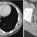
Pitfalls on CT aortogram and pulmonary angiogram
Suboptimal enhancement
Streak artifacts
Motion artifacts
Adjacent structures
12.2 Chest Radiograph Technical Errors
Image quality and artifacts are two main factors to be considered during radiographic interpretation. Quality control is required in each step for producing a good chest radiograph. A good chest radiograph should satisfy the following criteria: adequate inspiration, good positioning, optimal penetration, and correct labeling.
12.2.1 How to Evaluate Images
12.2.1.1 Adequate Inspiration
The chest radiograph should be acquired at the end of inspiration. In general, nine pairs of posterior ribs should be identified for an image considered to be obtained in adequate inspiration. A well-inspired radiograph also serves as a simple tool to estimate lung volume. The normal subject inhales about 95 % of the total lung capacity without coaxing, during an erect radiograph (Fraser et al. 1999). If a chest radiograph is obtained at any other phase of the respiratory cycle, the lung volume may be underestimated and may even mimic interstitial lung disease (Fig. 12.1). Cardiac size is estimated by calculation of the cardiothoracic ratio (CTR) on the erect posteroanterior (PA) chest radiograph. The cardiac silhouette is considered as enlarged, when the CTR is more than 50 %. However, in a supine position or inadequately inspired chest radiograph, there may be magnification of the heart size. In newborns or infants, the heart is considered enlarged when the CTR exceeds 57 % (Edwards et al. 1981).
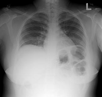
Fig. 12.1
Screening chest radiograph of large patient taken in poor inspiration and with inadequate penetration. The lung bases are not well visualized. Prominent gas-filled stomach bubble is present. There are metallic objects projected over the mediastinum and two just cranial to each lateral clavicle, produced by bra clips. All these external objects should have been removed
12.2.1.2 Positioning and Rotation
Ideally, the normal lung parenchyma must cast bilateral symmetrical homogeneous densities with gradually increased opacification toward the lung bases, due to gravity-related increased blood flow. Rotation is the most common cause of asymmetric transradiancy of the lungs. Rotation can be detected and quantified by measuring the distance between the spinous process of T4 or T5 vertebrae and the medial ends of both clavicles. Rotation may produce apparent distortion of the mediastinal border and asymmetric attenuation of the lung parenchyma (Fig. 12.2).
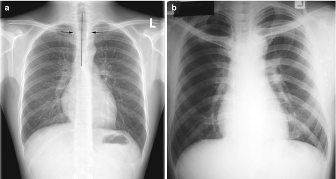
Fig. 12.2
Effect of rotated patient position. (a) Well-positioned and well-penetrated normal chest radiograph. The distances between both medial clavicular heads and spinous processes of the thoracic vertebrae are equal. Both lung fields are of homogeneous low density with the outlines of thoracic spine being just visible. (b) Chest radiograph taken in rotation. The positions of the medial clavicular heads are asymmetric and there is asymmetric density between two hemithoraces. It may be difficult to appreciate which lung is abnormal. Incidental finding of bilateral first and second rib fusions is noted
12.2.1.3 Marker and Label
The correct placement of patient identification, use of right or left marker indicating patient position, and date and time of acquisition on the acquired images are recommended. Direct marking of the side or position on the detector or film is still necessary. In a wrongly labeled image, a normal radiograph can otherwise be mistaken as situs inversus (Fig. 12.3). Mislabeling and marker placement are common human errors. In the digital era, there are many methods available to reduce this error, such as using the barcode system or DICOM modality worklist.
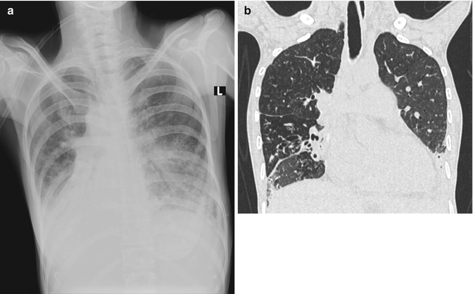
Fig. 12.3
Wrong marker placement. (a) Portable AP chest radiograph was misdiagnosed as dextrocardia with bilateral lower lung opacities. There was human error in labeling of this radiograph using electronic annotation. As the radiograph was taken in rotation, the right scapula is projected over the right upper lung. (b) Subsequent coronal reconstructed CT image (lung window) confirmed that the patient had levocardia
12.2.1.4 Penetration (Underexposure Versus Overexposure)
For conventional screen radiographs, a well-penetrated PA image shows both bone and soft tissue shadows at the mediastinum. A few thoracic vertebral bodies should normally be visible below the carina, and vascular bundles are visible through the cardiac shadow. In an underexposed radiograph, the retrocardiac region is too opaque, resulting in potential obscuration of any left lower lobe lesion (Figs. 12.2b and 12.4). In contrast, for an over-penetrated radiograph which is diffusely dark, the resultant image may mimic emphysematous lung with poorly defined bronchovascular markings and too clearly seen bony structures. Small pneumothorax, small nodules, faint opaque lesions, and soft tissue details are often not visible in these over-penetrated images.
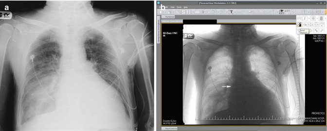
Fig. 12.4
Underpenetrated image. (a) Portable AP chest radiograph shows an opacity at the right lower lobe and faint catheter line over the left neck. There is slight underpenetration with the thoracic spine being poorly seen. (b) The digital soft copy image displayed on the workstation allows windowing to adjust density and image inversion. This enables clarification of the outline of catheter from the left internal jugular vein to superior vena cava (SVC). The end of this catheter (arrow) is located at the entry point of the SVC into the right atrium
This century has witnessed rapid development of the computer technology, including digital radiographs. Conventional screen film is being replaced by either computed or digital radiographs, which offer an instant image display, a wide dynamic range, and a linear signal response. The digital technology has solved the problem of underexposure and overexposure by allowing adjustment of soft copy images (optimizing window and level) on the computer workstation (Fig. 12.4). Digital flat-panel radiography systems based on amorphous silicon and cesium iodide not only contribute toward improving the image quality but also help in significant reduction of the radiation dose, patient waiting time, and reporting time.
12.2.2 Artifacts
Artifacts can be divided into two categories, namely, those related to patient and those related to technique. Most of these artifacts are usually easy to identify, prevent, or correct.
12.2.2.1 Patient Artifacts
Artifacts may be caused by many factors, such as poor instructions, monitoring devices, and underlying diseases. The common cause of motion artifacts is from inability to control respiration that is often encountered in unconscious patients, in improper instructions, or in children (Fig. 12.5). A few artifacts are unavoidable, for example, implanted medical devices, orthopedic instruments, or monitoring lines (Figs. 12.6, 12.7, and 12.8). Some objects such as electrocardiography (ECG) leads, necklace, hair or hairpin, underwear, and clips should be removed from the region-of-interest (Figs. 12.1, 12.4, 12.9, and 12.10). Changing clothes, removal of metallic objects out of the region-of-interest, and seeking patient cooperation before acquiring the images are essential to minimize these artifacts. Repeating the radiograph after removing suspected objects generating the artifacts may be necessary in certain situations (Fig. 12.10). Hair and hair accessories (clumps of hair, hair plait, or hair braid) can mimic a lung opacity or subcutaneous emphysema, when they overlie the thorax (Fig. 12.11).
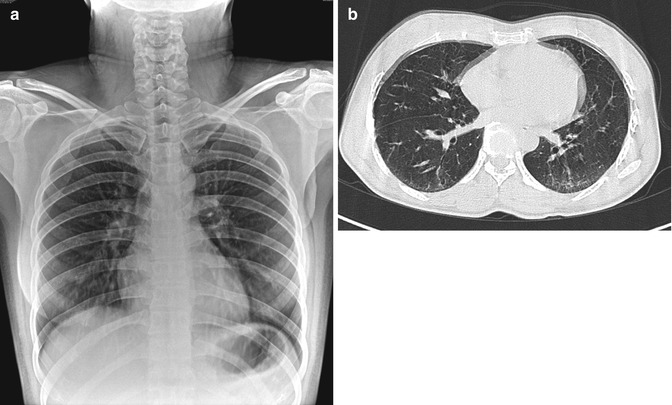
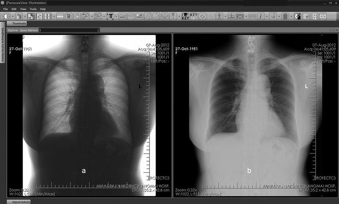
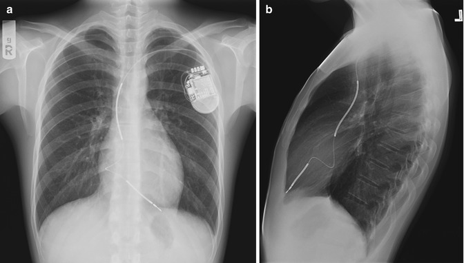
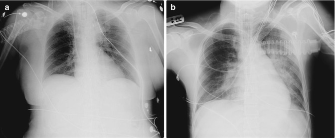
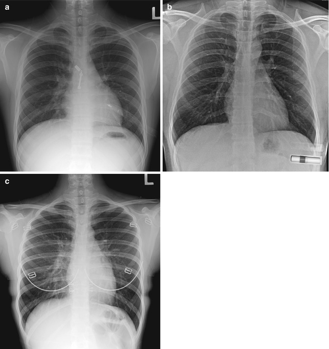
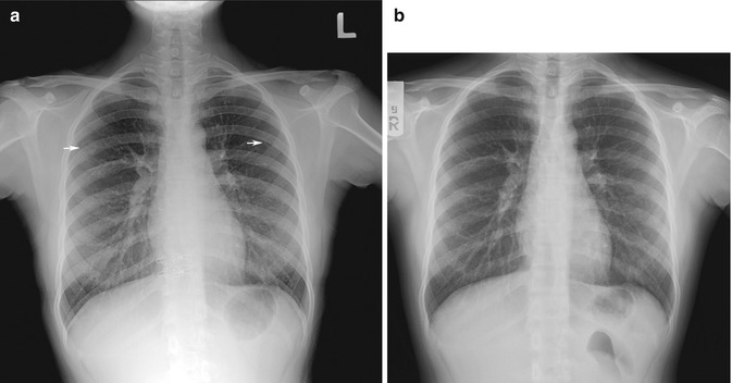
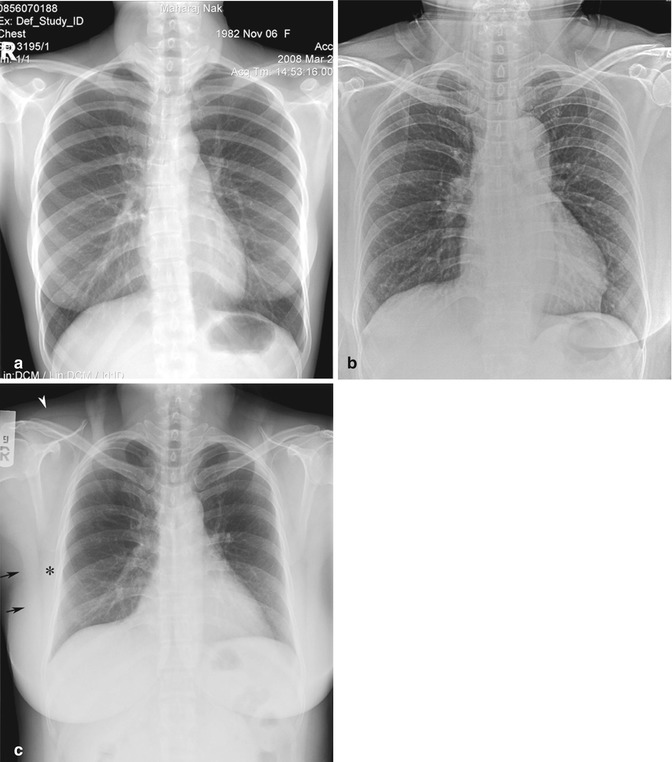
Fig. 12.5
Motion artifacts. (a) Erect chest radiograph shows unsharpness and blurring of bronchovascular structures in both lower lobes. There are multiple lucent streaks at the neck, compatible with hair artifacts that could mimic subcutaneous emphysema. (b) Chest CT image (lung window) taken at the inferior pulmonary vein level shows double bilateral cardiac contours and two anterior chest wall outlines, resulting from poor breath-holding
Fig. 12.6
Orthopedic implants. (a) Chest radiograph (inverted technique using workstation software) better shows cervical spine orthopedic implants and the lung fields, compared to the (b) conventional image
Fig. 12.7
Chest radiograph of a patient with a cardiac pacemaker. (a) Erect chest radiograph shows the pacemaker over the left upper chest which could potentially obscure a lung lesion. (b) Lateral radiograph helps show the proper position of pacemaker wire and lung fields
Fig. 12.8
Monitoring devices. (a) Portable chest radiograph shows multiple external and internal monitoring devices and wires. There is a long lucent band within the aortic shadow from the thorax to abdomen, compatible with an intra-aortic balloon pump (IABP). This device supports the circulation and is used to reduce left ventricular afterload and increase oxygenation to myocardium. It has sausage-shape balloon with retained carbon dioxide and automatic function to inflate during diastole and deflate during systole. IABP should be placed just distal to the left subclavian artery. The marker tip should be over the aortic knob. (b) Portable chest radiograph of another ICU patient shows many overlying monitoring lines that should ideally be moved away from the lung fields
Fig. 12.9
Screening chest radiographs of various external objects that should have been but were not removed. Examples include: (a) zip and pen, (b) nasal inhalant, and (c) bra
Fig. 12.10
Artifacts produced by bra components. (a) Initial chest radiograph shows two small rings over each upper thorax (arrow) and two metallic hooks projected over the spine. (b) Repeat chest radiograph after bra removal is satisfactory
Fig. 12.11
Hair artifacts. (a) Chest radiograph shows an ill-defined soft tissue mass projected over the neck, which is due to a bundle of hair within a hair net. (b) Chest radiograph shows multiple line shadows overlying the superior thorax, which may be mistaken for pneumomediastinum with subcutaneous emphysema. This is due to the patient’s long hair. (c) Chest radiograph shows two opaque columns on either side of the neck which projects over the upper chest, compatible with hair plaits. There is also suboptimum inspiration and demonstration of the trapezius muscle silhouette (arrowhead) at the right shoulder, two soft tissue bands of the right serratus anterior muscle (asterisk), and the lateral portion of the right latissimus dorsi muscle (arrow)
12.2.2.2 Technical Artifacts
Direct adverse effects on a screen radiograph or a digital storage plate before exposure could be seen as an area of abnormal density on the image. A few artifacts have a specific appearance and are easy to recognize, such as abrasions or scratches, fingerprints, static marks, light leaks, or off-center exposures on conventional radiographs (Figs. 12.12, 12.13, and 12.14). During exposure, movement of the patient, X-ray tube, or table may produce blurring of anatomic structures. Grid cutoff is seen as a white line across the image (Fig. 12.13). Cassette overlay image on film is due to the inverted position of the cassette. Double exposure or improper exposure will result in duplicated anatomic structures or a white film, respectively.
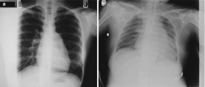
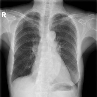
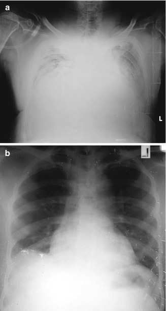
Fig. 12.12
Technical artifacts: (a) Conventional chest screen radiograph shows a white area on the right of image that resulted in loss of detail of the right lateral lung. It was caused by mis-centering of the X-ray projection. (b) In the digital image, the centering of the image was correct. The gray band over the left side of the image was out of the region-of-interest and was not cropped when the image was checked
Fig. 12.13
Grid line artifacts are seen as multiple white lines over the shoulders in this chest radiograph
Fig. 12.14
Technical artifacts. (a) Digital portable chest radiograph shows poor exposure technique and multiple white lines of scratching artifacts at the left side of the image. (b) Conventional chest radiograph shows multiple small white lines of fingerprints and abrasions over the right hemidiaphragm and left lateral part of the image. The patient also has a right subpulmonic effusion
Artifacts can occur during image processing. Overdevelopment or underdevelopment due to improper temperature and time exposure can result in the image appearing too black or too white, respectively. Yellow brown discoloration of film is caused by oxidation of residual silver halide in the film and is due to short fixing time, expired fixer, or incomplete washing of film during processing (Gray 1997). The automatic film processing machine may produce pressure artifacts from roller marks, scratch marks from improper handling, and developer spots. Mechanism of artifacts from digital image, computed radiography, and digital radiography can be divided into hardware and software causes and produce artifacts similar to those of conventional screen radiographs. Dust particle or scratches will produce a white line or dot on the image (Figs. 12.12 and 12.14).
12.3 Chest Radiograph Observer Errors Due to Display
An approved standardized light (or view) box is needed for reading radiographic films. With a lower level of luminance, certain lesions, particularly pneumothorax, interstitial lung disease, and rib fracture, may be poorly demonstrated (Herron et al. 2000). Ambient light should be maintained at a lower level than typical office lighting. Generally, a single view box size is suitable with 14 × 17 in. screen radiographs. For smaller-sized radiographs, the remaining bright borders of the view box should be covered to reduce the dynamic range over which the eye must discriminate image features (Ritenour 1996). With digital and PACS systems, soft copy images are displayed on the workstation. Detection of interstitial lung disease or rib fracture warrants adequate luminance of the workstation monitor, while detection of pneumothorax requires both luminance and high-resolution monitor (Herron et al. 2000).
The disadvantages of cathode ray tube (CRT) and liquid crystal display (LCD) monitors are that these provide less luminance than a view box. Herron et al. (2000) suggested that a true resolution of 1,024 pixels across the field of view and a monitor brightness of at least 75 foot-lamberts (260 cd/m2) are essential for primary diagnosis with PA chest radiographic images. The maximum luminance of gray-scale monitors recommended by the American College of Radiology is at least 50 foot-lamberts (171 cd/m2). Environmental light or ambient light in a digital display should be more controlled than in conventional film reading. Increased ambient light is a cause of increased image adjustment and windowing and fatigue with eye strain (Siegel and Reiner 2002). To reduce eye strain, readers are advised to take frequent short breaks, adjust and optimize background light, eliminate screen flicker and limit the number of studies for interpretation (Vertinsky and Forster 2005). Recently, image processing and analysis tools have become much better developed, and such types of equipment are more user-friendly (Figs. 12.6 and 12.15).
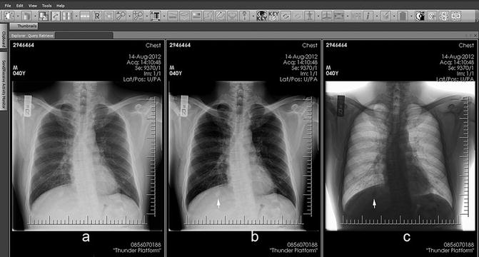
Fig. 12.15
Review areas. Chest radiographic images displayed on workstation that allows adjustment or windowing of the image in (a) conventional, (b) more contrast, and (c) inverted black and white styles. Note that the small nodule under the right diaphragm (arrow), which is a blind area of the right posterior lung, is better seen with image manipulation
12.4 Anatomic Limitations and Variations
Because the thoracic structures are arranged in one plane on frontal radiographs, the various overlying structures could obscure the lung lesions. Generally, about 40 % of lung areas or approximately 25 % of lung volume may be obscured by these structures (Mettler 2004) (Figs. 12.15, 12.16, and 12.17). Certain chest wall structures and abnormalities can be mistaken for pulmonary lesions.
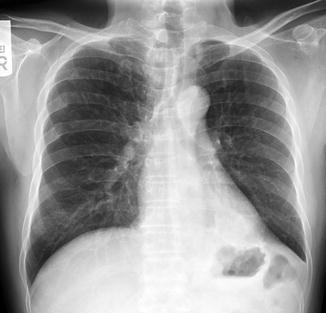
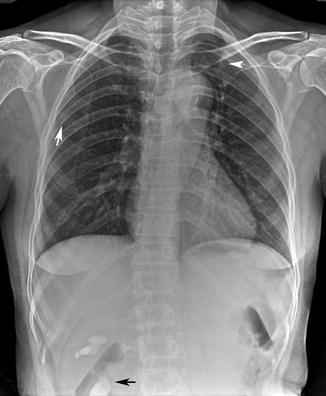
Fig. 12.16
Review areas. Chest radiograph shows multiple reticulonodular infiltrations in the right upper lobe. The focal opacity at the left retrocardiac region (review area) is difficult to see. There is loss of the normal bronchovascular bundle and increased density in this area. Multiple rib fractures involving the posterior fourth to sixth right ribs are also seen
Fig. 12.17
Review areas. Chest radiograph shows a few small nodules (arrowhead) in the left lung apex being obscured by the medial end of the left clavicle and a small well-defined nodule (white arrow) in the right upper lobe being obscured by the right scapula and ribs. Included abdomen shows a right staghorn calculus (black arrow). Readers should always look carefully at every image from the corner to corner
12.4.1 Breast and Nipple Shadows
The size and shape of breasts vary individually. They become pendulous with advancing age and pregnancy (Rosse and Gaddum-Rose 1997) (Fig. 12.18). Generally, a normal female adult breast shadow is seen as a soft tissue opacity with an incomplete border overlying the lower thorax. The inferolateral border of the breast is well-defined and sharp due to its free edge being surrounded by air, while the superior portion fades out (Fig. 12.18). The breast tissues generate an ill-defined shadow over the lower lung zones (Fig. 12.18c). As both breasts are usually not quite equal, asymmetric ill-defined opacities from breast shadows may produce confusion during image interpretation. It may sometimes be difficult to distinguish among normal breast shadows, normal lung, and either breast or lung pathology (Fig. 12.18a). Lateral views may be helpful to exclude underlying lung pathology. After breast removal for breast cancer surgery, the ipsilateral hemithorax is typically more lucent than the other hemithorax; mimicking lung emphysema or pulmonary oligemia (Fig. 12.19). Recently, new radiographic imaging tools have been added that help to separate lung tissue from the overlying bony thorax, such as dual-energy subtraction (Fig. 12.19) or digital tomosynthesis (Fig. 12.20), which enables pulmonary pathology, calcification, or bony portions to be more easily detected.
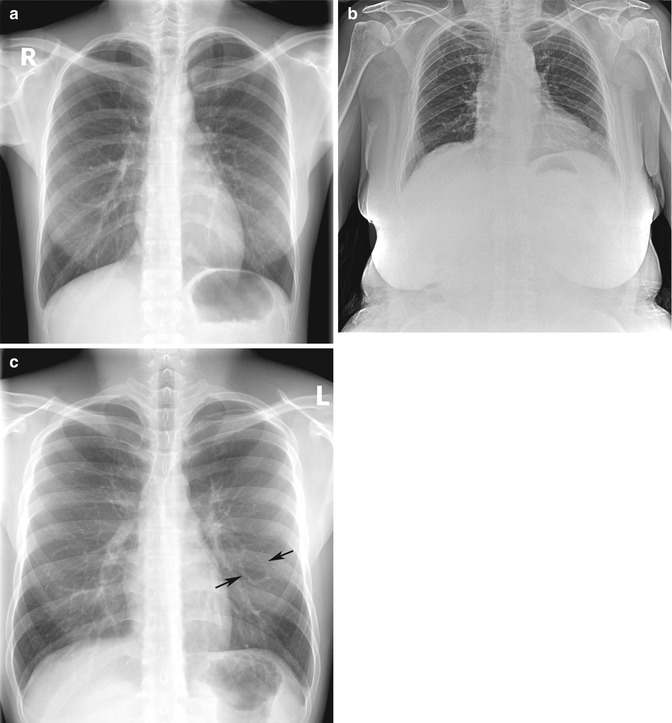
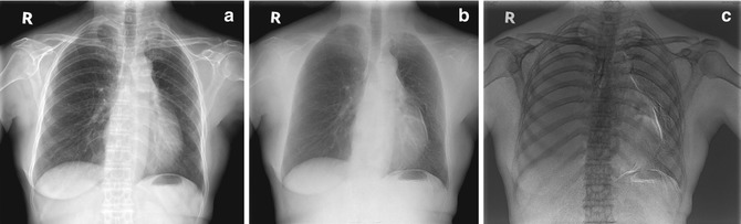
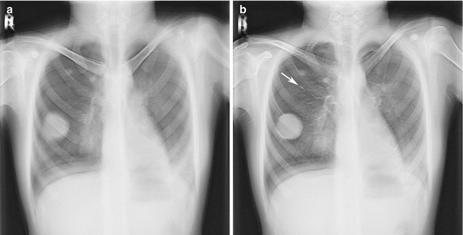
Fig. 12.18
Breast shadows. (a) Chest radiograph of an adolescent female shows an incomplete border of the breast soft tissue shadows at both lower portions of the hemithorax, causing increased density at both lower lung fields. However, the lungs are normal. (b) Chest radiograph of an elderly woman shows grossly enlarged and pendulous breasts projected over the upper abdomen. (c) Chest radiograph of a man shows that the chest wall muscle may be of various densities, depending on muscle thickness. If focal, these dense areas may be misread as ground-glass lung lesions. Note a pseudo-cavity at the left mid-lung that is formed by pulmonary vessels (arrows)
Fig. 12.19
Chest radiographs using the dual-energy technique. (a) Conventional image shows mild lucency of the left lung due to loss of the left breast from previous mastectomy for breast cancer. (b) Soft tissue image to search for lung nodules shows details of only the lung and heart. (c) Inverted bone image helps detection of bone lesion and more readily detection of calcification
Fig. 12.20
(a, b) Chest radiographs taken using digital tomosynthesis technique show the lung fields in steps or layering, similar to CT images. Using this technique, a small nodule (arrow) is seen below anterior part of right second rib, which was missed on the chest radiograph taken using the conventional technique (not shown)
Each nipple is usually noticeable on the chest radiograph as a 0.5–1 cm well-defined oval nodular density over the lower thorax (Fig. 12.21). In some cases, only one nipple is identified to be projected over the lungs. In such cases, differentiation from an intrapulmonary lesion may be difficult. For small and flat breasts, the standard solution is to repeat a chest radiograph using radio-opaque markers placed round the nipples. In the past, augmentation mammoplasty was performed by direct injection of liquid silicone and paraffin. It has now been replaced by newer procedures, due to resultant complications, such as fibrous mass, foreign body granuloma, calcification within the breast, or migration throughout the body (Erguvan-Dogan and Yang 2006; Yi et al. 2008; Yang and Muradali 2011), and serious complications, e.g., acute lung injury or pulmonary embolism, after subcutaneous silicone injection (Parikh et al. 2008). Chest radiographs show a mass or heterogeneous opacity over the lower thorax, which could be misinterpreted as a pulmonary lesion. Recent breast implants involve placing an artificial implant under the breast glandular tissue or under the pectoralis muscle. Silicone bags and its fluid component are seen as a large well-circumscribed mass at the lower chest, resulting in increased opacity projecting over the lung on chest radiographs (Fig. 12.22).
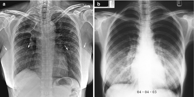
Fig. 12.21
Nipple shadows. Screening chest radiograph shows two small nodules in the right lower hemithorax and a small one in the left lower hemithorax. Both inferior ones are well defined with clear borders and are symmetrically sited on each side, compatible with nipple shadows. The right more superior nodule is calcified. A few tiny satellite nodules are seen nearby. Old granuloma is a most likely diagnosis. Both scapula project over the lung fields bilaterally
Fig. 12.22
Breast augmentation. (a) Chest radiograph of a woman with bilateral breast augmentations show well-defined silicone sacs (arrows) projected over each hemithorax and underlying chronic granulomatous disease. There are diffuse reticulonodular infiltrations and a large cavity in the right upper lobe. Normal variant of a lobulated right hemidiaphragm is noted. (b) In contrast, annual routine chest radiograph of a woman of childbearing age shows heterogeneous opacities over both lower lungs. She had a history of injected solution for breast cosmesis and no chest symptom. It is difficult to exclude lung pathology
12.4.2 Skin Tag, Mole, or Wart
A skin tag, mole, or wart can produce a nodular density similar to the nipple, resulting in a pseudonodule (Fig. 12.23).
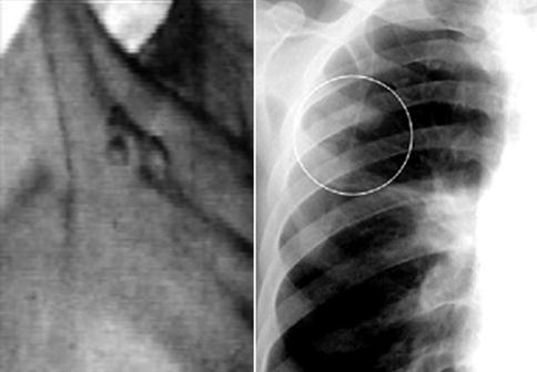
Fig. 12.23
Multiple skin warts at the right upper chest (clinical photograph; left) are seen as multiple small well-defined nodules projected over the right upper lung (circle) on the chest radiograph (right). These could be misinterpreted to be granulomatous nodules or lung metastases
12.4.3 Chest Wall Muscle
The pectoralis major and minor muscles appear as a triangular soft tissue density around each shoulder that is contiguous with the breast on the chest radiograph. The trapezius is a large triangle-shaped muscle covering the shoulder posterosuperiorly and is seen as a soft tissue density extending from its superior portion in the neck to the shoulder area on chest radiographs. The serratus anterior is a large fan-shaped muscle sheet consisting of eight thick-set digitations, which form the medial wall of the axilla. On a frontal chest radiograph of a muscular man, its shadow can be partly superimposed on the lateral margin of the lung, seen as a companion shadow with a pleural line at the first three ribs or at the middle third of thorax, or “bowling pin”-like or curtain-like shadow at the costophrenic angle (Fig. 12.11c).
12.4.4 Thoracic Cage
12.4.4.1 Rib
The upper seven true ribs and bottom five false ribs insert into the sternum as bars of hyaline costal cartilage. Calcification of costal cartilages is usually apparent after the age of 35 years. The calcification of the first costal cartilage is usually asymmetric and irregular, producing a series of circular or mottled shadows. These can be mistaken by an inexperienced reader as being a lung nodule, so-termed the “student nodule” (Fig. 12.24). Normal variants or developmental abnormalities of the ribs are common (Figs. 12.2b and 12.25) and are easily identified. Part of a small cervical rib may be mistaken as an apical lesion. Bifurcated rib or a pair of fused ribs may mimic a cavity. Congenital rib anomaly occurs with a frequency of about 1.4 % (Etter 1944), comprising cervical rib 0.2 %, forked or bifid rib 0.6 % (most often at the fourth rib), fusion or bony bridging 0.3 % (most common at the first and second ribs), hypoplastic or rudimentary rib 0.2 % (usually the first rib), pseudoarthrosis 0.1 % (first rib), and healing fractured rib 0.1 %.
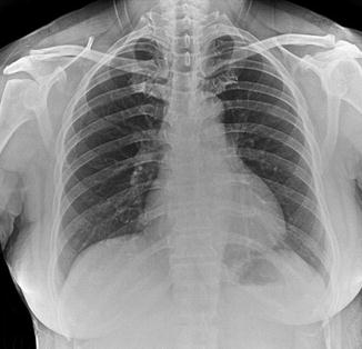
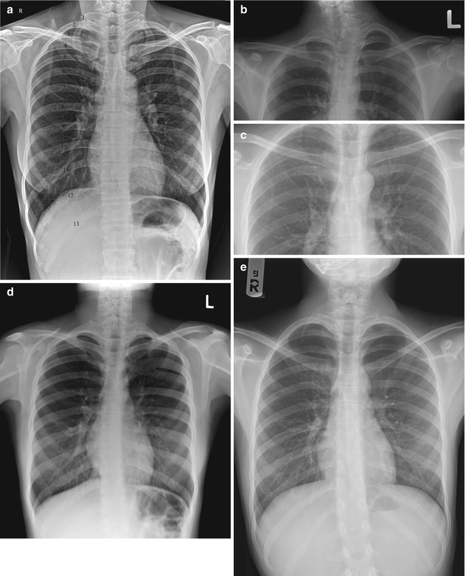
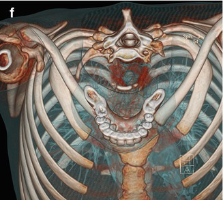
Fig. 12.24
Calcified costal cartilage. Screening chest radiograph shows a dense calcified right first costochondral junction that may be misread as a lung nodule (student nodule). The left first costochondral junction is also calcified, but to a lesser extent
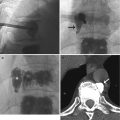
Fig. 12.25
Rib anomalies. (a) Screening chest radiograph shows supernumerary ribs. Thirteen ribs are numbered. (b) Upper chest radiograph spot image shows a small left cervical rib and hemivertebra of C7 vertebral body. (c) Upper chest radiograph spot image shows anomalous articulation of the right first rib. (d) Screening chest radiograph shows the fusion of left posterior fourth to fifth ribs. (e) Chest radiograph and (f) volume-rendering three-dimensional (VR3D) CT image shows a small right first rib and hypoplasia of the left first rib
12.4.4.2 Scapula
On a normal PA chest radiograph, the scapula should be completely projected away from the lungs, with internal rotation and abduction of the arm. However, if there is a limitation of arm or scapula movement for any reason, the scapular silhouette may overlie the upper lung fields (Figs. 12.3a and 12.21). In intensive care unit patients, almost all the chest radiographs are portable and hence obtained in a supine position, producing upper lung opacity due to the scapula and linear density from its inferior border pointing superolaterally; this may be misinterpreted as atelectasis of the upper lobe with upward shifting of the interlobar fissure.
12.4.4.3 Clavicle
The clavicle has a bony protuberance from its inferolateral part called the conoid tubercle that provides attachment to the coracoclavicular ligament (Fig. 12.26a). It is variable in size and can occur as a congenital anomaly or there may be posttraumatic ossification of the coracoclavicular ligament. The rhomboid fossa (Fig. 12.26b) is a focal irregular concavity at the inferior surface of medial end that may be mistaken as an osteolytic bone lesion (Kumar et al. 1989).
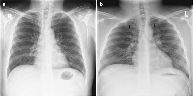
Fig. 12.26
Clavicle variations. (a) Chest radiograph shows conoid tubercles above the coracoid processes of the scapula bilaterally. (b) Chest radiograph shows bilateral focal irregular areas at the inferomedial portions of the clavicles (arrows)
12.4.4.4 Chest Wall
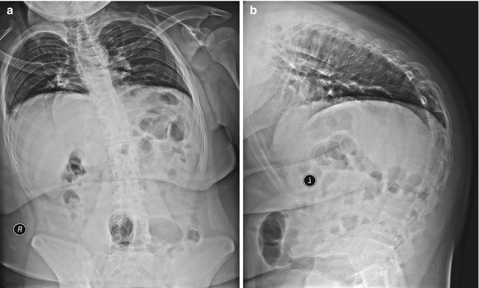
Pectus excavatum (or funnel chest) is a depression of the sternum that causes the ribs on each side to protrude more anteriorly than the sternum itself (Fig. 12.27). Its incidence is 0.13–0.4 % of the general population (Fraser et al. 1999). On the PA chest radiograph of a patient with pectus excavatum, the heart may be displaced to the left and rotated, resulting in apparent cardiomegaly. The parasternal soft tissue density in such cases can simulate a right middle lobe lesion or mediastinal mass (Fig. 12.27). Similarly, in severe kyphosis, evaluation of the lungs is limited due to crowding of bones (Fig. 12.28).
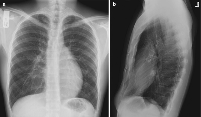
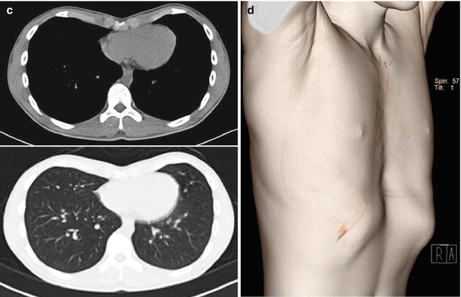
Fig. 12.27
Pectus excavatum. (a) Erect PA and (b) left lateral chest radiographs show posterior displacement of the chest wall on the heart that is mildly deviated to the left. There is apparent focal opacity at the right paracardiac area on the PA radiograph, but there is no pathological lesion detected on (c) CT images. (d) VR3D CT image also shows marked anterior depression of the sternum