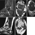
Fig. 5.1
(a) Left brachiobasilic fistulogram shows antegrade contrast injection and a stenosis in the proximal basilic vein (arrow). (b) Following angioplasty, diffuse spasm is seen in the midportion of the basilic vein (arrow). (c) Repeat fistulogram 4 days later shows satisfactory appearances of the segment of vessel where the spasm occurred. The stenosis is significantly improved following angioplasty. The arrow indicates the position of the original stenosis, given the normal vessel after angioplasty
If the spasm persists despite all measures to overcome it and if the flows are deemed satisfactory, often stopping the procedure and performing a follow-up fistulogram in 2–3 days would be helpful in assessing the response to angioplasty. If this option is chosen, it is important to ensure the patient understands the importance of returning for imaging and the clinical team caring for the patient informed in order to carry out regular clinical assessments of the fistula. In the case described, despite 300 μg of nitroglycerin and removal of the wire, the spasm persisted. The patient was rebooked for a fistulogram, which was performed on day 4 post-fistuloplasty (Fig. 5.1c), which demonstrated a satisfactory result. If the repeat fistulogram demonstrates residual stenosis, this should be retreated and nitroglycerin prepared in anticipation of possible spasm.
Vessel spasm may occur in any vessel during manipulation. This rarely requires any treatment except removal of the wire and catheter from the vessel. If the spasm is flow limiting, nitroglycerin (100 mcg) can be administered. The use of heparin during angioplasty procedures is well documented in the literature, and if severe spasm occurs in a vessel, which becomes flow limiting, in addition to the nitroglycerin, heparin 3,000–5,000 iu can be administered in order to decrease the risk of thrombosis. Again this should only be done if there are no contraindications, and it should be borne in mind that heparin effect is short-lived and will not provide anticoagulation effects beyond 1–2 h following administration. Figure 5.2 demonstrates spasm in a gastrohepatic trunk during mapping prior to selective internal radiation treatment (SIRT); this spasm occurred during manipulation of one of the small gastric feeder vessels which were embolized in order to optimize the vessel for the radiation administration.
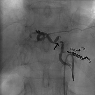
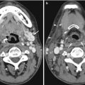
Fig. 5.2
Antegrade selective angiogram of a gastrohepatic trunk supplying the left lobe of the liver. Coils have been deployed into side branches in preparation of Y-90 administration. Spasm of the midportion of the vessel is seen (arrow) which resolved following 100 mcg of nitroglycerin
Similar effects are often seen in the uterine artery during uterine artery embolization. If the spasm is not overcome, the embolic end point may not be optimal due to the decreased flow and may result in an incomplete embolization and subsequent technical failure. In this case, again nitroglycerin can be administered in 100 μg aliquots. If the spasm does not resolve, the opposite uterine artery can be embolized and then the vessel revisited after a period of time and reassessed. If some degree of spasm persists, a microcatheter can be used and the base catheter withdrawn into the proximal anterior division of the internal iliac artery and only the microcatheter placed in the uterine artery.
Learning Points
1.
Vascular spasm can occur in any vessel and should be recognized as such.
2.
In the case of a fistula, this may be flow limiting and continued angioplasty may worsen the spasm.
3.
Always have nitroglycerin and heparin at hand for intra-arterial or intravenous administration if vessel spasm should occur.
4.
Vessel spasm often resolves if the catheter and guidewire are removed from the vessel.
5.2.2 Central Venous Catheter Malposition/Displacement
Central venous catheters are placed for a number of reasons, including venous access in patients requiring long-term antibiotics, chemotherapy, total parenteral nutrition, or hemodialysis. The insertion of venous catheters into the central venous system from the upper body includes arm, jugular, or subclavian venous access, with the latter being favored the least. When placed in a vein in the upper body, the cavo-atrial junction is the most desirable location for all catheter tips regardless of indication. When placing central venous lines, the right is preferred to the left due to the in-line anatomy and lower rate of complications, particularly when placing tunneled dialysis or infusion catheters (Nelson and Tuttle 2007). Documentation of the position of the tip is important prior to use, as infusion of cytotoxic chemotherapy or lipid-rich parenteral nutrition may cause significant complications if the catheter tip is malpositioned in a vein or is extravascular in position.
Access from the left venous system adds a further level of complexity to the procedure, as the line then takes a more tortuous course through the central veins and is possibly more likely to extend into the azygos vein or displaced into the azygos vein if the catheter is placed too high in the superior vena cava (SVC) (Haygood et al. 2012). A hemodialysis catheter placed in the azygos vein is suboptimal for adequate exchange and may cause trauma to the vessel. If, at any time after the insertion, aspiration becomes difficult or more pressure is needed to perform hemodialysis, tip position should be confirmed with a chest radiograph and a linogram.
Figure 5.3 demonstrates a tunneled dialysis catheter inserted from a left internal jugular approach. The line was used for a week, and the hemodialysis team began having difficulty aspirating from the proximal port. A linogram was performed, demonstrating the tip position at the origin of the azygos vein. No images were available at the time of insertion; however, the operative notes describe a SVC position of the catheter. The acute angle of the catheter in the neck places tension on the catheter, which may in turn cause the catheter to move upward and displace into the azygos vein. Figure 5.4a demonstrates a right-sided port inserted from an internal jugular approach. However, the port catheter was cut too short, being positioned in the upper SVC. Over time, the tip displaced into the azygos vein. The port was removed and a new port inserted (Fig. 5.4b), with the tip at the cavo-atrial junction, thus decreasing the risk of tip malposition or displacement. Figure 5.5a, b show the ideal positions for dialysis catheters and infusion lines.
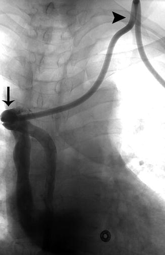
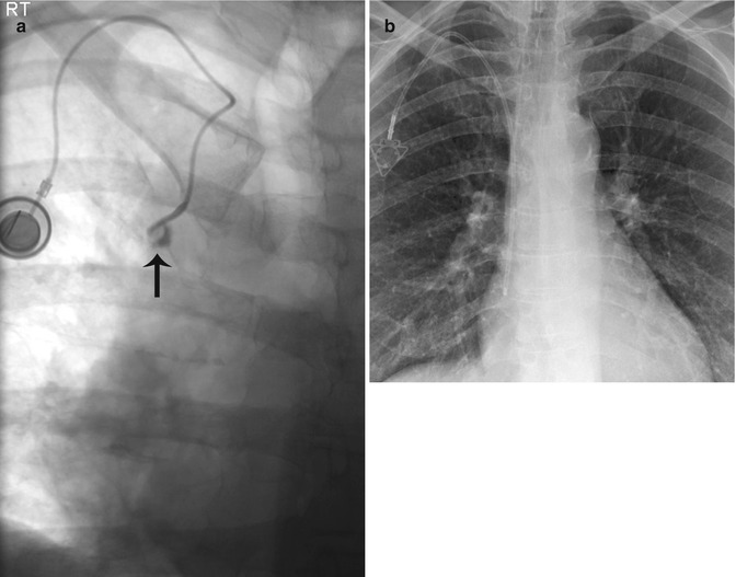
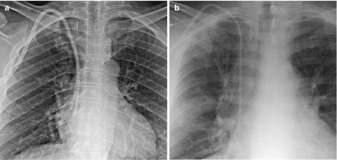
Fig. 5.3
Linogram performed through a left-sided tunneled dialysis line shows opacification of the azygos vein due to malposition of the catheter tip (arrow). The acute angle of the catheter in the soft tissue of the neck (arrowhead) creates tension on the catheter, making the catheter more prone to movement within the vessel
Fig. 5.4
(a) Linogram performed through a single-lumen port-a-cath shows opacification of the proximal azygos vein (arrow). The catheter was cut too short and positioned in the upper SVC and over time became lodged in the azygos vein. (b) The port-a-cath was replaced. Note the position of the catheter tip at the cavo-atrial junction, making the tip less likely to flip into the azygos vein
Fig. 5.5
Ideal positions for dialysis catheters and infusion lines. (a) Dual-lumen dialysis catheter with its tips positioned at the cavo-atrial junction. This position decreases the risk of thrombus formation at the tip of the catheter, and the tips in the upper right atrium allow for increased exchange flows. (b) Triple-lumen Hickman catheter with its tip at the cavo-atrial junction, which allows for administration of cytotoxic medication and decreases the risk of dislodgment of the tip and thrombus formation at the catheter tip
Learning Points
1.
Always confirm the position of the tip of any central venous catheter at insertion. The ideal position for all permanent central venous access catheters is the cavo-atrial junction.
2.
If a catheter cannot be aspirated, a chest radiograph and a linogram should be performed to confirm tip position.
3.
Left-sided access catheters are more prone to displace into the azygos vein due to the path.
5.2.3 Dextrocardia
Dextrocardia refers to a mirror-image heart situated on the right side. Dextrocardia is believed to occur in approximately 1 in 12,000 people. The orientation of the heart therefore reverses the conventional venous anatomy draining into the right atrium. This distorted anatomy has implications for complex cardiac procedures and relatively simple venous access procedures.
Failure to identify the condition may lead to difficult dialysis catheter placement or incorrect choice of the length of catheter required. Permanent dialysis catheter access placement should be avoided in dialysis patients, as fistula access is the preferred method of dialysis access. If this cannot be avoided, the following should be borne in mind when placing a permanent dialysis catheter. The preferred insertion site for a cuffed venous dialysis catheter is the right internal jugular vein (IJV). If the internal jugular vein cannot be accessed, options in order of preference include the right external jugular vein, left internal and external jugular veins, subclavian veins, femoral veins, and translumbar and transhepatic access to the inferior vena cava (IVC). Subclavian vein access should be used only when all other upper extremity or chest wall options have been exhausted (Nelson and Tuttle 2007).
Ultrasound imaging should be used in the placement of catheters in order to visualize the target vein. The position of the tip of any central catheter should be verified radiologically in order to ensure correct placement. Venous access via the right IJV would provide access to the right brachiocephalic vein, which in this group of patients crosses the midline to drain in to the SVC on the left. This may in turn lead to avoidable pitfalls including placement of an unnecessary long dialysis catheter and subsequent early catheter failure. A simple clinical history and review of the patient’s previous imaging may reveal the condition prior to embarking on the procedure. A safer approach in this group of patients would be a left IJV puncture, providing straight-line access to the SVC (Fig. 5.6a). The illustrated case is of a 56-year-old female patient with diabetes-induced renal failure and coincidental situs inversus dextrocardia. Initial catheter insertion was performed without a proper history or review of the previous images, which demonstrated the condition. The catheter was placed via a right IJV puncture with a suboptimal final result (Fig. 5.6b). The catheter was used for hemodialysis for 2 weeks and began requiring high dialysis pressures. A decision was made to revise the catheter and place a left-sided dialysis catheter. The procedure was performed and the right-sided dialysis catheter removed.
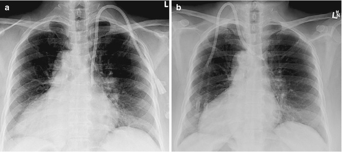
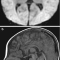
Fig. 5.6
A 56-year-old female patient with situs inversus and renal failure requiring a tunneled dialysis catheter. (a) The tunneled dialysis catheter was placed via a left IJV approach, which in this patient is the correct site for access, given the position of the SVC. This line was placed following initial incorrect placement via a right IJV approach. (b) Tunneled dialysis catheter initially inserted by an operator with insufficient clinical history. The line was placed via the right IJV, which is the correct initial access vessel. However, in a patient with dextrocardia, this is incorrect due to the position of the SVC and right atrium. The line was malpositioned in the brachiocephalic vein and failed within 2 weeks
Learning Points
1.
Always review prior imaging before embarking on a procedure. Anatomic variations may necessitate a change in access site.
2.
Ensure that during a venous access procedure from the neck, a guidewire is placed through the needle following venous puncture into the IVC in order to ensure you are in the venous system and there are no unexpected anatomic variations.
3.
Always use ultrasound imaging to access the venous system when placing venous dialysis catheters.
4.
Radiological confirmation of tip position following dialysis catheter insertion is essential in all venous access procedures.
5.2.4 Thoracic Stent Grafts
Traumatic aortic injury (TAI) is a potentially lethal injury, with out-of-hospital mortality of 86.2 %. It is second only to head injury as the most common cause of death following blunt trauma, with an incidence between 13 and 20 % (Akowuah et al. 2009). Open surgical repair of TAI is often complicated by distorted anatomy secondary to associated hematomas or pseudoaneurysms. The use of stent grafts for the treatment of abdominal aortic aneurysmal disease has encouraged many clinicians to utilize the same principles for treatment of traumatic aortic injury. Endovascular treatment of thoracic aneurysms appears initially to be an ideal alternative to open surgery. However, anatomic location, re-intervention rates, and a lack of long-term morbidity data make this treatment in many contexts unproven. This is no truer than in patients with TAI.
The landing zone for stent graft deployment is often in the distal arch of the aorta just proximal to the isthmus. Deployment of the graft in this position can in cases lead to the most proximal end of the graft sitting proud, away from the lesser curvature (Fig. 5.7a), due to the inherent energy when deploying the graft, pushing it toward the greater curvature. This phenomenon is known as bird-beaking. Bird-beaking may cause a persistent type 1 endoleak and necessitate molding balloon use, which is not favored in the aortic arch or proximal extension of the graft in order to seal the leak. This in turn may require covering of the great vessels and thus bypass surgery to ensure continued flow to these vessels.
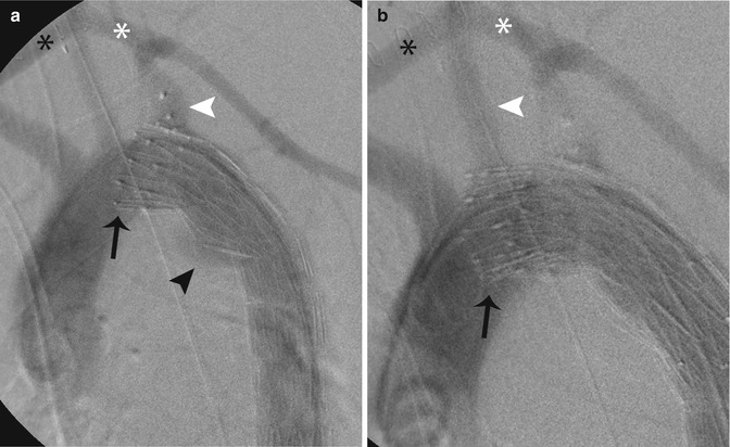
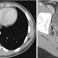
Fig. 5.7
Intraoperative aortograms following insertion of a thoracic endovascular stent graft in a 22-year-old patient with traumatic aortic injury. (a) The stent was deployed. However, due to the acute aortic arch, the proximal graft sits proud of the lesser curve (bird-beaking) (black arrow). This stent fails to exclude the aortic injury and contrast agent is seen filling the aorta at the site of injury (black arrowhead). The left subclavian artery (white arrowhead) was covered in order to gain a satisfactory landing zone; however, this still failed to exclude the injury. Note the excluder plug in the proximal subclavian artery. A left carotid-subclavian bypass (white asterisk) and a right-left carotid bypass (black asterisk) have been performed. (b) A proximal extender graft was then inserted in order to exclude the aortic injury. However, this graft too sits proud of the lesser curve (black arrow) and excludes the aortic injury. The left carotid artery (white arrowhead) origin had to be covered in order to exclude the injury. A left carotid-subclavian bypass (white asterisk) and right-left carotid bypass (black asterisk) have been performed
A 22-year-old patient was involved in a road traffic accident, sustaining blunt trauma to the chest secondary to rapid deceleration, and suffered a TAI at the aortic isthmus (Fig. 5.7a). A left subclavian-left carotid bypass was performed initially and the origin of the left subclavian artery occluded using an Amplatzer II device (AGA Medical Corporation, MN, USA). A Cook TX2 (Cook Medical, IN, USA) endovascular graft was deployed across the origin of the left subclavian artery. However, initially, angiographic images demonstrated a type I endoleak. A molding balloon was used at both the proximal and distal ends, but the leak persisted. A left-right carotid bypass was performed and an extender graft inserted across the left carotid origin (Fig. 5.7b), which sealed the endoleak. Advances have been made in the deployment of the stent grafts, with a deployment system in the Pro-Form TX2 (Cook Medical, IN, USA) specifically designed to overcome this phenomenon.
Learning Points
1.
Deployment of a thoracic stent graft in the arch of the aorta should be done in a transverse portion if possible and the areas of maximal curvature avoided.
2.
Ensure that a healthy portion of the aorta is used as a landing zone in order to maximize the chance of seal.
3.
The stent graft should be advanced past the point of proximal deployment and retract the device in order the remove and energy from the system before deployment.
5.2.5 Uterine Artery Embolization: Utero-ovarian Anastomosis
Uterine artery embolization (UAE) was first described in 1995. Since then, it has become a widely accepted alternative to hysterectomy for symptomatic fibroids. Approximately 25,000 UAE procedures are performed annually worldwide. Excellent clinical outcomes such as symptom improvement for symptomatic fibroids have been reported in numerous studies, with no significant difference between different embolic agents. However, these may take months for clinical symptomatic improvement to manifest and often patients report irregular menstrual symptoms following embolization, ranging from amenorrhea to worsening of symptoms. These trend toward improvement in more than 90 % of patients treated.
The degree of fibroid volume infarcted after UAE seen on contrast-enhanced magnetic resonance imaging (MRI) can be used to predict failure of therapy early on, if there are doubts as to the technical success at the time of treatment. Devascularization of less than 90 % of the overall fibroid volume results in significantly higher rates of clinical failure and necessity of re-intervention requiring either repeat UAE or surgery. Complete infarction may not be achieved in a certain number of patients due to difficulties in catheterization, incomplete embolization, or use of insufficient embolization material. A further factor influencing the outcome is collateral blood supply to the target organ, with the most important variants being ovarian supply. This supply can be either unilateral or bilateral, with incidences ranging from 5 to 20 % (Scheurig-Muenkler et al. 2011). Failure to identify this collateral supply at the time of intervention may result in incomplete infarction of the fibroids.
Related posts:
Stay updated, free articles. Join our Telegram channel

Full access? Get Clinical Tree


