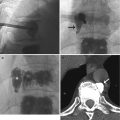
Fig. 13.1
CMR images of a 56-year-old patient with suspected cardiomyopathy. (a) Short-axis IR SSFP DCE image shows severe aliasing artifact (arrows), which limits evaluation of the ventricular septum and right ventricle. (b) When the image was repeated using a larger phase FOV, the aliasing no longer interferes with evaluation of the heart. Note the Moire fringes (asterisk) along the edges of the wrapped artifact. Moire fringes are an interference pattern most commonly seen on GRE MR images
The best way to address this artifact is to remove any signal from outside the FOV. Using a surface coil instead of a body coil so that only the area within the FOV is covered results in signal only from body parts that are within the maximum frequency range. Other solutions include the use of phase over-sampling or increasing the number of phase-encoding steps, both of which increase image acquisition time. One can also increase the FOV, which increases the signal-to-noise ratio but decreases image spatial resolution (Saremi et al. 2008).
If a very small FOV is required for improved diagnostic accuracy, one can reduce aliasing artifact by turning off some of the coils. For example, when imaging a patient with suspected arrhythmogenic right ventricular cardiomyopathy (ARVC), a small FOV centered in the free wall of the right ventricle will allow for higher spatial resolution. By bringing the small FOV anteriorly and turning the posterior coils off, wrapping artifact is nearly absent. Some modified k-space filling algorithms such as radial acquisition can also reduce aliasing. Overall, aligning the phase-encoding gradient direction with the smallest patient width, which is most commonly the anteroposterior direction, is also important, as it will maintain the body parts within the FOV.
Aliasing occurring during phase-contrast (PC) imaging is a somewhat different phenomenon. PC technique measures direction and amount flow as well as velocity within a cross-sectional area of a vessel over several cardiac cycles. On PC images, signal intensity is velocity encoded. Therefore, stationary protons appear gray, flow in one direction appears bright, and flow in the opposite direction appears dark (Srichai et al. 2009). The user defines the peak velocity encoding (VENC) value and its sensitivity and direction. Aliasing or velocity wraparound happens when the VENC is set below the actual peak systolic velocity; the velocities above the threshold will wrap around the scale appearing as retrograde flow. This artifact can be resolved by increasing the maximal velocity threshold at the scanner (Fig. 13.2). One must be careful, as setting the VENC too high will result in less accurate measurements due to increased noise and compression of flow to a narrow range.
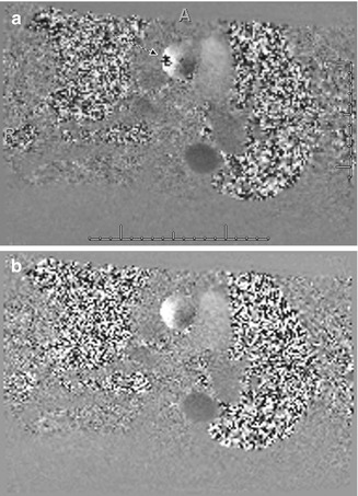
Fig. 13.2
A 60-year-old man with history of aortic valve stenosis referred for cardiac MRI. (a) Phase-contrast image taken through the proximal ascending thoracic aorta shows aliasing (arrow). (b) Repeat phase-contrast image at the same level with higher VENC shows resolution of the aliasing artifact
13.2.2 Moire Pattern
This represents an interface pattern produced by aliasing artifact, inhomogeneity of the magnetic field, or interference of echoes from different excitation modes that result in superimposition of signals of different phases that alternatively add and cancel, leading to the banding appearance (Zhuo and Gullapalli 2006) (Fig. 13.1b). This pattern is most commonly seen with gradient-echo (GRE) images and can be resolved by addressing the underlying cause (aliasing or field inhomogeneity).
13.2.3 Susceptibility Artifact
This artifact results from microscopic gradients or variations in the magnetic field strength near the interfaces of substances of different magnetic susceptibility, such as metal or air. These variations cause spin dephasing and frequency shifts in the surrounding tissues and are commonly seen surrounding ferromagnetic objects (such as metallic orthopedic hardware, dental work, or pacing wires) inside of diamagnetic materials (human body). Ferromagnetic materials (iron, nickel) have a strong influence on magnetic fields, distorting the linear magnetic field gradient, leading to dark areas (no signal) nearby the material obscuring the surrounding anatomic structures (Saremi et al. 2008).
Susceptibility artifact is accentuated by higher magnetic field strengths, GRE techniques, longer echo times (TE), and three-dimensional (3D) techniques. The best way to minimize susceptibility artifact is to use spin-echo-based sequences since GRE sequences are more sensitive to susceptibility artifacts (Fig. 13.3). When one is forced to use GRE techniques, for example, when performing cardiac cine imaging in a patient with an implanted cardiac defibrillator (ICD), using older GRE cine sequences (as opposed to the more commonly used balanced steady-state free precession sequences [SSFP]) allows for better visualization of the cardiac chambers (Fig. 13.4). Unfortunately, these GRE sequences typically have lower signal-to-noise ratio than their SSFP counterparts. Increasing the bandwidth and decreasing the echo time can also help reduce susceptibility artifact. The use of spin-echo sequences is the best way to minimize susceptibility artifact. One can also decrease the echo time and increase the acquisition matrix. Aligning the phase-encoding gradient with the same axis as the susceptibility gradient helps minimize the distortion. Proper shimming over the volume to be imaged prior to the actual acquisition is also critical to improve local field homogeneity (Zhuo and Gullapalli 2006).
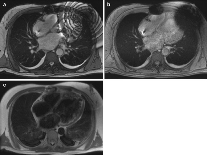
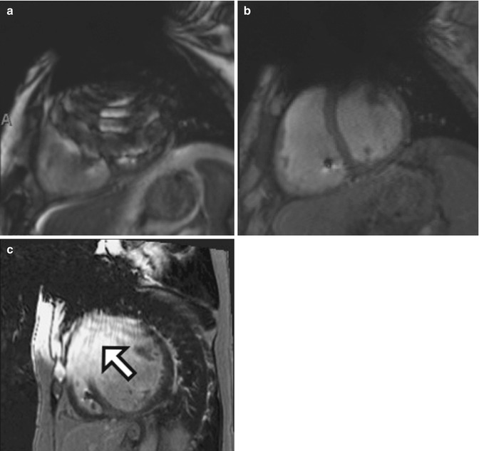
Fig. 13.3
CMR images of a 59-year-old man with severe nonischemic cardiomyopathy and a pacemaker/defibrillator. There is extensive susceptibility artifact related to the left-sided pacemaker generator. (a) Single-shot imaging utilizing SSFP, (b) GRE, and (c) black-blood turbo spin-echo (BB-TSE) images shows decreasing effects of susceptibility artifact by using different sequences
Fig. 13.4
CMR images of a 69-year-old man with severe cardiomyopathy and a pacemaker/defibrillator. There is extensive susceptibility artifact related to the left-sided pacemaker generator. Short-axis cine images at the level of the mid-ventricles using (a) SSFP and (b) GRE show how the GRE is more useful for imaging patients with pacemakers. Drawbacks include longer scan times and decreased signal to noise as compared to SSFP. (c) PSIR DCE image from a different patient with dilated cardiomyopathy shows how artifact related to the pacemaker generator can mimic DCE in the anterior and anteroseptal wall (arrow)
13.2.4 Motion Artifact
Motion artifact is a common problem encountered in cardiac imaging. It can be caused by the patient’s voluntary or involuntary movements (random) or by pulsating flow in the vessels (periodic). This type of artifact is only clinically significant in the phase-encoding direction because of the abnormal phase accumulation caused by motion along the magnetic field gradient result in ghost structures. This happens due to the development of coherence between the number of gradient steps being used and the frequency of the physiologic motion (Patton et al. 1987). Additionally, the sample of signal via frequency encoding is faster (on the order of milliseconds) than the acquisition of a single phase-encoding step (on the order of seconds), which decreases such artifact.
Voluntary or involuntary movements, such as breathing and coughing, cause random motion that leads to blurring of the image and possibly parallel bands in the phase-encoding direction (Fig. 13.5). Patients should always be clearly instructed to not move during the images acquisition. As in the case of many patients with cardiac disease, dyspnea and dry cough are common symptoms. Shortening the image acquisition as much as possible is always advised; increasing the number of concatenations, decreasing the number of slices acquired, or decreasing the phase oversampling can do this. Alternatively, the images can be acquired with the patient free breathing by increasing the averages to 3 or 4, although this will lengthen the overall scan time. There are respiratory compensation techniques, including respiratory gating, which triggers image acquisition based on the position of the diaphragm, but this technique lengthens the image acquisition time.
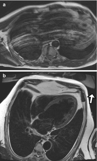
Fig. 13.5
CMR image of a 70-year-old man with coronary artery disease who had a lot of difficulty following breath-holding instructions. (a) Black-blood TSE T2-W image in the horizontal long axis shows white lines parallel the anterior chest wall. (b) CMR image in a patient who is able to hold his breath throughout the image acquisition. Some aliasing can be noted anterior to the chest wall, projecting outside the area of interest (arrow)
Another way to decrease the effects of respiratory motion on image quality is to substitute sequences utilizing single-shot k-space filling for sequences using segmented technique. Single-shot image acquisition can be performed in less than a second, allowing rapid imaging of the heart that is not as affected by patient breathing. The drawbacks are decreased special resolution and decreased signal to noise as compared to segmented techniques. Pulsation of blood vessels appears in the images as “ghost” artifacts. This artifact is more pronounced closer to the original structure and fades with distance. To solve this problem, one can use a pre-saturation pulse to saturate the inflowing protons, increase the separation between ghosts by increasing the time of repetition (TR), swap phase- and frequency-encoding directions, or use flow compensation techniques.
Cardiac motion is also a type of periodic motion and is usually resolved by ECG gating, which works well in patients with regular heart rate and rhythm. Arrhythmias, particularly atrial fibrillation with rapid ventricular response and frequent premature ventricular contractions (PVCs), cause severe degradation in image quality. This is especially true for sequences that rely on retrospective gating such as segmented bright-blood cine imaging (Fig. 13.6). Arrhythmia rejection techniques work well for occasional PVCs that happen at regular intervals because they allow deletion of these extra beats. However, these techniques are not yet robust enough to allow for quality imaging in patients with severe arrhythmias due to its unpredictability. Reverting to single shot, also known as “real-time” cine imaging, can help in cases of severe arrhythmias. The resulting cine images will have less spatial and temporal resolution as well as lower signal-to-noise ratio but are usually of diagnostic quality (Saremi et al. 2008).
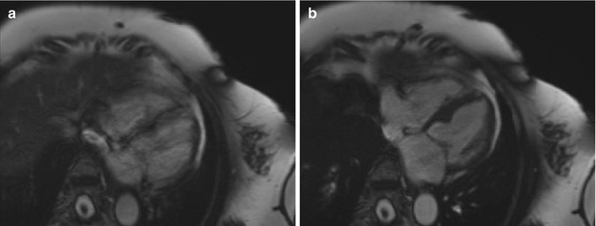
Fig. 13.6
CMR images of a 69-year-old woman with frequent premature ventricular contractions. (a) Still frame from SSFP cine imaging (retrospectively gated) shows a blurry appearance to the myocardium due to arrhythmia-related issues with ECG gating. (b) Arrhythmia rejection software was utilized, resulting in much sharper cine imaging with better definition of the myocardium
13.2.5 Delayed Enhancement Imaging
Myocardial delayed enhancement (MDE) imaging is routinely used to assess for viability and presence of infiltrative cardiomyopathies. The presence of delayed myocardial enhancement can occur in acute or chronic myocardial infarctions, infectious conditions such as myocarditis, and infiltrative cardiomyopathies such as amyloidosis and sarcoidosis (Vogel-Claussen et al. 2006). The pattern of MDE differs between these entities, allowing for more specific diagnoses. Late gadolinium enhancement images are routinely acquired 10–15 min after intravenous (IV) administration of contrast agent to allow washout of the normal myocardium. An inversion-recovery preparatory pulse is applied to null the normal myocardium, followed by ECG-gated GRE acquisition. Retained gadolinium is seen as increased signal on T1-weighted images and corresponds to the areas of fibrosis/inflammation.
The images should be acquired using the inversion time (TI) that leads to homogeneously low signal of the normal myocardium (null point) and greatest contrast between the normal and diseased myocardium, which leads to maximum signal-to-noise and contrast-to-noise ratios. The first error that can occur is imaging too early (e.g., less than 5 min after IV injection), resulting in reduced contrast difference between normal and abnormal myocardium; this can lead to overestimation of myocardial scaring. On the other hand, imaging too late (e.g., after 30 min of IV injection) will result in excessive washout of gadolinium from the scar, leading to poor signal-to-noise ratio. Another common source of error is choosing the incorrect TI, which will result in false-positive areas of myocardial-delayed enhancement. Phase-sensitive inversion-recovery (PSIR) sequences are helpful as these are less sensitive to improperly chosen inversion times (Fig. 13.7).
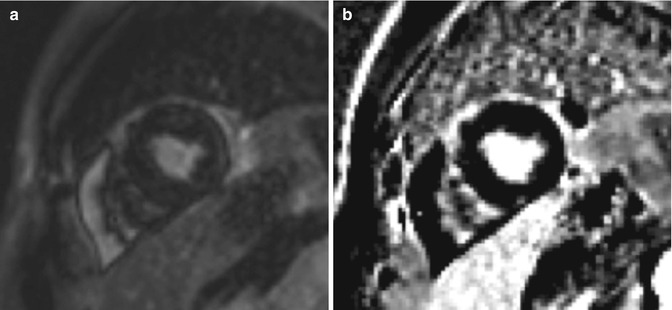
Fig. 13.7
A 49-year-old woman with a history of cardiac arrest due to Torsades de pointes was referred for CMR for evaluation of cardiac anatomy, viability, function, and investigation for myocarditis. (a) Improperly set inversion time, seen as India ink artifact on the single-shot SSFP image. (b) Same slice obtained using PSIR mitigates the artifact from an improperly set TI but can decrease sensitivity for subtle DCE
Choosing a proper inversion time is especially difficult in patients with systemic amyloidosis. The gadolinium can be rapidly cleared from the blood pool in these patients, resulting in an unusual-appearing TI scout. Also, they often have diffuse MDE, which makes it difficult to find any normal myocardium of which to set the time of inversion (Fig. 13.8). Early MDE imaging is essential for these patients, usually done 5 min after intravenous administration of contrast.
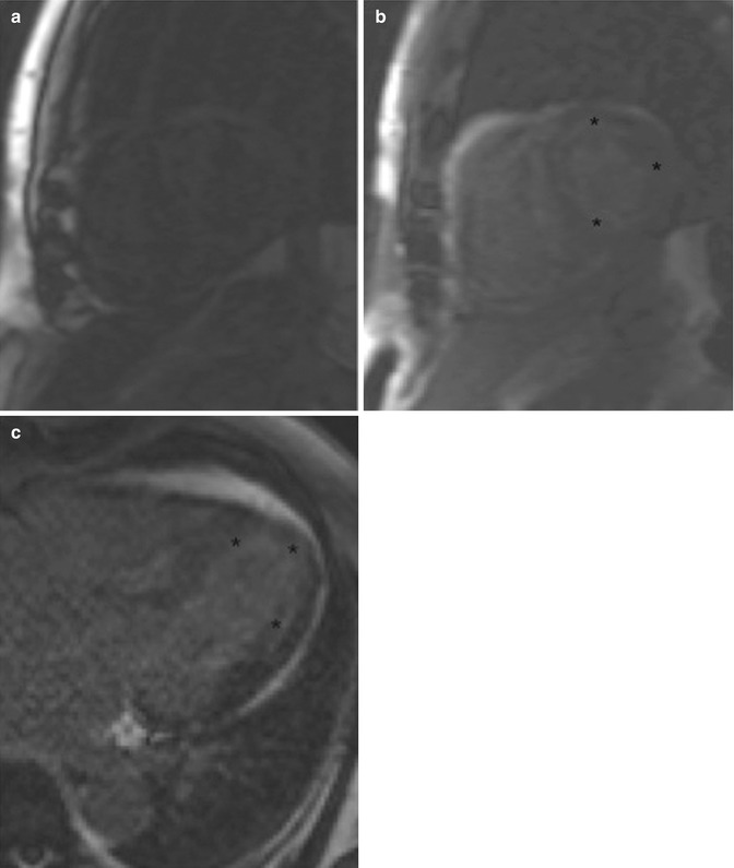
Fig. 13.8
A 71-year-old man with history of diastolic heart failure who was undergoing evaluation for myocardial viability and function. (a, b) Two images from a TI scout obtained at two different inversion times show the difficulty one can have setting the inversion time in patients with systemic amyloidosis. Note the lack of signal in the blood pool and the diffuse subendocardial delayed enhancement (asterisk) often seen in amyloidosis. (c) Horizontal long-axis IR SSFP DCE sequence shows diffuse subendocardial delayed enhancement (asterisk)
13.2.6 Failed Double-Inversion Technique Mimicking Thrombus
Black-blood techniques require a double inversion prepared half-Fourier acquisition single-shot turbo spin-echo sequence (BB-TSE). Slow or turbulent flow can lead to increased signal in the blood pool, which can mimic thrombus (Fig. 13.9). Narrowing the thickness of the slice-selective inversion pulse can reduce artifacts related to slow flow but can lead to myocardial nulling as an undesired consequence. Presence of gadolinium-based contrast agent will alter the inversion time and result in failure of the double-inversion techniques.
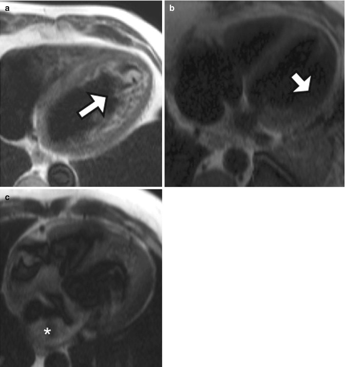
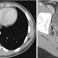
Fig. 13.9
Examples of double-inversion imaging artifacts. (a) A 56-year-old man with dilated cardiomyopathy and left ventricular ejection fraction of 14 %. High-intensity material (white arrow) is due to slow and turbulent flow in the LV apex. (b) Axial black-blood HASTE image from a different patient shows lack of the left ventricular free wall (arrow) due to myocardial nulling. (c) Axial black-blood HASTE image performed on a patient who had received intravenous gadolinium contrast agent shows many artifactual filling defects (asterisk) due to failure of adequate double inversion related to presence of contrast material
13.3 Computed Tomography
13.3.1 Intravenous Contrast Injection
Diagnostic images depend on the appropriate contrast opacification of the structures that will be analyzed. When acquiring images for coronary CT angiography (CTA), the contrast bolus should be present in the left cardiac chambers, coronary arteries, and ascending aorta. There are two ways of making sure the correct structures are opacified during image acquisition. The first technique is called “bolus timing”: a 10 ml contrast “test bolus” is injected, and images are acquired in the region of interest (ROI) over a period of time to calculate the time it takes for the injected contrast agent to reach that specific region. This calculated time is then used as the “scan delay” time between injection of the contrast bolus and the start of the actual image acquisition.
The second technique is called “bolus tracking”: an ROI is placed in a chosen region to observe the flow of injected contrast agent over time. When the desired attenuation threshold is achieved (usually between 100 and 150 HU), the scan is triggered and the images are acquired. This technique is particularly prone to errors because if the ROI is placed in the incorrect structure, the final images will be of nondiagnostic quality due to lack of adequate contrast opacification (Kroft et al. 2007). In addition, in patients with poor cardiac output, the bolus can take longer to make it to the ROI, such that the scanner may “time out” or shut down prior to peak opacification. Also, sometimes in these patients, the attenuation threshold is never reached. Therefore, in patients with known or suspected heart dysfunction leading to decrease cardiac output, the “test bolus” technique is more reliable. Another important step when performing a coronary CTA is to use a saline flush after injection of the contrast agent. This will allow for clearance of the contrast agent with high iodine concentration from the superior vena cava and right heart chambers, therefore reducing streak artifact, which can interfere with evaluation of the right coronary artery. Some institutions use a mixed or blended saline bolus that contains some contrast agent so that the right cardiac chambers are mildly opacified with contrast agent at the time of the scan.
Related posts:
Stay updated, free articles. Join our Telegram channel

Full access? Get Clinical Tree


