(1)
Imaging Center, Institut de Génétique et de Biologie Moléculaire et Cellulaire, Illkirch, France
(2)
Department of Translational Medicine, Institut de Génétique et de Biologie, Moléculaire et Cellulaire, Illkirch, France
(3)
Cell Biology and Biophysics Unit, European Molecular Biology Laboratory, Heidelberg, Germany
Abstract
Correlative light and electron microscopy (CLEM) aims at combining data acquired from the same sample through both imaging modalities. Many combinations can be found in the literature where almost any kind of light microscopy (LM) has been associated to different processing in electron microscopy (EM) and applied to a wide variety of specimen, from cultured cells to multicellular organisms. In this chapter, we focus on a technique that intends to combine LM acquisition on living cells with transmission EM (TEM) analysis. A specific attention is given to the description of a method to bring precise coordinates to the object of interest, to allow a straightforward correlation between LM and EM. Moreover, we describe how, by using high-pressure freezing as a fixation technique, dynamic events observed at the LM are captured and studied at the ultrastructural level.
Key words
Light microscopyElectron microscopyCorrelative microscopyHigh-pressure freezingAclarTargeted ultramicrotomy1 Introduction
The last two decades have been a fascinating time in the field of imaging in biology. After going through an unnecessary competition between the new and fashionable confocal microscopy and the old and complicated electron microscopy, a few scientists managed to convince their peers that one should benefit from combining both of these extremely powerful imaging modalities to take advantage of what they can offer the best. CLEM therefore became a method of choice, and one can witness today that what it offers goes beyond a simple addition of LM and EM. Indeed, by bridging high-end technologies on both sides of the resolution spectrum, CLEM is now a powerful tool for structure–function studies and will most certainly continue to serve as a valuable tool in biology to link the molecular biology with physiology.
The purpose in CLEM experiments is to combine the advantages of both imaging modalities. LM on its side offers a wide field of observation that can be adapted to a large variety of sample size, from cultured cells to full organisms. With the possibility to operate in open atmosphere, the microscopist can control the environment of his/her specimen even for long periods of time. As a consequence, the study of living samples is possible. We are now at the apogee of the use of Fluorescent Proteins (FP)-tagged proteins, which permits the fine localization of proteins in living cells or organisms. Moreover, with the breakthrough of functional imaging technologies, light microscopes can be used to monitor ion homeostasis (Ca2+, H+, K+, Cl−), voltage variations of plasma membranes, molecules diffusion in subcellular compartments, and even protein–protein interactions, conformational switch, or enzymatic activity. With the super-resolution light microscopy, a fine localization of discrete object or rare events is now possible.
Electron microscopy, on the other hand, offers high-resolution imaging of the cell ultrastructure. Affinity labeling allows a precise localization of molecules at the subcellular level; electron tomography, combined with powerful computing and image analysis, gives the possibility to achieve a close to atomic view of macromolecules in situ; serial imaging with transmission EM (TEM) or with scanning EM (SEM) and the so-called “slice and view” strategy can now render cell and tissue volumes with great precision. Moreover, the imaging conditions and processes for preparing the samples are extremely conservative and can preserve the full cellular integrity. As a consequence, the microscopist has access to a very complete and complex amount of data, in complement to the object of interest in the focus of his/her particular research. The challenge is now to compile this data in a meaningful correlation, and great efforts are employed worldwide to cover the entire resolution spectrum on individual samples.
There are different ways of defining CLEM, but it generally refers to those techniques that focus the analysis in LM and in EM on the same specimen. When the EM data acquisition can be considered as the final step in the process, CLEM can thus be defined according to the step, in the sample preparation process, at which the LM is performed (see Fig. 1).
Fig. 1
Diagram of the sample preparation workflow for TEM. A possibility to classify the different types of CLEM approaches is to relate them to the moment at which the LM acquisition is performed. As representative examples, some published work can be sited: 1. The LM is performed on living samples [11, 18, 23]. 2. The LM is performed after the chemical fixation [12]. 3. On-section CLEM where either immunofluorescence and immunogold are correlated [2, 24] or the preserved signal from fluorescent probes is correlated with EM [3, 4]. 4. The fluorescence is inspected on embedded samples [25, 26]. 5. The LM imaging is performed on vitrified samples or sections [16, 27]
The first successful attempts to correlate fluorescent signals with ultrastructure consisted in performing immunofluorescent labeling on resin sections and then immunogold fine localization on the same or on an adjacent section [1, 2]. The fluorescent signal is then used to screen large areas of the sample, to then focus on the given regions of interest. The same strategies have been used recently, with a dramatic improvement in the precision of object relocation, either by a fiducial-based targeting [3] or by the use of super-resolution microscopy [4]. Interestingly, these authors have been recording the specimen fluorescence that has been preserved during the sample preparation process and were therefore able to image the fluorescent signal directly from the sections prepared for TEM. The overlap with the ultrastructure was then accurate enough to focus on the ultrastructure of the pointed region/object of interest.
When the LM recordings are performed on living samples, one of the biggest challenges for correlation is to track the position of the object of interest throughout the sample preparation procedure for electron microscopy. Besides the sample morphology changes that are often associated to this preparation, finding back one object in its environment is very often referred as trying to find a needle in a haystack. Different strategies have been employed to perform this correlation on adherent cultured cells, and they all share the implementation of coordinates or landmarks that allow the registration of the precise location of the targeted cell or signal. The important point in these techniques is the preservation of these space cues throughout the sample preparation steps, in order to clearly see them on the polymerized block faces for precise trimming and sectioning.
Already in the late 1960s, successful attempts have been made to perform CLEM on cultured cells and to correlate live cell imaging with ultrastructural analysis [5, 6]. The strategy to locate the position of a single cell of interest was to mark the coverslip with a diamond scoring system mounted on the microscope (see ZH Price [6]). The procedure consisted in two marking steps, the first one scoring the non-cell-bearing side of the glass while the cells were still growing and being recorded by LM and the second step scoring the cell-bearing side after fixation. This last step ensured the preservation of the marks and therefore of the position of the cell of interest after the embedding step and subsequent removal of the culture substrate. A similar strategy was described recently, where a pulsed laser was used to mark and etch the surface of a glass coverslip bearing cultured cells [8].
Another way of recording precise positions is to add coordinates to the culture substrate before plating the cells. This has been first developed by acid etching of the glass surface [9]. Later, similar commercial solutions were offered with CELLocate dishes (Eppendorf—registered patent in 1993; see ref. [10]) and now with gridded Mattek or Ibidi culture dishes and coverslips. With this approach, the surface on which the cells are growing presents an embossed pattern that is transferred to the block face after polymerization of the resin. This approach was successfully and elegantly performed on frozen samples for immunogold analysis using the Tokuyasu technique [11].
Deposition of coordinates to the culture substrate by carbon evaporation also gave satisfying results in many applications. Substrates such as glass coverslips [9], Aclar [12], sapphire [13], and Formvar films [14] have been used. Finally, metal grids, such as EM grids, carrying intrinsic coordinates that have been used either for direct cell culture [15, 16] or in addition to cell-bearing sapphire discs [17].
When high-pressure freezing (HPF) is chosen as a fixation method, a few strategies have been proposed to add coordinates to cultured cells. They consist of carbon deposition on the substrate, addition of a metal grid prior to the fixation or engraving of coordinates either by hand with a fine needle or by computer-driven etching methods using either a laser or a focused ion beam [12, 13, 17, 18]. Depending on the high-pressure-freezing machine, etched sapphire discs are now commercially available and can be used efficiently in CLEM experiments.
In this chapter, we describe a strategy that was developed for CLEM on cultured cells, to be fixed by high-pressure freezing. This method has been successfully used for various cell types and applications [18–20] and allowed us to efficiently correlate fluorescent microscopy data from living cells with ultrastructural analysis.
2 Materials
2.1 Culture Substrate
2.1.1 Laser Etching
1.
Microdissection microscope: different systems can be used, from different companies. We have had satisfying results with Zeiss and Olympus machines, but present here what has been obtained with the LMD6000 (software version 6.5) commercialized by Leica Microsystems; objective lens: 10X/0.25 P (PL FLUOTARD, Leica Microsystems, Germany). Pulsed laser settings: power, 101–104; speed, 6; specimen balance, 0; offset, 60.
2.
Aclar film: thickness 2 mil (= 51 μm) Aclar® 33C from Electron Microscopy Sciences (EMS, Fort Washington, PA). Note that this product is now commercialized as Aclar® UltRx 2000, by EMS and other suppliers (e.g., Science Services GmbH).
3.
Biopsy punch, homemade system that was designed to make 1.4 mm discs: Goodfellow external diameter 1.65 mm, internal diameter 1.39 mm, wall thickness 0.13 mm, and a piece of cylindrical Teflon for the handle. To produce the biopsy punches, the tubes were cut as 50 mm long segments and then beveled with a rotating machine. The beveled angle was determined empirically to get a sharp and resistant edge.
2.1.2 Mounting on HPF Carriers
1.
HPF carriers: live cell carriers 1.5 × 0.14 Leica Microsystems.
2.
Glue: Loctite 350 (Henkel).
4.
Fine forceps.
2.2 Light Microscopy
1.
We have performed our experiments on a Leica TCS SP2-AOBS confocal microscope.
2.
Stage for the rapid loader: to fit high-magnification objective lenses, we engineered the stage based on the design from Leica Microsystems, in order to increase the diameter of the central hole (see Fig. 2) to 36 mm.
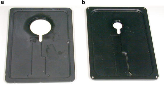
Fig. 2
Stages for the SP2 Leica confocal microscope. The in-house design (a) allows the use of high-magnification objectives, thanks to an enlarged diameter of the central hole. The commercially available stage (b) presents a smaller aperture
3.
Objective lens: water immersion 63X lens objective (63X/1.20 W Corr, apo) with a working distance of 0.22 μm, Leica Microsystems.
4.
Perfusion: Teflon tubing (Tygon, Fisher Bioblock SA); peristaltic pump (Ismatec); heating bath set to 37 °C.
2.3 High-Pressure Freezing and Freeze Substitution
1.
Leica EMPACT 2 with Rapid loader.
2.
Freeze substitution unit: Leica EM AFS.
3.
Reagents: 20 % bovine serum albumin (BSA) in culture medium, methylcyclohexane, liquid nitrogen, acetone (dried with molecular sieve dehydrate—Sigma Fluka), uranyl acetate (Lauryl Lab, France—10 % stock solution in methanol), osmium tetroxide crystals (EMS), glutaraldehyde (25 % aqueous stock solution, EMS).
4.
Embedding molds: reagent bath and flow through rings from Leica Microsystems.
2.4 Targeted Ultramicrotomy and TEM
1.
Ultramicrotome (Ultracut S, Leica Microsystems).
2.
Cryotrim 20 diamond knife (Diatome).
3.
Histo diamond knife (Diatome).
4.
Maxtaform copper–rhodium slot grids (EMS).
6.
Eyelashes.
7.
Forceps.
3 Methods
3.1 Preparing the Culture Substrate
3.1.1 Etching of the Pattern
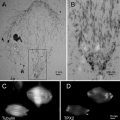
Aclar sheets, 2 mil (51 μm thick), are cut as rectangles (76 mm× 26 mm) and placed on a glass slide on the stage of the laser microdissection microscope (LMD6000) for etching of a series of patterns that are designed as an array of squares (70 μm wide), with a central landmark in the shape of an “L” which gives asymmetry to the system (see Fig. 3a, b). This central mark is crucial to define the relative position of each square and therefore to constitute a reliable system of coordinates. The actual design of the pattern can be adapted to the purpose of the study and can consists of squares, crosses, or points, as long as the landmarks are found on the block face after embedding.
Fig. 3
 Microwave-Assisted Processing and Embedding for Transmission Electron Microscopy
 Electron Microscopy of Microtubule Cytoskeleton Assembly In Vitro
 Biological Applications of Energy-Filtered TEM
 Freeze Fracture and Freeze Etching
 Correlative Light and Electron Microscopy Using Immunolabeled Sections
 X-Ray Microanalysis in the Scanning Electron Microscope


Examples of patterns that can be used to etch the Aclar film (a and b). A central, asymmetric mark gives an orientation to the coordinate system. To mount the Aclar round piece (c), drops of glue are deposited on the inner rim of the live cell carrier. A blunt eyelash is used to control this deposition and to minimize the amount of glue. The Aclar film is then dropped on the carrier, using fine forceps. The round pieces are cut from the etched Aclar film (d), which is clearly visible on the mounted carriers. Adapted from Spiegelhalter et al. [18]
Related posts:
Microwave-Assisted Processing and Embedding for Transmission Electron Microscopy
Electron Microscopy of Microtubule Cytoskeleton Assembly In Vitro
Biological Applications of Energy-Filtered TEM
Freeze Fracture and Freeze Etching
Correlative Light and Electron Microscopy Using Immunolabeled Sections
Stay updated, free articles. Join our Telegram channel
Full access? Get Clinical Tree
