and Martin Sachse2
(1)
National Institute of Health, Eunice Kennedy Shriver National Institute of Child Health and Human Development, Bethesda, MD, USA
(2)
Institut Pasteur, Imagopole, Paris, France
Abstract
More than 30 years ago two groups independently reported the vitrification of pure water, which was until then regarded as impossible without a cryoprotectant [1, 2]. This opened the opportunity to cryo-electron microscopy (cryo-EM) to observe biological samples at nanometer scale, close to their native state. However, poor electron penetration through biological samples sets the limit for sample thickness to less than the average size of the mammalian cell. In order to image bulky specimens at the cell or tissue level in transmission electron microscopy (TEM), a sample has to be either thinned by focused ion beam or mechanically sectioned. The latter technique, Cryo-Electron Microscopy of Vitreous Section (CEMOVIS), employs cryo-ultramicrotomy to produce sections with thicknesses of 40–100 μm of vitreous biological material suitable for cryo-EM. CEMOVIS consists of trimming and sectioning a sample with a diamond knife, placing and attaching the section onto an electron microscopy grid, transferring the grid to the cryo-electron microscope and imaging. All steps must be carried on below devitrification temperature to obtain successful results. In this chapter we provide a step-by-step guide to produce and image vitreous sections of a biological sample.
Key words
Cryo-ultramicrotomyCryo-transferCryo-transmission electron microscopyTrimmingSectioningVitrification1 Introduction
Conventional electron microscopy of cells and tissue, which consists of chemical fixation, dehydration at room temperature, and resin embedding, suffers from several artifacts such as material aggregation and extraction. In cryo-EM these artifacts are avoided, and the sample can be imaged close to a native state. However, resolution in cryo-TEM as in conventional TEM is limited by the imaging setup of the microscope itself and by sample thickness. Cryo-electron tomography (cryo-ET) can be applied to study plunge-frozen whole cells but it is restricted to a thin (<500 nm) periphery of the cell whereas the central area remains inaccessible. Cryo-ultramicrotomy technique—CEMOVIS, developed by Jacques Dubochet and coworkers, enables a scrutiny of the cells and tissue by cryo-EM [3–5]. In this technique a life specimen (i.e., cell suspension or tissue with a thickness up to 200 μm) is vitrified by high pressure freezing, directly sectioned in the cryo-ultramicrotome and subsequently imaged in a cryo-electron microscope. Since CEMOVIS does not necessarily involve sample purification, fixation, and no dehydration is required; it is an ultimate and reference technique for structural cell biology. However, CEMOVIS comes at a price. It is not an absolutely artifact-free technique: sections are impaired with mechanical artifacts as compression, knife marks and crevasses [6]. In fact, precise sectioning of vitreous biological samples is technically difficult, and it would not be possible without long-standing efforts in microtome and diamond knife development.
CEMOVIS can be combined with cryo-electron tomography (cryo-ET) in a technique refereed as Tomography of Vitreous Sections (TOVIS) [7–9]. This opens up the possibility to retrieve three-dimensional and high-resolution information from vitreous sections. However, section undulations and incomplete attachment to the grid support result in large eucentric height differences on a small area; hence, the tilt-series collection and alignment is challenging. A recently developed technique to attach sections to the grid by electrostatic charge rather than by mechanical force improves section attachment to the grid and makes TOVIS more feasible [10]. In spite of sectioning artifacts the macromolecules within the vitreous section have preserved molecular structure as tested by electron diffraction [11, 12]. Cryo-ET, together with subtomogram averaging, provides structural details of intracellular material with a molecular resolution. Subtomograms can be extracted from tomograms of vitreous sections and a structure obtained from X-ray crystallography can be fitted into the electron density of an average subtomogram [13].
Although CEMOVIS is a priori incompatible with immuno-labeling, vitreous sections can be imaged in the cryo-fluorescent microscope utilizing endogenously expressing fluorescent fusion protein. The fluorescent image can then be correlated with cryo-electron micrograph in order to obtain the location of fluorescently tagged protein within the cell [14].
The current technical limitation of CEMOVIS is sectioning artifacts. The size of the crevasses increases with the increasing thickness of the section and a search for a region of interest in the electron microscope with a thickness higher than 100 nm is difficult due to the high electron density of crevasses [6]. Thus, a future technical challenge is to further minimize sectioning artifacts by using specialized diamond knives, for example, an oscillating knife manufactured by Diatome [15] to produce thick sections (300 nm), which can be used for cryo-ET. Another challenge is to localize proteins in vitreous sections with high precision using correlative light electron microscopy strategically applied for Lowicryl sections [16].
CEMOVIS can be applied to answer both cell and structural biology questions, and with cryo-electron tomography and correlative light electron microscopy, it opens an avenue to a structural cell biology in which the macromolecule structure can be studied in the native environment of a cell.
2 Materials
2.1 Equipment
1.
Cryo-microtome either UC6/7 equipped with FC6/7 cryo-chamber (Leica Microsystems, Vienna, Austria) (see Fig. 1c, d, e) or PT-X/XL equipped with CR-X cryo-chamber (RMC, Tucson, AR) (see Fig. 1a, b).
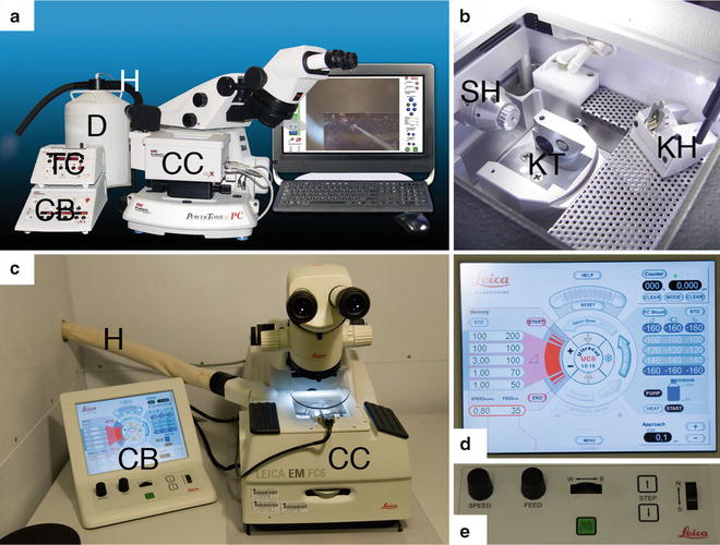
Fig. 1
Overview of the two commercially available cryo-microtome systems. (a) RMC PC microtome equipped with a crX cryo chamber (CC). The lower control board (CB) regulates the microtome settings whereas the upper control board (TC) sets the temperature in the cryo chamber. A hose (H) connects the dewar (D) with the pump to the cryo chamber. (b) View into the cryo chamber with the sample holder (SH) and knife holder (KH) to be inserted into the knife table (KT). (c) A Leica UC6 microtome equipped with a FC6 cryo-chamber (CC), which is connected via a hose (H) to the pump and the dewar with liquid nitrogen (not shown). Left of the microtome is the control unit (CB), which consists of a touch screen and a part for mechanical settings. (d) Touch screen of the UC6. On the right side of the screen the settings for the speed and nominal feed of sectioning can be selected with four stored settings. On the left side is the temperature control with four stored settings. In the centre the three different light sources are regulated as well as settings of the cutting window. The lower part allows for regulating the strength of the ionizer/crion system. The upper part shows the progress of the arm of the microtome and its reset function. (e) Lower part of the control unit for the mechanical settings. The speed for sectioning is adjusted with the most left button. The second left button allows setting the nominal feed for sectioning. With the central wheel the knife table is moved in an east-west direction. The wheel on the right moves the knife table in a north–south direction for the approach to the sample. A stepwise approach can be done with the two buttons next to the wheel. The central green button starts and stops the automatic sectioning
2.
Static line ionizer (Diatome AG, Biel, Switzerland) or Leica EM crion (AC/DC version) (Simco, Lochem, The Netherlands) (see Fig. 8a-d).
3.
Cryo-diamond knife for sectioning (35° angle) and cryo-diamond knife for trimming with 45° trimming angle (Diatome AG) ( see Fig. 4c).
4.
Single Tilt Liquid Nitrogen Cryo-Transfer Holder, Model 626 (Gatan, Pleasanton, CA) (see Fig. 9a).
5.
Gatan 655 Dry Pumping Station (Gatan).
7.
TEM CM120 (Philips, Eindhoven, The Netherlands).
2.2 Tools
1.
Eye lash glued with nail polish on wooden stick (see Fig. 2a).
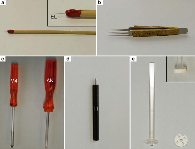
Fig. 2
Tools for manipulation inside the cryo-chamber. (a) Eyelash (EL) mounted on a wooden stick with nail polish. The insert shows a higher magnification. (b) Fine forceps (Dumont No 5) for the handling of the grids in the cryo-chamber. Cork plates were glued with epoxy resin to the side of the forceps to isolate the forceps and to avoid burning of the fingers during longer manipulations. (c) On the left the key with the M4 thread (M4) to lift out knives or the knife holder from the cryo-chamber. On the right is the Allen key (AK). (d) The tightening tool (TT) to fix the sample in the sample holder, knife in the knife holder and to adjust the clearance angel on the knife holder. (e) Homemade cryo-grid box. The long handle of the lid is convenient for manipulation in the cryo-chamber of the microtome
2.
Containers for transfer (e.g., lid of 50 ml falcon tube).
6.
TEM grids (1000 mesh copper grids with carbon film, or C-flat grids, or quantifoil 7U/7U grids with an additional layer of carbon film).
7.
Cryo-glue (mixture of ethanol and 2-propanol in a 1:3 ratio).
8.
Dextran (35–45 kDa) in PBS or in another solution.
2.3 Samples
Unicellular organism can be frozen either in copper tubes (outer diameter 650 μm, inner diameter 300 μm) using the Leica EM-pact/EM-Pact2 (Leica microsystems) or in gold tubes (see Fig. 3b, c) (outer diameter 300 μm, inner diameter 200 μm; Goodfellow Corporation, Oakdale, CA) with the Baltec HPM010 (Abra-fluid, Widnau, Switzerland). The addition of cryoprotectant in the surrounding medium for the sample is mandatory here to vitrify the surrounding medium as well. For this we use 20 % high molecular weight dextran (35–45 kDa) in PBS or in another solution, if required. Tissue can be frozen in the aluminum/brass planchette holders (see Fig. 3a) with a depth of 200 μm using the HPM010.
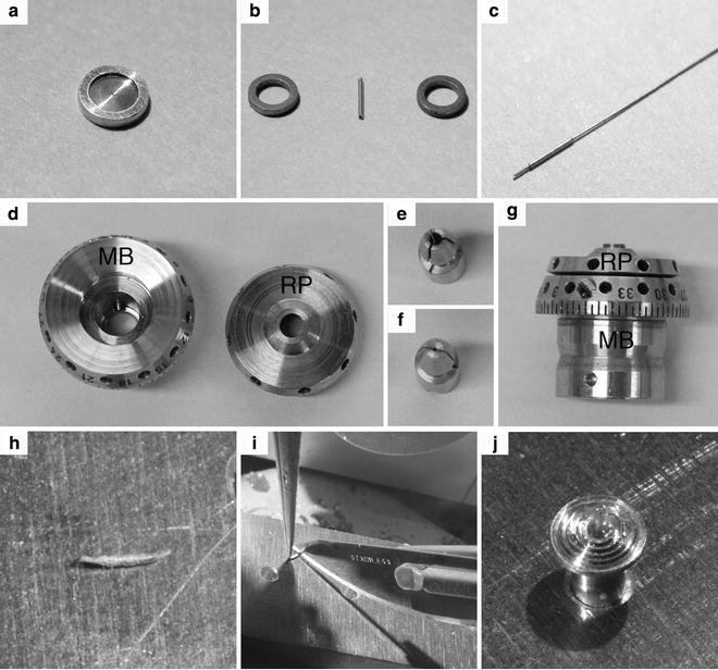
Fig. 3
Sample holders for the HPM 010. (a) An aluminum planchette with a 200 μm-deep cavity to freeze tissue samples. (b) Gold tube for freezing of samples in suspension. After loading, the tube is clamped between the two steel rings and loaded into the sample holder of the HPM 010. (c) Gold tube with a steel piston inserted for loading of the sample. (d) The main body (MB) and the flat round plate (RP) of the sample holder. (e) The sample clamp for the pins of the sample holder. (f) The sample clamp for the copper tubes of the EM pact system. (g) Side view of the assembled sample holder, which shows the 360° scale on the MB. (h) Gold tube after freezing with the two ends clamped by the steel rings. (i) With a precooled scalpel the clamped ends are cut away in the cryo-chamber. (j) Cut tube mounted on a pin with cryo-glue
3 Methods
3.1 Cryo-Sectioning
3.1.1 Preparation of the Cryo-Chamber
1.
Fill the dewar of the microtome with liquid nitrogen (LN2) and insert the pump slowly. Connect the pump with the hose and start cooling down the cryo-chamber to −140 °C.
2.
3.
Before placing the knife holder (see Fig. 4a) in the cryo-chamber set the clearance angle to a value of 6° (see Fig. 4b), insert the trimming knife to the left position of the knife holder and fix it using the tightening tools (see Fig. 4c, d).
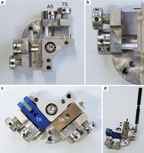
Fig. 4
Knife holder and knives. (a) Top view of the knife holder with the two lanes for knives with 90° angle in respect to each other. On the outside of each lane is one screw (TS) to tighten the knife and a second (AS) with a grade to adjust the clearance angle of the knife. The central screw (CS) of the knife holder is to fix the knife holder to the knife table in the cryo-chamber with the Allen key. (b) Detail of the TS and CS. The connection (CN) allows inserting and removing the knife holder with the M4 key. (c) Knife holder with trimming knife (TK) and sectioning knife (SK) mounted. (d) The tightening tool allows fixing the knives and adjusting the clearance angle within the cryo-chamber
4.
Lock the position of the knife table by a lever on the side of the cryo-chamber to avoid any undesirable movement, which can damage knives during mounting in the knife holder.
5.
To transport the knife holder with the knives into the cryo-chamber use a key with a M4 thread, which can be screwed into the knife holder. To make more room for mounting the specimen, lock the knife table with knives in the backmost position inside the cryo-chamber. Allow the knives to cool down (5–10 min). The chamber must be cooled down to at least −140 °C before inserting the samples to prevent their devitrification.
3.1.2 Mounting the Specimen
The sample holder of the Leica UC6/FC6 consists of three parts: (1) the main body (see Fig. 3d) that is inserted into the arm of the microtome, (2) the sample clamp inserted into the center of the main body (see Fig. 3e, f), and (3) the flat round plate screwed on the main body (see Fig. 3g). Turning the flat round plate clockwise against the main body will tighten the central sample clamp and fix the sample. There are two types of the sample clamp differing in the hole diameter. The sample clamp with a wide hole diameter (see Fig. 3e) is used for samples frozen in gold tubes or for tissue samples. The sample clamp with a narrow diameter (see Fig. 3f) is used for samples frozen in copper tubes using Leica EM-pact.
Once the temperature in the cryo-chamber is stabilized, take out the samples from the LN2 and transfer them into the cryo-chamber using a transfer container. For all of the following steps it is important that all forceps and other materials that come into contact with the sample, or are used to manipulate the sample, should be precooled to avoid devitrification of the sample.
Copper tubes. Insert the copper tube into the sample clamp placed inside the sample holder. Tighten the inserted copper tube using the tools for the sample holder of the cryo-microtome (see Note 1).
Gold tubes. Samples frozen in the gold tubes need to be mounted on pins. First cut away the clamped ends of the gold tube using a precooled scalpel (see Fig. 3i). Place the pins in either a homemade metal block with appropriate holes or in the outer holes of the knife holder of the Leica UC6/FC6. Next place a drop of cryo-glue onto the precooled pin and mount the gold tubes such that a small part is sticking out of the glue (see Fig. 3h). To harden the cryo-glue, cool down the chamber to −160 °C, subsequently placing the pin with the mounted gold tube into the sample holder and tighten as described above.
Planchettes. Carefully remove the frozen tissue from the planchette using a precooled scalpel and tweezers and then mount the tissue with cryo-glue on a pin (see Note 2).
3.1.3 Trimming
Proper trimming of the block is crucial to obtain good cryo-sections. The aim is to trim a squared, flat-topped pyramid (see Fig. 5d). If the sample is in either a copper or gold tube, both metals are soft enough that they can be trimmed away without damaging the diamond trimming knife. This is different for materials such as aluminum or brass, which contain impurities and can damage the trimming knife. In this case we advise the use of two trimming knives: one dedicated for the removal of the metal and the second for the trimming of the block.
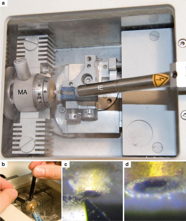
Fig. 5
Trimming of the sample. (a) Top view of the cryo-chamber ready for trimming. The sample is fixed in the sample holder and the trimming knife is close to the gold tube to trim the surface. The ionizer (IE) is mounted with its tip pointing towards the knife edge. (b) One tightening tool holds the central part of the sample holder. With the second tightening tool the disk of the sample holder is turned clockwise until the sample is locked. (c) The left side of the block is trimmed with the right side of the trimming knife. (d) Trimmed sample
1.
 Microwave-Assisted Processing and Embedding for Transmission Electron Microscopy
 Electron Microscopy of Microtubule Cytoskeleton Assembly In Vitro
 Biological Applications of Energy-Filtered TEM
 Freeze Fracture and Freeze Etching
 Correlative Light and Electron Microscopy Using Immunolabeled Sections
 X-Ray Microanalysis in the Scanning Electron Microscope


Set the position of the sample holder to 0°. The 360° scale on the sample holder allows for precise 90° rotation.
Related posts:
Microwave-Assisted Processing and Embedding for Transmission Electron Microscopy
Electron Microscopy of Microtubule Cytoskeleton Assembly In Vitro
Biological Applications of Energy-Filtered TEM
Freeze Fracture and Freeze Etching
Correlative Light and Electron Microscopy Using Immunolabeled Sections
Stay updated, free articles. Join our Telegram channel
Full access? Get Clinical Tree
