and William P. Sharp1
(1)
School of Life Sciences, Arizona State University, Tempe, AZ, USA
Abstract
Freeze fracture depends on the property of frozen tissues or cells, when cracked open, to split along the hydrophobic interior of membranes, thus revealing broad panoramas of membrane interior. These large panoramas reveal the three-dimensional contours of membranes making the methods well suited to studying changes in membrane architecture. Freshly split membrane faces are visualized by platinum or tungsten shadowing and carbon backing to form a replica that is then cleaned of tissue and imaged by TEM. Etching, i.e., removal of ice from the frozen fractured specimen by sublimation prior to shadowing, can also reveal the true surfaces of the membrane as well as the extracellular matrix and cytoskeletal networks that contact the membranes. Since the resolution of detail in the metal replicas formed is 1–2 nm, these methods can also be used to visualize macromolecules or macromolecular assemblies either in situ or displayed on a mica surface. These methods are available for either specimens that have been chemically fixed or specimens that have been rapidly frozen without chemical intervention.
Key words
Electron microscopyPlatinum replicasRapid-freezingDeep-etchingRotary shadowing1 Introduction
1.1 History
Although metal shadowing had been used in the 1940s to visualize biological materials in the transmission electron microscope [1–5], it was not until 1957 that Russell Steere published the first accounts of his development of a device that could fracture a frozen specimen and then metal shadow the fractured surface [6, 7]. Following Steere’s innovation, Stanley Bullivant developed a similar device [8, 9] and Hans Moor, working with Balzers AG in Lichtenstein, was able to design a unit that went into commercial production [10–13]. The Balzers BAF 400D instrument, a descendent of these early models, is illustrated in Fig. 1a and includes an under table pumping system with control panels and an above table vacuum chamber and control units for the specimen pedestal and electron beam guns. Manufacture of the Balzers unit was taken over by Baltec and then by Leica in 2008, the unit becoming the Leica EM BAF 060 (see Fig. 1b). Since 1990, a number of freeze fracture units have become available [14] and both the Leica EM BAF 060 and the JEOL JFD II (see Fig. 1c) units are in common use today.
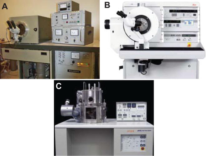
Fig. 1
Freeze fracture units. (a) The Balzers BAF 400. This model was available either with an oil diffusion pump (400D) or a turbomolecular pump (400T). (b) The Leica BAF 060 which is equipped with a turbomolecular pump. (c) The JEOL JFD II. This unit formerly used a turbomolecular pump but is now available from RMC/Boeckeler fitted with a cryopump. (b) is a courtesy of Leica Microsystems; (c) is reproduced by copyright permission from JEOL
The Balzers unit went through a number of design generations over a period of 40 years resulting in a robust instrument consisting of the following components (see Fig. 2): (1) A vacuum chamber in which both specimen fracturing and metal shadowing takes place, (2) A specimen pedestal plumbed with liquid nitrogen flow through so as to maintain the specimen temperature between −130 °C and −80 °C, (3) A liquid nitrogen cooled knife, knife holder and microtome capable of fracturing the specimen at a series of depths, (4) Electron beam guns for atomization and deposition of platinum-carbon and carbon coatings on the fractured specimen, (5) A high voltage power supply to control electron beam gun deposition, and (6) A pumping system for the chamber consisting of an oil diffusion pump or turbomolecular pump in series with and backed by a mechanical pump. Further features that improved its use included a specimen pedestal for rotary shadowing, a quartz crystal monitor for real time measurement of metal and carbon deposition on the specimen, and a liquid nitrogen-cooled shroud to scavenge water vapor in the vicinity of the specimen.
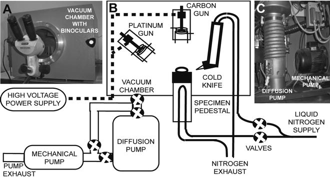
Fig. 2
Design of a typical freeze fracture unit—the Balzers BAF 400D. (a) Front door to the vacuum chamber with binocular microscope and specimen viewing window. (b) Diagram showing the major components and utilities within the vacuum chamber. (c) The pumping system below the chamber consisting of a mechanical pump and diffusion pump in series. (b) is modified from Chandler and Robertson [67]
All freeze fracture units today incorporate additional improvements over this basic design. Many machines include separate air locks for accessing the electron beam guns during refurbishing. In addition, vacuum locks for reloading specimens and changing knives are also used to further increase specimen throughput.
Initially, the freeze fracture process was thought to split ice away from membrane surfaces but with the work of Branton [15–17], it was demonstrated that the cleavage plane traveled through the hydrophobic interior of bilayer membranes with the result that two surfaces were revealed: the hydrophobic surface of the outer monolayer, referred to as the “E” or “extracellular” face, and the hydrophobic surface of the inner, or cytoplasmic monolayer, referred to as the “P” or “protoplasmic” face [18]. This terminology is straight forward when applied to the plasma membrane, but when applied to organellar membranes is consistent in that “P” face always refers to the hydrophobic surface of the monolayer in contact with the cytoplasm while “E” face always refers to the hydrophobic surface of the monolayer facing away from the cytoplasm.
Visualization of the fracture faces by metal shadowing was achieved by platinum-carbon atomization, initially by resistance guns and later by electron beam guns which accelerated and directed the metal atoms to the fractured surface at a specific angle, typically 45°. The platinum recrystallized on the frozen surface to form a thin layer of metal “islands” whose density and thickness varied with the topology of the facture face. In this manner, the three-dimensional nature of the replica can be appreciated even when viewed face on during microscopy. Figure 3a depicting a sea urchin egg cortex, demonstrates this effect when platinum is applied from a single direction so as to produce shadows (white in the microscope but black here in negative images) and a range of platinum densities that reveal a single layer of cortical secretory granules just under the plasma membrane. Comparison with a thin section of the same region (see Fig. 3b) reveals that the fractured surface follows the plasma and granule membranes thus revealing membrane architecture difficult to visualize in sections. Closer inspection of the plasma membrane faces demonstrates that the “P” face and “E” face are decorated with differing densities of intramembrane particles (IMPs) and that the stumps of cross-fractured microvilli are seen in the “P” face (see Fig. 3c) while corresponding microvillar indentations are seen in the “E” face (see Fig. 3d). Intramembrane particles were postulated to represent transmembrane proteins that upon fracturing are retained in one monolayer and extracted from the complimentary monolayer, leaving a hole that is quickly obliterated by deposition of water vapor [19]. Confirming evidence for this hypothesis came when Branton demonstrated that the reconstitution of erythrocyte band 3 protein in liposomes resulted in the appearance of IMPs in the liposome fracture faces [20].
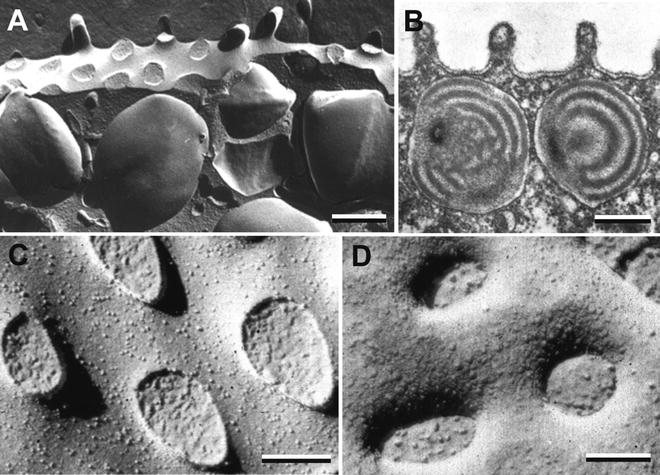
Fig. 3
The sea urchin egg cortex seen in thin section and freeze fracture replicas. (a) Platinum replica of the egg cortex showing cortical secretory granules lying just under the plasma membrane. (b) Thin section of the egg cortex revealing short microvilli on the egg surface and the onion-like internal matrix of the secretory granules. (c) The “P” face of the plasma membrane displaying stump-like remnants of fractured microvilli extending from the egg surface. (d) The “E” face of the plasma membrane incorporates invaginations leading to the interior of microvilli. Note that all images of platinum replicas in this chapter (excepting Fig. 8) are negative images. As seen directly on the electron microscope, shadows lack platinum and appear white. One can electronically reverse these to produce negative images in which platinum deposits appear white and shadows black. In this respect, negative images are similar to scanning electron micrographs and provide improved three-dimensional recognition by our visual system. Scale bars a, b = 0.5 μm; c, d = 0.1 μm. All panels are reproduced from Chandler and Heuser [24], with the permission of the Rockefeller University Press
Freeze fracture methodology has grown to include a large array of techniques. The diversity of techniques is mainly due to a large number of approaches in how the specimen is frozen, to the variety of shadowing procedures used, and to the different degrees of ice sublimation (“etching”) that can be employed. In addition, techniques ancillary to electron microscopy such as cytochemistry, immunocytochemistry, and tomography have been successfully employed in combination with freeze fracture and replica production. Table 1 outlines this variety of techniques that make freeze fracture a versatile tool in the electron microscopist’s arsenal. An overview of the evolution of freeze fracture and freeze etching techniques has been prepared recently by Heuser [21].
Table 1
Methodologies commonly employed with freeze fracturing and etching
Technique | Features | Uses | Comments | References |
|---|---|---|---|---|
Standard freeze fracture protocol | Glutaraldehyde fixation, glycerol cryoprotection, freezing in nitrogen slush or liquid hydrocarbon, platinum and carbon replication | Routine preparation of tissues and cell suspensions to visualize membrane P and E faces. Visualization of membrane architecture, membrane proteins and junctions | Fastest but extensive etching is prevented by glycerol. Artifacts due to chemical fixation and glycerination require interpretation | |
Rapid freezing and freeze fracture | Ultra rapid freezing of specimen by plunging, spraying, cold metal block contact, or high pressure freezing. Chemical fixation and cryoprotection are not used | Capturing of rapid membrane architectural changes in superficial tissue layers or cell suspensions | Avoids chemical fixation and cryoprotection artifacts. Allows substantial etching if desired. Freezing must be ultrarapid to avoid ice crystal growth | |
Quick freezing, deep etching and rotary shadowing (QF-DE-RS) of tissues | Specimen is fixed with glutaraldehyde and passed into 15 % methanol to remove salts. Specimen is ultrarapidly frozen. After fracturing, extensive etching of ice exposes a 0.5–1 μm thick layer of biological structure | Reveals true surfaces of membranes. Excellent method to visualize the cytoskeleton or extracellular matrix | Salt deposition will occur during etching if specimen has not been passed into distilled water or 15 % methanol | |
Rapid freezing and freeze drying of cells and cell fragments | Cell fragments are fixed with glutaraldehyde, rinsed with distilled water, rapidly frozen, then etched until all ice is removed | Membrane trafficking events, e.g., endocytosis. Extracellular fibrous networks | Salt deposition will occur during etching if specimen has not been passed into distilled water. Similar results can be obtained by critical point drying of cell fragments followed by rotary shadowing | |
Quick-freezing and freeze drying of macromolecules and macromolecular assemblies | Purified proteins/assemblies adhered to mica sheets and rapidly frozen. Fracturing and freeze drying is followed by rotary shadowing at low angles | Visualization of macromolecular geometry, protein aggregation, nucleic acid conformational changes, protein assemblies, protein/nucleic acid binding | Protein adhesion to mica depends on appropriate mica preparation. In some cases, similar results can be obtained by spraying of macromolecules onto mica and air drying prior to shadowing | |
Freeze fracture cytochemistry | Cells or cell fragments treated by cytochemical procedures prior to freezing fracturing and replicating by the standard protocol | Localization of membrane sterols (e.g., cholesterol). Localization of enzymes producing heavy metal labeled products | Localization is indicated by membrane perturbations or adhering heavy metal products | |
Freeze fracture immunocytochemistry | Cells or tissues are processed by colloidal gold immunocytochemistry either before or after fracturing. Replicas formed include colloidal gold markers | Localization of specific membrane proteins | Several variations of the procedure are in use including “label-fracture”, “fracture-label” and “SDS fracture-label” | |
Freeze fracture stereology and tomography | During EM imaging, freeze-fracture replicas which are inherently three dimensional are rotated to access this information | Presentation of stereo images and construction of three-dimensional structural models | A goniometer stage is required |
1.2 Freeze Fracture Techniques
1.2.1 Standard Procedures with Glutaraldehyde-Fixed Tissues
Developed over a period of years, the standard procedure is to chemically fix small tissue pieces with aldehydes, glycerinate for cryoprotection, freeze in a metal specimen carrier, and mount on a brass table that is inserted into the freeze fracture unit. An excellent overview of standard tissue preparation techniques for freeze fracture is available [22]. Because freezing of tissue leads to growth of ice crystals that distort cellular structure at the electron microscopic level, tissues must be cryoprotected by infiltration with high concentrations of glycerol (25–35 % v/v), with the result that many more ice crystals are nucleated but their growth is slow thereby resulting in an extremely fine granularity that does not disrupt structure. It was quickly learned that glycerination without prior chemical fixation of the tissue results in artifactual membrane blebbing and IMP redistribution [23]. Therefore, tissue is typically fixed with glutaraldehyde before glycerination and freezing. Use of osmium tetroxide as a fixative, while common in material embedded in epoxy resin and sectioned, is not compatible with the freeze fracture process because it prevents membrane splitting and formation of panoramic membrane faces. Small tissue cubes or pellets of isolated cells, fixed and glycerinated, are placed on gold–nickel alloy carriers shaped like top hats, and then frozen in a liquid cryogen. Liquid nitrogen is unsuitable as a cryogen because its ability to absorb heat is small and its boiling point is too low. As a result, it boils and forms an insulating layer of gas around the specimen resulting in very slow freezing and growth of relatively large ice crystals even in glycerinated specimens. For many years dichlorodifluoro-methane (Freon 12) was the cryogen of choice until its discovery as an ozone layer depleting agent and removal from the market. Although, Freon replacements such as R-22 and R134a are in use, R-22 is also ozone depleting and due to be phased out by 2020 and R134a is thought to contribute to greenhouse warming; both have gone largely untested in their possible use as a cryogen for freeze fracture work. Thus, the two most common cryogens currently in use are small hydrocarbons such as liquid propane or a nitrogen slush. Traditional freezing of specimens by plunging into liquid nitrogen-cooled cryogen is done by handheld tweezers. Alternatively, machines are now available such as the Leica EM GP, the Leica EM CPC, the EMS-002 or the Gatan Cryoplunge 3 that provide for automated plunging of grids and freeze fracture specimens into liquid propane. Alternatively, nitrogen slush can be generated by repeated evacuation of liquid nitrogen with a either a common mechanical pump or a dedicated instrument such as the Vit-Master in which boiling of the liquid extracts heat to produce a semisolid slush.
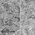
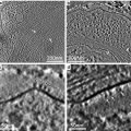
Fracturing of the frozen specimen is typically carried out in a vacuum of 2 × 10⁻⁶ mbar with the specimen temperature being held at −130 °C. Immediate shadowing of the freshly cleaved specimen from an angle of 45° with platinum (“unidirectional shadowing”) followed by carbon to strengthen the replica, results in clean membrane faces framed by smooth ice surfaces that have not been etched as seen in Fig. 4a. In this figure, note that some membrane surfaces can be difficult to distinguish from the surrounding cytoplasmic ice. In contrast, if the specimen is held at −110 °C and allowed to “etch” for 15–30 s between fracturing and shadowing, a modest amount of ice is sublimated leaving a rough patina on the non-membrane surfaces. This allows one to easily distinguish smooth membrane surfaces from roughened ice surfaces. As shown in Fig. 4b, in which a sea urchin egg cortical granule (cg) is undergoing fusion with the plasma membrane (pm), this rough patina identifies the aqueous pores formed during exocytosis. In Fig. 4c, these roughened aqueous pores can be distinguished from pores covered by a membrane diaphragm (arrows) which represent an interesting intermediate structure in the pore forming process [24]. The usefulness of etching standard specimens is limited, however, because deep etching of specimens prepared by the standard protocol is not possible due to the low vapor pressure of the glycerol cryoprotectant.
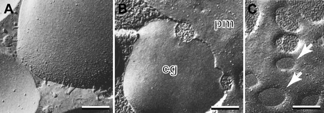
Fig. 4
Mild etching allows ice and membrane faces to be distinguished. (a) Granule membranes in a rapidly frozen mast cell are not easily distinguished from unetched cytoplasmic ice. (b) Aqueous pores joining plasma (pm) and granule (cg) membranes in a chemically fixed sea urchin egg are easily identified by their rough patina created by brief etching. (c) In the same specimen, etched aqueous pores are easily distinguished from pores covered by a membrane diaphragm (arrows). Bars = 0.1 μm. (b) and (c) are reproduced from Chandler and Heuser [24], with the permission of the Rockefeller University Press
1.2.2 Specimens Rapidly Frozen Without Chemical Fixation or Cryoprotection
In order to avoid ice crystal damage of electron microscopic specimens that have not been cryoprotected, freezing rates of at least −50,000 °C per second must be used [25]. These rates can be achieved by several different means. Very thin specimens such as cells cultured on dialysis membrane can be frozen by manually plunging into liquid propane (see Fig. 5a) or by using an automated machine as described in the previous section. Alternatively, cell suspensions or tissues no greater than 50 μm thick can be housed between copper planchets that are sprayed with liquid propane in a propane jet freezer such as the RMC MF-7200 (Fig. 5b) designed by Staehelin and Gilkey [26] or the Balzers JFD30. In contrast, relatively thick specimens can be frozen by being pressed against a liquid-helium or liquid nitrogen-cooled copper block, a process known as “slam freezing” or “cold metal block freezing.” This process can be carried out by any one of several machines built for this purpose: the “CryoPress” designed by John Heuser [27], the Life-Cell metal block freezer (now out of production) and the Leica EM MM80 E that is still produced (see Fig. 5c). Finally, one can utilize high pressure freezing in which specimens up to 1 mm3 are enclosed in a planchet that is subjected to 2,100 bar pressure while being frozen with liquid nitrogen [28, 29]. This process can be carried out by a number of commercial units such as the Balzers/Baltec HPM 010, now the Leica EM HPM100 as described in the companion chapter on high pressure freezing.
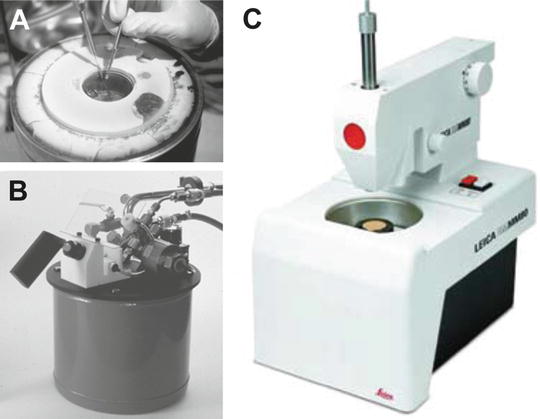
Fig. 5
Three types of instruments used for rapid freezing. (a) Liquid nitrogen-cooled bath of propane for manual plunge freezing. (b) RMC/Boeckeler Propane Jet Freezer that aims liquid propane under pressure at both sides of a metal specimen carrier. (c) Leica EM MM80 E Cold Metal Block Freezer in which a tissue face is rapidly pressed against a gold-plated copper block cooled by liquid nitrogen. (a) is reproduced from Chandler and Roberson [67]; (b) is reproduced with the permission of Boeckeler, Inc.; (c) is courtesy of Leica Microsystems, Inc.
Specimens rapidly frozen without chemical fixation or glycerination, when fractured and replicated unidirectionally with platinum, exhibit smooth membranes that are free of membrane blebs and wrinkles that are generally seen in glutaraldehyde-fixed specimens and considered artifacts [30, 31]. In addition, since specimens are immobilized within milliseconds, ultrarapidly frozen specimens are capable of capturing extremely fast biological processes such as synaptic vesicle exocytosis and membrane fusion [24, 32–34].
1.2.3 Quick Freezing, Deep Etching, and Rotary Shadowing (QF-DE-RS)
Since rapidly frozen specimens are not glycerinated, extensive sublimation of ice can be achieved thereby revealing micron-deep layers of biological structure that are particularly useful in visualizing macromolecular assemblies in situ—that is, within the context of normal tissue structure. Although applicable to a wide variety of structural features, the organization of the cytoskeleton and the extracellular matrix are particularly striking examples of how this technique has contributed to our understanding of functional macromolecular assemblies [35–39]. The depth of etching in a specimen is related to the temperature and duration of etching. Quick-frozen specimens fractured at −110 °C and etched briefly will exhibit a roughened, somewhat granular ice surface in the cytoplasm such as seen in the cortex of a mast cell between the plasma membrane and the underlying secretory granule (see Fig. 6a). In contrast, etching for 5 min at −90 °C may reveal an extensive layer of intertwined microfilaments whose relative three-dimensional architecture demonstrates functional relationships (see Fig. 6b). Additional etching (up to 10 min at −85 °C), can remove up to 1 μm of ice from all aqueous surfaces, revealing embedded biological structures. In Fig. 6c, for example, deep etching has revealed the intricate network of extracellular filaments that make up the vitelline layer of the sea urchin egg, a layer that is instrumental in binding sperm just before they enter and fertilize the egg. If etching had not been carried out, all the structures above the fracture line (arrow) would have been hidden by extracellular ice. Deep etching is equally effective at revealing cytoskeletal networks in the cytoplasm. Figure 6d illustrates the apical brush border of the intestinal epithelium in which myosin-head decorated microfilaments forming the core of microvilli are anchored into a web of intermediate filaments below. Deep etching is usually combined with rotary shadowing in which the specimen is rotated by an electric motor at about 3 Hz while platinum is being applied at a relatively low angle, about 20°–30°, so as to get platinum into every nook and cranny of its complex topology.
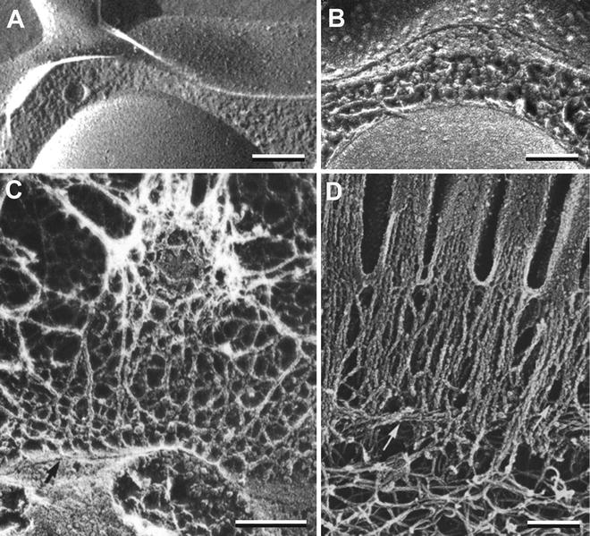
Fig. 6
Platinum replicas of rapidly frozen specimens prepared with various degrees of ice sublimation (etching). (a) A secretory granule just under the plasma membrane of a mast cell. Note that cytoplasmic and extracellular ice has not been etched. (b) A similar specimen in which moderate etching reveals a dense array of microfilaments in the cytoplasm and the true extracellular surface of the plasma membrane. (c) The sea urchin egg surface is decorated with a fish net-like vitelline layer to which sperm bind. All extracellular matrix structures above the fracture line (arrow) were exposed by 5 min of etching at −90 °C using the QF-DE-RS technique. (d) The apical cytoskeleton of an intestinal epithelial cell as visualized by the QF-DE-RS method. Bundles of microfilaments that form the core structure of microvilli meet the terminal web of filaments in the apical cytoplasm. Scale bars = 0.1 μm. (a) is reproduced from Chandler and Heuser [33], with the permission of the Rockefeller University Press.); (b) is reproduced from Chandler and Roberson [67]; (c) is reproduced from Chandler and Heuser [35], with the permission of the Rockefeller University Press; (d) is reproduced from Hirokawa and Heuser [38], with the permission of the Rockefeller University Press
1.2.4 Freeze Drying of Cell Fragments
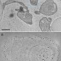
Cell fragments adhering to a glass or mica surface can be freeze dried by extensive sublimation of ice carried out for long periods of time (10 min), at relatively high temperatures (−85 to −90 °C) in a freeze fracture unit at high vacuum. Cell fragments are typically produced by cell adhesion to a surface then the cell sheared open by a stream of buffer under pressure. Cell adhesion may be natural as in the case of epithelial or migrating cells, or may be induced by plating cells on a polylysine coated glass, plastic or mica surface [40, 41]. This approach is particularly useful in visualizing events at the cell cortex such as exocytosis, endocytosis and cytoskeletal reorganization [42–44]. A typical preparation—the true inner surface of a neutrophil plasma membrane—is shown in Fig. 7a. Seen attached to the plasma membrane are a number of microfilament clusters as well as clathrin baskets marking endocytic vesicles in various stages of budding.
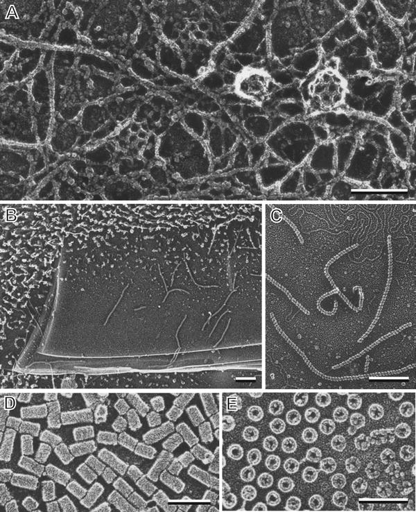
Fig. 7
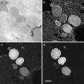
Deep etching and freeze drying of cell cortices and macromolecules. (a) Inside surface of a rabbit neutrophil plasma membrane prepared by freeze drying. Microfilament networks surround numerous clathrin baskets attached to the membrane. (b) Deep etching of mica flakes on which is adsorbed Rec A, a DNA binding protein from Escherichia coli. (c) Linear RecA polymers on mica at higher magnification. (d) and (e) Hemocyanin, a blood protein from horseshoe crab is seen as a cylinder. Cross-fractured hemocyanin cylinders adhering to the mica surface end-on reveal a hollow interior. (b) and (c) are reproduced from Heuser [46] with the permission from Alan R. Liss Inc. and Wiley Periodicals, Inc.; (d) and (e) are reproduced from Heuser [45] with the permission from Elsevier. Scale bars = 0.1 μm
1.2.5 Deep Etching and Freeze Drying of Macromolecules
Macromolecules, generally greater than 50 kDa, can be purified and adhered to the surface of mica flakes and then quick frozen and either deeply etched or freeze dried to reveal their architecture. Fixation or cryoprotection is not required providing the proteins adsorbed to the mica flakes are rapidly frozen usually by a cold metal block procedure [45, 46]. Optimal images are obtained by rotary shadowing with platinum at 25° although lower angles are sometimes used. This procedure also works well for macromolecular assemblies such as vesicle coat proteins and viruses [47, 48]. Classic examples of quick frozen and freeze dried proteins and molecular assemblies are shown in Fig. 7a. Low magnification images reveal the mica flake substrate (see Fig. 7b) with adherent macromolecules—in this case polymerized Rec A, a DNA binding protein isolated from Escherichia coli. At high magnifications, individual Rec A polymers can be seen to be a linear chain of monomers (see Fig. 7c). Using horseshoe crab hemocyanin as a test specimen, Heuser demonstrated this protein to be a hollow cylinder when one compares proteins adsorbed lengthwise to the mica (see Fig. 7d) with proteins that stand “stump-like” on the mica surface after being cross-fractured at a variety of levels (see Fig. 7e). This method was developed and perfected by Heuser whose review articles [45, 46] discuss the details of mica preparation for optimal protein absorption, a step critical to its success.
1.2.6 Freeze Fracture Cytochemistry and Immunocytochemistry
Traditional cytochemistry involves the localization of enzymatic activities of tissues in situ by supplying a substrate that can be turned into a product capable of being imaged in the electron microscope. Classic examples include the localization of acid phosphatases to lysosomes by their production of phosphate which is then precipitated with lead or cerium and converted to a sulfide which is imaged as an electron dense deposit. Similar cytochemical procedures have been used successfully in tissue that is subsequently processed by freeze fracture and replicated [49]. Of more widespread use are reagents that complex with the tissue constituent of choice to produce large particles or topological features in the replica itself. A common example of this is the use of filipin or tomatine, sterols that bind to cholesterol in membranes to form large complexes easily seen in a freeze fracture replica (see Fig. 8a). This technique, pioneered by Friend and colleagues [50, 51], has been used extensively to demonstrate cholesterol-containing domains in membranes [52].
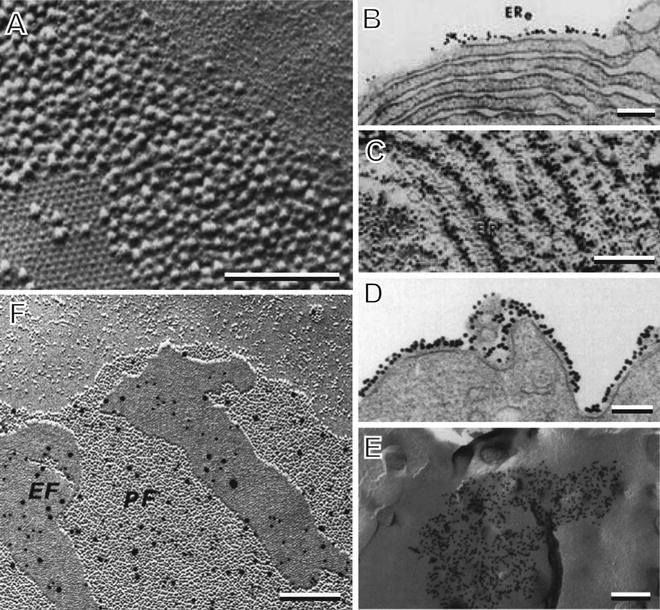
Fig. 8
Freeze fracture cytochemistry and immunocytochemistry. (a) Filipin–cholesterol complexes seen in the plasma membrane of a guinea pig sperm. (b) Colloidal gold-Concanavalin A labeling of glycoproteins in freeze fractured endoplasmic reticulum membranes of pancreatic acinar cells. (c) Colloidal gold labeling in a platinum replica of an equivalent endoplasmic reticulum specimen prepared by the “fracture-label” method. (d) Thin section of a lymphocyte plasma membrane with colloidal gold labeling of HLA I antigens during capping. (e) Distribution of colloidal gold-labeled HLA I as seen in a P-face replica of the capped lymphocyte plasma membrane as prepared by the “label fracture” method. (f) Double immunogold labeling of connexin isotypes 26 (10 nm gold) and 32 (20 nm gold) at the gap junctions of a liver cell in a replica prepared by the “SDS freeze-fracture replica immuno-labeling” (FRIL) method. (a) is reprinted from Elias et al. [51], with the permission of SAGE Publications; (b) and (c) are reproduced from Pinto da Silva [53], with the permission from the Rockefeller University Press; (d) and (e) are reprinted from Pavan et al. [56], with the permission of SAGE Publications; (f) is reproduced from Fujimoto [59] by permission from the Journal of Cell Science. Scale bars = 0.25 μm
Of greater impact has been the ability to use immunocytochemistry in conjunction with freeze fracture, first achieved by Pedro Pinto da Silva in a process called “fracture-label” [53, 54]. In this method, tissues were fixed, rapidly frozen and fractured and only then thawed in aldehyde fixative, washed and subjected to colloidal gold immunolabeling. Finally the labeled fracture surfaces could be visualized either by embedding in epoxy resin and sectioning or by critical point drying followed by platinum–carbon shadowing either in a freeze fracture unit or in a standard vacuum evaporator [53, 54]. As shown in Fig. 8b, the colloidal gold markers are easily seen on fracture surfaces in sectioned material while in platinum replicas, the markers are visible but the preservation of the fracture faces is compromised by both aldehyde fixation and dehydration during critical point drying (see Fig. 8c). Subsequently, Pinto da Silva modified this procedure to one of “label-fracture” in which the tissue, usually a cell suspension, was carried through immunocytochemical labeling first and then frozen, fractured and shadowed with platinum-carbon in a freeze fracture unit [55, 56]. Next, the specimen was washed, mounted on a grid and observed by TEM directly without having cleaned away the tissue. Although views of many areas of the replicated surface were obliterated by the presence of tissue, regions containing E faces with attached label were visible since the biological material present was limited to that of a single, transparent monolayer. For example, in studies of antigen-induced capping of lymphocytes, aggregates of colloidal gold-labeled HLA I proteins were easily seen in sections (see Fig. 8d). Specimens processed in parallel using label-fracture methods revealed remarkable replicas of “E” fracture faces with colloidal gold labeling that defined the extent of the cap in two dimensions (see Fig. 8e).
The label-fracture approach led naturally to the “fracture-flip” method also developed by Pinto da Silva [57, 58] and the “SDS freeze-fracture replica immuno-labeling” (FRIL) method developed by Fujimoto [59, 60]. The FRIL method, in common use today, is an extension of the label-fracture method. The only additional step is that the labeled, fractured and replicated tissue is cleaned with sodium dodecyl sulfate and water before viewing, thereby solubilizing most of the tissue and allowing clear visualization of both E and P fracture faces. As shown in Fig. 8f, the colloidal gold markers identify connexins 26 and 32 within the gap junctions of mouse liver cells [60]. The combination of well preserved structure and clean fracture faces in these replicas make this the current method of choice for freeze fracture immunocytochemistry.
1.2.7 Stereology and Tomography of Freeze Fracture Replicas
Fracture faces of tissues are three dimensional with topology in the optical axis that is easily perceived by shadowing of this surface at an angle. The perception of depth can be direct by using stereology in which two images of the replica taken at different angles are used to form a stereo pair, each image projected to a different eye by use of appropriate optics. This requires a goniometer stage to tilt the specimen typically at ±6° to 12° from the optical axis as images are recorded. Detailed methods for doing this have been described by Heuser in several articles [61, 62]. As an example, the stereo pair of images in Fig. 9 reveals the topology of the vitelline layer on the sea urchin egg surface in a specimen that was quick-frozen, deep-etched and rotary-shadowed [63]. The depth afforded in this stereo pair reveals numerous fibrous polymers connecting the tips of microvilli as well as a sheet of networked fibers draped over the egg surface and connected by short anchoring posts to the plasma membrane. Below the fracture line (arrow), the etched “P” face of the plasma membrane reveals the stumps of several microvilli that have been cleaved.
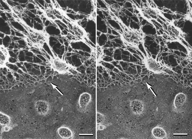
Fig. 9
Stereo pair micrograph of the surface of a sea urchin egg showing an array of microvilli covered with the net-like vitelline layer. Prior to etching ice covered the specimen above the fracture line (arrow). The replica was prepared by the QF-DE-RS technique. The image is reproduced from Larabell and Chandler [37], with the permission from Alan R. Liss Inc. and Wiley Periodicals, Inc. Scale bar = 0.1 μm
The depth inherent in a replica can be quantitatively examined using tomography methods in which a film-supported replica is rotated through a large angular sweep with images being acquired at 1° intervals. As described by Morone et al. [64, 65], one can use appropriate software and image information to reconstruct a three-dimensional model of the replica with calibrated dimensions. Although most studies require only the qualitative depth perception that stereology provides, any quantitative studies of depth might best use the tomographic approach.
2 Materials
2.1 Standard Freeze Fracture Technique
1.
Glutaraldehyde, 4–10 % EM grade in sealed vials.
2.
Phosphate- or Hepes-buffered saline. Concentration and pH should be optimal for the specimen as determined by previous literature or experience.
3.
Glycerol, reagent grade.
4.
Liquid nitrogen. Usually obtained from specialty cryogenics suppliers.
5.
Compressed propane. Canisters used for camping stoves are most convenient.
6.
Acetone, reagent grade. For cleaning specimen carriers.
7.
Ethanol, UPS grade. For the alcohol lamp.
8.
Transmission Electron Microscope.
9.
Freeze fracture unit. The Balzers 400D freeze fracture unit is assumed in this protocol but other equivalent units such as the Leica EM BAF 060 or JEOL JFD II may be used.
10.
Large liquid nitrogen Dewar (160–200 l preferably) with valving for both liquid and gas removal.
11.
Compressed nitrogen gas tank with pressure regulator.
12.
Plunge freezing device having well for liquid nitrogen-cooled liquid propane. Can be commercial or custom made.
13.
Chemical hood certified for explosive gases.
14.
Small Dewer with basket for temporary storage of frozen specimens.
15.
Liquid nitrogen Dewar (25–40 l capacity) for storage of frozen specimens.
16.
Balzers brass specimen table with specimen spring clamp, asymmetric cam lock down, and spring clamp opening tool.
17.
Balzers brass specimen carriers, 3 mm diameter, in welled hat configuration.
18.
Tweezers, fine curved. Five pair.
19.
Small tabletop stand with metal bracket for mounting the specimen table. Used to lockdown specimen table during cleaning or specimen retrieval.
20.
Styrofoam or insulated container with metal stand. For immersion of specimen table in liquid nitrogen while loading specimen carriers.
21.
Short specimen table transfer rod.
22.
Long specimen table insertion/transfer rod. To be used in conjunction with the counterflow loading port.
23.
Consumables for carbon and platinum deposition:
(a)
Coiled filaments for the electron beam guns.
(b)
Carbon rods, 3 mm dia., for the carbon evaporation gun.
(c)
Carbon rods, 2 mm dia. with recessed tips, for the platinum evaporation gun.
(d)
Platinum slugs. These slip into the recessed tips of the above carbon rods.
(e)
“Scotch-Brite” cleaning pads. For cleaning metal surfaces of electron beam guns and specimen tables after use.
(f)
Emery paper, fine. For leveling the ends of carbon rods.
24.
Woven cotton or nylon gloves. For use while handling components in the vacuum chamber such as the electron beam guns.
25.
Quartz crystal monitor.
26.
Quartz crystal monitor disks.
27.
Centering jig for filament alignment.
28.
 Microwave-Assisted Processing and Embedding for Transmission Electron Microscopy
 Electron Microscopy of Microtubule Cytoskeleton Assembly In Vitro
 Biological Applications of Energy-Filtered TEM
 Biological Applications of Phase-Contrast Electron Microscopy
 Correlative Light and Electron Microscopy Using Immunolabeled Sections
 X-Ray Microanalysis in the Scanning Electron Microscope


Small screw driver for assembly and disassembly of electron beam guns.
Related posts:
Microwave-Assisted Processing and Embedding for Transmission Electron Microscopy
Electron Microscopy of Microtubule Cytoskeleton Assembly In Vitro
Biological Applications of Energy-Filtered TEM
Biological Applications of Phase-Contrast Electron Microscopy
Correlative Light and Electron Microscopy Using Immunolabeled Sections
Stay updated, free articles. Join our Telegram channel
Full access? Get Clinical Tree
