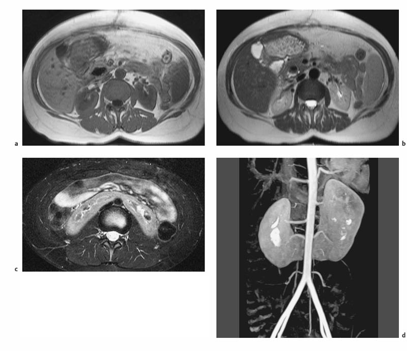
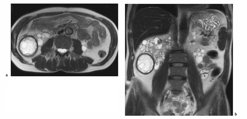
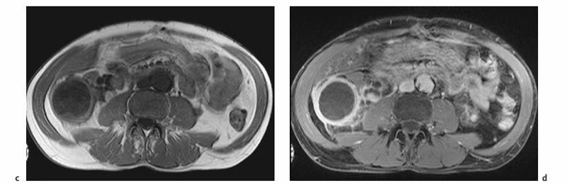
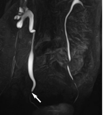
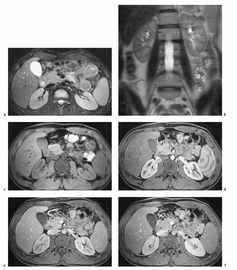
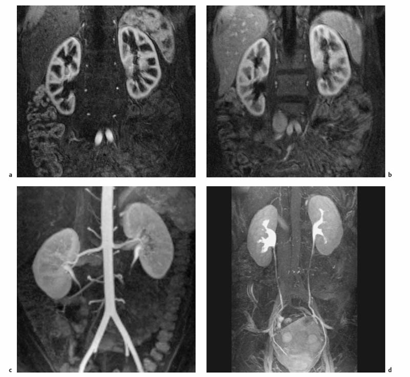
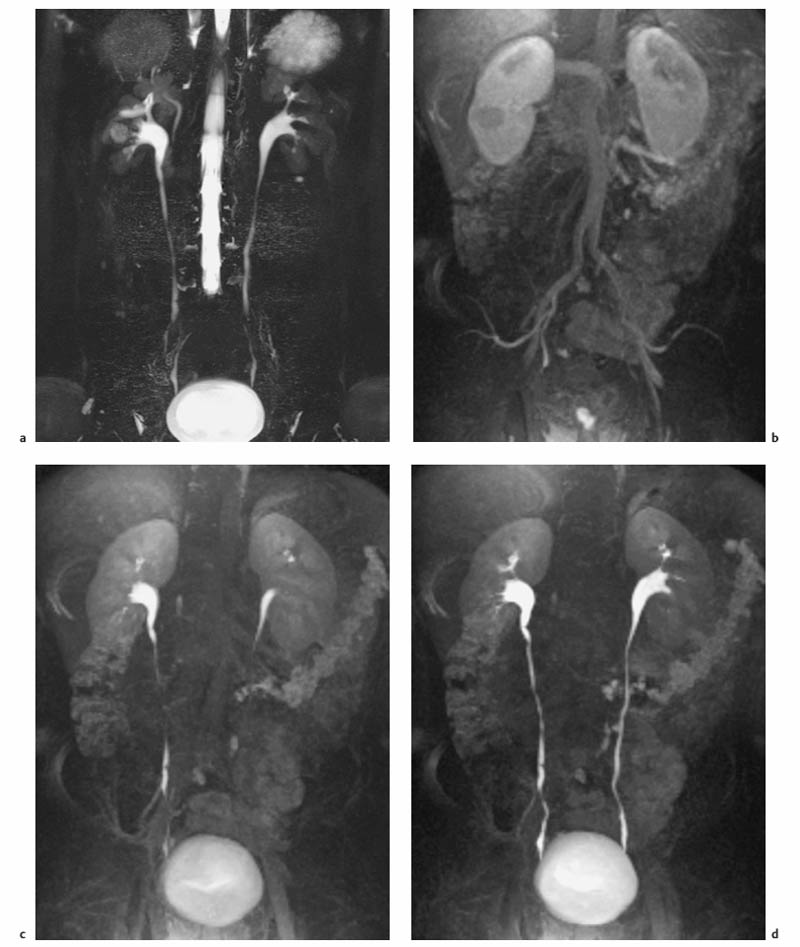
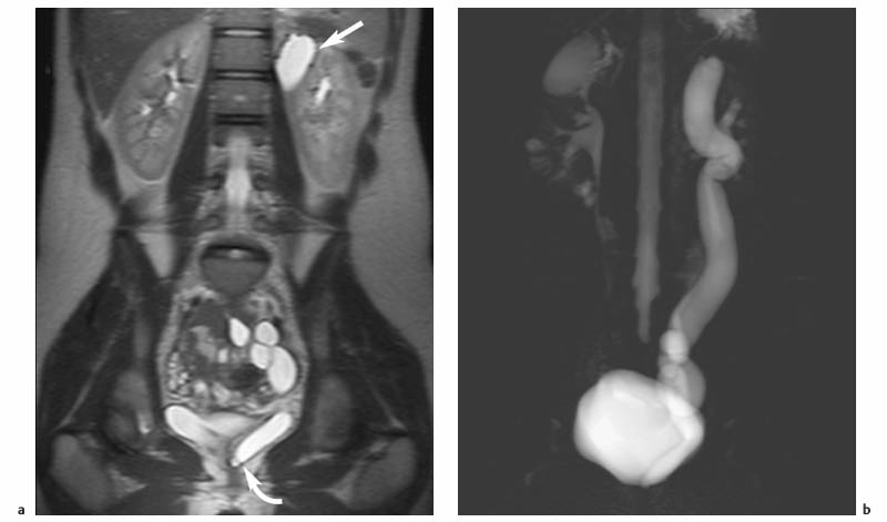
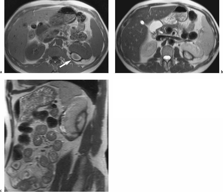
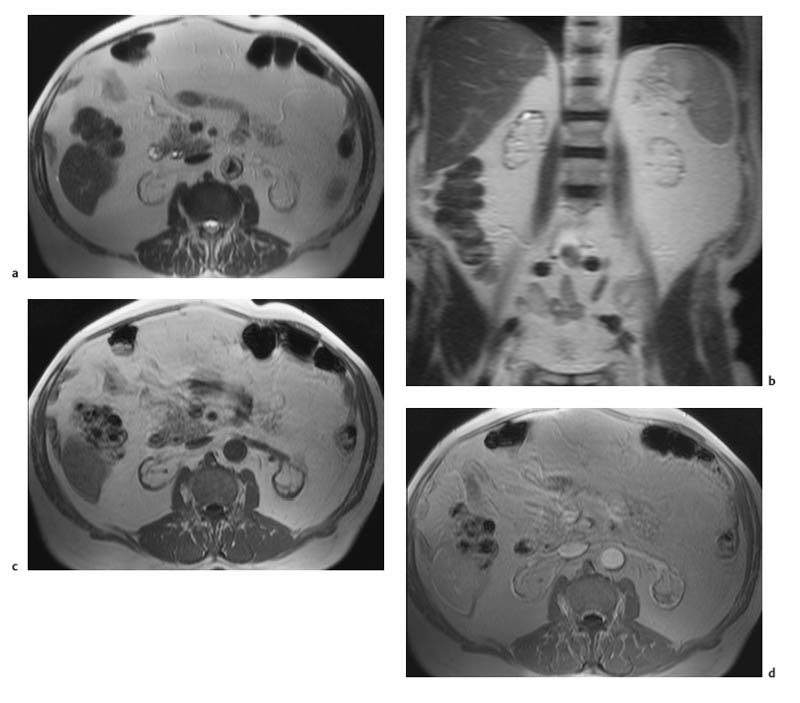
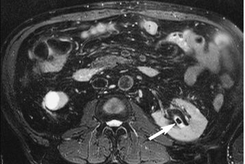
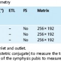
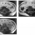
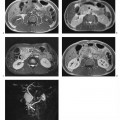
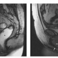
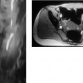
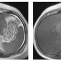
7 The Kidneys and Upper Urinary Tract MRI no longer merely provides morphologic information on the kidneys and ureters but has evolved into a versatile imaging technique for use in patients with renal or ureteral tumors and for detailed assessment of the renal vasculature. Moreover, it also allows an insight into the excretory function of the kidneys. A comprehensive MRI protocol with use of intravenous contrast medium combines multiplanar soft-tissue evaluation and qualitative assessment of tissue perfusion with arterial and venous MR angiography (MRA) and also includes excretory MR urography (MRU). In particular, MRI can serve as a “one-stop shop” modality, replacing the classic combination of cross-sectional imaging, intravenous urogram, and conventional angiography in the preoperative evaluation of renal and ureteral tumors. Such an MRI protocol can also be used for assessing patients with renal and ureteral anomalies. Two notable advantages–the absence of radiation exposure and the lower nephrotoxicity of MRI due to the need for smaller amounts of contrast material–make this method suitable for younger patients and also for patients with nonmalignant disease. MRI yields the same diagnostic information as CT in patients who have reduced kidney function or do not tolerate iodine-based contrast media. The only disadvantage of MRI compared with CT is its poor visualization of urinary calculi, although it nevertheless allows excellent evaluation of the urinary obstruction secondary to urolithiasis. Thanks to its technical versatility, MRI enables evaluation of the renal parenchyma, the arteriovenous system, and the renal collecting system and ureters, resulting in a broad spectrum of indications for renal MRI: Renal MRI is performed with the patient in a comfortable supine position; a knee support can be offered to improve comfort. As renal MRI regularly comprises sequences in the coronal plane with a left-to-right phase-encoding direction, the patient’s arms may cause wraparound artifacts. Such artifacts can be avoided by placing cushions underneath the arms to elevate them above kidney level.1 The arms must not be placed on the patient’s abdomen as this will cause wraparound on axial images. Patients are carefully instructed to breathe shallowly and regularly during acquisition of non-breath-hold sequences to avoid excessive breathing motion of the abdominal wall. Careful breathing instructions are also necessary if respiratory-triggered acquisition is planned. Finally, it is important that the breathing commands to be given for breath-hold imaging are explained beforehand. For contrast-enhanced imaging, a flexible cannula should be placed, ideally in an antecubital vein, before positioning the patient in the magnet, and connected to a saline-filled syringe or, if available, an MR-compatible injection pump via extension tubing. Body or torso phased-array coils for abdominal imaging are available from nearly all manufacturers and should be used to improve the signal-to-noise ratio (SNR), especially when fast pulse sequences are acquired2. Phased-array coils (with 4– elements) are also needed to employ parallel imaging techniques such as sensitivity encoding (SENSE), which can be used to shorten scan time or to acquire higher-resolution images with both T1w and T2w sequences.3–5 However, this gain may come with a penalty in SNR.6 The renal MRI protocol can be tailored to different clinical indications (Table 7.1). The basic protocol for soft-tissue evaluation comprises T2w and T1w sequences in multiple planes and should include a T1w sequence acquired with in-phase (IP) and opposed-phase (OP) echo times (TEs) (see Chapter 1). Static MRU of the renal collecting systems and ureters is performed by acquiring a heavily T2w sequence in the coronal plane (comparable to that employed for MRCP; see Chapter 2). The contrast-enhanced series is acquired using a coronal 3D MRA sequence and includes an arterial and venous phase for vascular assessment (see Chapter 15). The protocol is completed by acquiring a delayed axial T1w sequence identical to the corresponding precontrast sequence. To obtain an excretory MR urogram, the 3D MRA sequence is repeated 5 min and 10 min after intravenous contrast injection as well as at later times if contrast medium excretion is delayed. Details of the sequences used for the three main portions of the renal MRI protocol are summarized in Table 7.2. Precontrast Imaging At our institution, we acquire a localizer followed by a T2w single-shot TSE sequence (e. g., HASTE) in axial, sagittal, and coronal planes. The sagittal images are used to angle the coronal sequence to the long axis of the kidney. An additional respiratory-triggered, fat-suppressed high-resolution T2w TSE sequence should be acquired in patients with a small tumor7 (see “T2-Weighted Imaging” in Chapter 1) (Fig. 7.1). An axial 2D T1w GRE sequence (e. g., 2D FLASH) acquired with IP and OP TEs (see Table 1.3) is required for identification of lipid-containing renal tumors such as angiomyolipoma.1 If available, IP and OP images can be acquired using a double-echo sequence. The 2D T1w GRE sequence can be replaced or supplemented by an axial or coronal fat-suppressed 3D GRE sequence (e. g., VIBE) (Fig. 7.1). The 3D GRE sequence improves spatial resolution because thinner slices can be acquired compared with its 2D counterpart; however, this is achieved at the expense of soft-tissue contrast on non-enhanced images. Contrast-Enhanced Imaging If contrast-enhanced MR images are primarily needed for optimal soft-tissue visualization, and vessel contrast is less important, an axial or coronal 3D GRE sequence emphasizing soft tissue (e. g., VIBE) should be used. Dynamic contrast-enhanced imaging is performed during the arterial/cortical phase (15 s), venous/corticomedullary phase (1 min), and early excretory phase (at ca. 3 min) (Fig. 7.1). If the contrast-enhanced series is performed for vascular evaluation, a coronal 3D MRA sequence is acquired with a field of view completely including the aorta and vena cava as well as the kidneys. The sequence is angled to the longitudinal axis of the kidney using the sagittal T2w precontrast sequence (see above). Following a timing run, the MRA sequence is acquired during the arterial phase and 1 min after bolus injection of the contrast medium (Fig. 7.2). The MRAdataset serves to generate multiplanar reformations (MPR) or maximum intensity projections (MIP) of the target vessels and at the same time provides detailed information on renal perfusion. Finally, the precontrast 2D or 3D GRE sequence is repeated to obtain delayed images emphasizing soft tissues. To obtain an excretory MR urogram, the 3D MRA sequence is repeated ca. 10 min after contrast injection (Fig. 7.2). This can be performed in one of two ways:8,9 T2w Static MR Urography. This technique involves the use of heavily T2-weighted TSE sequences initially developed for MRCP and yielding images on which stagnant fluid is depicted with a bright signal (hydrography). The slices are acquired in coronal planes angled to the kidneys and ureters using a sagittal localizer. One way to obtain a static MR urogram is to acquire thick slabs in multiple projections during short breath-holds of ca. 3–5 s using a single-shot T2w TSE sequence (e. g., HASTE, RARE). These have limited detail resolution and merely serve to gain a quick overview or as an additional planning scan. Better image quality is obtained by acquiring multiple thin slices during a 20-s breath-hold using a T2w single-shot TSE sequence. The thin-slice datasets can be postprocessed using MPR or MIP algorithms. Image quality can be further improved by respiratory-triggered acquisition of T2w 3D TSE sequences;10 however, the scan time is several minutes (Fig. 7.3). Static MR urograms provide no functional information but allow evaluation of the collecting system in patients with no or only little excretory function. T1w Excretory MR Urography. This technique is based on the renal excretion of an intravenously injected MR contrast medium and its detection with a heavily T1-weighted coronal 3D GRE sequence identical to that employed for MRA. Images are acquired at similar time points as with conventional intravenous urography (Fig. 7.3). However, adequate contrast filling may be delayed in patients with severely dilated collecting systems and ureters or reduced excretory function. This limits the use of excretory MRU in the routine clinical setting as it may not be feasible to repeat imaging at later time points. Both techniques of MRU can be performed with administration of a diuretic (0.05–0.1 mg furosemide) for dilatation and improved visualization of the collecting systems and ureters. Furosemide improves overall image quality of excretory MRU by enhancing the elimination of the contrast medium and its mixing with the urine.8 Renal MRI including MRA and MRU is performed using a nonspecific Gd-based contrast medium such as Gd-DTPA (Magnevist), gadoteridol (Prohance), gadobutrol (Gadovist), or Gd-DOTA(Dotarem). These are only examples, and contrast media development is a very dynamic field, which is why radiologists should always check the most up-to-date information regarding approval status in their own country before administering any intravenous contrast medium. The nonspecific Gd-based agents rapidly distribute in the extracellular space after intravenous injection and are eliminated via the kidneys. Their elimination is thus comparable to that of iodine-based X-ray contrast media. Soft-tissue evaluation and MRU are performed with administration of the standard dose of 0.1 mmol Gd per kg body weight. A dose of 0.2 mmol/kg Gd is administered if the protocol also includes MRA. Especially when the higher dose is injected, the high urinary concentration can cause signal voids in the collecting system on delayed images. Note that static T2w MRU cannot be performed after intravenous contrast injection. Patients with severely compromised renal function have a small risk of developing nephrogenic systemic fibrosis (NSF) after intravenous injection of Gd-based contrast medium. Radiologists should therefore use such agents with great caution in these patients, taking into account the most recent official guidelines and manufacturers’ recommendations. In general, patients with severe renal impairment should not receive Gd doses exceeding 0.1 mmol/kg and should not undergo repeated contrast-enhanced MRI at short intervals. The kidneys are paired organs located in the lumbar fossae in the retroperitoneum. Grossly, the renal parenchyma is composed of the renal medulla and the renal cortex. With MRI, the corticomedullary differentiation is best appreciated on unenhanced and early contrast-enhanced T1w images (Fig. 7.1). The kidney has a firm capsule, which is not usually seen on imaging, and an outer adipose capsule (or perirenal fat). The kidney, adrenal gland, and adipose capsule are enclosed by the renal fascia. The fascia is most conspicuous on MR images when it is thickened, e. g., due to inflammation.11 Anomalies An ectopic kidney, such as a pelvic kidney, results from failure of the developing kidney to ascend to its normal position. The multiplanar capability of MRI, in particular the coronal plane, is helpful for defining the exact position of an ectopic kidney, and an MRA sequence can be performed to assess its blood supply. An ectopic kidney is typically supplied by aberrant arteries arising from the aorta or pelvic arteries. A horseshoe kidney (Fig. 7.4) is the fusion of the inferior poles of the two kidneys by an isthmus of fibrous tissue or renal parenchyma. An ectopic or horseshoe kidney typically has normal function but is more susceptible to traumatic injury because it is less well protected than a kidney in normal location.12 Ectopic insertion of a ureter results from abnormal migration of a ureteral bud. An ectopic ureter opening into the bladder typically inserts lower than a normal ureter. Other ectopic insertions are the urethra, the vagina, and the uterus in females and the posterior urethra, the seminal vesicles, the ejaculatory duct, and the vas deferens in males. An ectopic ureter inserting below the continence mechanism causes urinary incontinence, which is the case in ca. 50% of ectopic ureters. About 70% of ectopic ureteral openings are associated with a duplex kidney and a bifid ureter.13 It is important to identify such anomalies as early as possible; however, the diagnosis is sometimes delayed until adulthood. MRI with the option of static T2w urography is the ideal imaging modality for this purpose because it will also depict a nonfunctioning or poorly functioning renal moiety (Fig. 7.5).14 Fig. 7.4a–d Horseshoe kidney without associated anomalies. a, b Axial T1w (a) and T2w (b) images through the renal hilum. c Axial fat-suppressed T2w TSE im age acquired through the parenchymal isthmus at a lower level. d MIP reconstruction of a contrastenhanced MRA showing the parenchymal vessels and beginning excretion of the contrast medium (from test bolus injection) into the renal caliceal system. Trauma Abdominal trauma such as that associated with traffic accidents often causes renal contusion or renal vascular injury. Kidneys with prior damage (e. g., due to hydronephrosis) or in an ectopic position are more susceptible to traumatic injury. The role of MRI in emergencies is limited because monitoring of severely injured patients is generally not possible. Multislice CT is the method of choice in acute situations because it enables simultaneous evaluation of the renal parenchyma and renal vessels. Apart from accidents, intra- or perirenal hematoma can be caused by extracorporeal shockwave lithotripsy, diagnostic puncture, clotting disorders, arteriovenous malformations, renal artery aneurysms, renal cell carcinoma, or rupture of a renal cyst. In this setting, MRI will detect small hemorrhage and contributes to the identification of the underlying cause and is also useful for follow-up. The T1 and T2 signal intensities of hemorrhagic lesions vary with the age of the hemorrhage (Fig. 7.6). Perirenal hematoma must be differentiated from urinoma, which—just like urine in the bladder—has low signal intensity on T1w images and high signal intensity on T2w images. If injury of the pelvicaliceal system is suspected in the acute setting, a postcontrast T1w series will demonstrate leakage of contrast medium and thereby of urine (see Figs. 7.33 and 7.34). Inflammation/Abscess Imaging modalities are typically used in patients with acute pyelonephritis to evaluate for complications such as pyonephrosis or abscess. Renal inflammation is seen on MRI as swelling of the kidney, altered signal intensities due to accompanying edema, blurring of renal contours, and loss of corticomedullary differentiation. There may be inflammatory stranding of perirenal fat and thickening of perirenal fasciae, best appreciated on unenhanced T1w images. Severe inflammation may be associated with focal perfusion defects on contrast-enhanced images. A full-blown abscess is a lesion with a central fluid collection of high T2 signal intensity surrounded by a wall that will enhance after contrast administration.15 Both solitary renal cysts and cysts in patients with polycstic kidney disease can become infected. An infected cyst resembles an abscess with a central fluid signal surrounded by a thickened wall showing intense enhancement on postcontrast T1w images (Fig. 7.7).16 Renal atrophy is usually due to chronic inflammation. MRI may be indicated for example if a tumor is suspected. Atrophied kidneys are only seen otherwise on MRI if the examination is performed for other purposes (Fig. 7.8). Fig. 7.7a–d Infected renal cyst in the right kidney in bilateral cystic kidney disease. a, b Axial (a) and coronal (b) breath-hold T2w TSE images. c Precontrast axial breath-hold T1w GRE image. d Fat-suppressed axial breath-hold T1w GRE image after IV contrast injection. The fluid in the infected cyst appears homogeneous on the unenhanced images and has a thickened wall, which enhances intensely on the postcontrast image. Fig. 7.10 Urinary obstruction due to a stone in the right ureter. MIP image of excretory MRU performed with a coronal 3D GRE sequence ca. 10 min after IV contrast injection. Dilatation of the right collecting systemand ureter down to the level of the stone at the iliac vessel crossing (arrow). Urinary Obstruction Dilatation of the renal collecting systems and ureters occurs secondary to acute or chronic obstruction. The most common causes of acute obstruction are stones or blood clots, pregnancy, and ureteral edema developing after iatrogenic instrumentation, e. g., for stone extraction (Figs. 7.9 and 7.10). Chronic obstruction can be congenital or acquired. Causes of acquired obstruction are tumors of the urinary bladder, prostate, uterine cervix, or retroperitoneum, ureteral strictures, and benign prostatic hyperplasia. If the underlying cause cannot be identified by ultrasound, MRU performed as part of a renal soft tissue and vascular MRI protocol should be preferred to conventional intravenous urography or CT. The absence of radiation exposure is especially important in younger patients. Renal Cysts Simple cysts (Fig. 7.11), the most common renal lesions, are found in ca. 50 % of adults after the age of 50. They are typically benign and detected incidentally. On MRI they are seen as sharply demarcated lesions of low T1 signal intensity and high T2 signal intensity which do not enhance on T1w images following intravenous contrast medium administration.1 Parenchymal, cortical, and parapelvic renal cysts are distinguished by location. Parapelvic cysts can mimic dilatation of the pelvicaliceal system on ultrasound and unenhanced T1w and T2w MR images. Unclear cases can be resolved by a contrast-enhanced T1w study including an excretory MR urogram (Fig. 7.12). Complicated cysts
M. Taupitz and R. A. Kubik-Huch
Introduction
Indications
Imaging Technique
Coils
Pulse Sequences
Contrast Media
MRI Appearance of Normal Anatomy
MRI Appearance of Pathologic Entities
Benign Conditions
![]()
Stay updated, free articles. Join our Telegram channel

Full access? Get Clinical Tree


