(1)
Central Facility for Electron Microscopy, Ulm University, Ulm, Germany
(2)
Institute of Virology, University Medical Center Ulm, Ulm, Germany
(3)
Institute of Analytical and Bioanalytical Chemistry, Ulm University, Ulm, Germany
(4)
Department of Infectious Diseases, Virology, University of Heidelberg, Heidelberg, Germany
Abstract
In this chapter we describe three different approaches for three-dimensional imaging of electron microscopic samples: serial sectioning transmission electron microscopy (TEM), scanning transmission electron microscopy (STEM) tomography, and focused ion beam/scanning electron microscopy (FIB/SEM) tomography. With these methods, relatively large volumes of resin-embedded biological structures can be analyzed at resolutions of a few nm within a reasonable expenditure of time. The traditional method is serial sectioning and imaging the same area in all sections. Another method is TEM tomography that involves tilting a section in the electron beam and then reconstruction of the volume by back projection of the images. When the scanning transmission (STEM) mode is used, thicker sections (up to 1 μm) can be analyzed. The third approach presented here is focused ion beam/scanning electron microscopy (FIB/SEM) tomography, in which a sample is repeatedly milled with a focused ion beam (FIB) and each newly produced block face is imaged with the scanning electron microscope (SEM). This process can be repeated ad libitum in arbitrary small increments allowing 3D analysis of relatively large volumes such as eukaryotic cells. We show that resolution of this approach is considerably improved when the secondary electron signal is used. However, the most important prerequisite for three-dimensional imaging is good specimen preparation. For all three imaging methods, cryo-fixed (high-pressure frozen) and freeze-substituted samples have been used.
Key words
High-pressure freezingSapphire discsFreeze substitutionScanning transmission electron microscopySerial sectioningFIB/SEM tomography1 Introduction
Electron microscopic images are two-dimensional (2D) projections of three-dimensional (3D) samples. Information is thereby lost for two reasons. Firstly, the 3D structure of a 2D projection is not defined; a circle can result from the projection of a sphere or of a cylinder. Secondly, when a thin section is imaged, only the structures (organelles, membranes) located in the section plane are visible. This does not represent a problem, as long as the object of interest is isotropic. Adherent (epithelial) cells, however, are very anisotropic. They often come in the shape of a fried egg sunny-side up, which means that the structures in Z-direction (perpendicular to the substrate) are very different from the structures in X– and Y-directions (parallel to the substrate). In anisotropic cells, therefore, the distribution of organelles, cytoskeletal elements, or viral particles can only be quantitatively analyzed when the cell is imaged in 3D. There are different methods for 3D analysis in electron microscopy, and they all involve reconstruction of a 3D model from a number of 2D projections. For this chapter we describe serial sectioning TEM, STEM tomography, and FIB/SEM tomography. The most important prerequisite for three-dimensional imaging is good specimen preparation. For all these three imaging methods, cryo-fixed (high-pressure frozen) and freeze-substituted samples are used. During freeze substitution, the biological structures are stained with the heavy metals osmium or uranium (on-section staining is not necessary). The contrast, therefore, is not produced by the biological structure but by the stain. This ultimately limits the resolution of these methods to the accuracy of the staining, which is roughly a few nm. This limitation is a disadvantage compared to cryo-TEM, where unstained samples are imaged in the frozen-hydrated state and the contrast is formed by the biological material itself [1, 2]. On the other hand, freeze-substituted and resin-embedded samples are very stable in the electron beam, in contrast to the beam-sensitive frozen-hydrated samples. They can, therefore, be easily imaged at room temperature using standard electron microscopes. In the following sections we briefly describe specimen preparation and the imaging approaches and also some recent technical improvements. The methods discussed in this chapter are especially suitable for relatively large volumes, e.g., whole cells or large portions of cells. The pros and cons of the abovementioned three different electron microscopy methods for studying 3D of cells are listed in Table 1.
Table 1
The pros and cons of different EM methods for studying 3D of cells
EM methods | Serial sectioning TEM | STEM tomography | FIB/SEM tomography |
|---|---|---|---|
Resolution | Good resolution in X and Y, poor resolution in Z (limited by section thickness) | Good resolution in X and Y, reasonable resolution in Z | Good resolution in X, Y and Z (isotropic resolution possible) |
Volumes | Large volumes (whole cells) can be imaged in a reasonable period of time (days) | Sample thickness limited to about 1 μm | Large volumes (whole cells) can be imaged in a reasonable period of time (hours) |
Pre-inspection of the area of interest | Possible | Possible | Structures cannot be examined in detail before the destroying milling process is started |
Destructive or nondestructive approach | Nondestructive | Nondestructive | Destructive |
Equipment | No special equipment needed beside microtome and regular TEM | Special and expensive microscopes needed | Special and expensive microscopes needed |
1.1 High-Pressure Freezing
High-pressure freezing is considered the gold standard of immobilizing and fixing cells or tissue pieces [3]. Thereby, samples can be immobilized from a defined physiological state within a few milliseconds. The simultaneous application of a pressure of about 2,000 bar reduces structure-destroying ice-crystal formation [4]. New technical developments regarding high-pressure freezing are used in larger specimen carriers with diameters up to 6 mm for the machines Leica, HPM 100 (Leica Scientific Instruments, Vienna, Austria) and Wohlwend, Compact 2 (Engineering Office M. Wohlwend, Switzerland). In addition, Leunissen and Yi [5] published a self-pressurizing high-pressure freezing method. The basic idea is to use specimen carriers that can withstand the pressures caused by the volume expansion resulting from hexagonal ice-crystal formation. This means there is no space for the hexagonal ice to form. Based on this principle, Leica has manufactured the SPF machine (self-pressure freezer; Leica Scientific Instruments, Vienna, Austria). In this chapter, we use a “conventional” high-pressure freezer and our sapphire-gold sandwiches [6]. We consider this system an ideal for correlative microscopy.
1.2 Freeze Substitution
During freeze substitution, the ice in the frozen specimen is gently substituted by an organic solvent (usually acetone) by warming up the sample from −90 °C to −20 °C or to room temperature over a time period of several hours. Thereby, the fixatives are added to the substitution medium, such as glutaraldehyde, osmium tetroxide, or uranyl acetate to slowly fix the sample. We showed that in some samples the visibility of membranes is improved when the substitution medium contains some water [7, 8]. Our working hypothesis was that the water stabilizes the hydrophilic heads of phospholipids and keeps them in position during substitution. The benefits of using water in the freeze-substitution medium have been debated in recent publications. Whereas the authors generally confirmed a better visibility of membranes, Sobol et al. [9] observed more protein extraction when water was added. This may, however, have been related to the very extended freeze-substitution times used in their study (111 h compared to 19 h in our studies). Regarding correlative fluorescence and electron microscopy, in preliminary studies we observed some retention of GFPs fluorescent signal during the freeze-substitution process [10]. Kukulski et al. [11], however, reported that the retention of the fluorescence proteins’ signal was not improved when water was added to the substitution medium.
1.3 Serial Sectioning
Serial sectioning TEM is still a reliable method to study biological questions such as distribution of organelles (e.g., mitochondria) or of viral particles throughout a whole cell. Standard equipment available in most EM laboratories is sufficient for this method. It, however, requires very good operating skills. The resolution in Z is thereby limited by the section thickness. The amount of data for a given volume is smaller than these in tilt series tomography, which makes data processing much easier. In addition, the method is not destructive (in contrast to FIB/SEM tomography) and the individual sections can be stored, and later used for tilt series tomography, to highlight a detail at higher resolution.
1.4 STEM Tomography
The standard tomography protocol in the transmission electron microscope is to take several images of a sample area at different tilt angles and to reconstruct a 3D model of this area by back projecting the aligned images, a recent review on this aspect is available [12]. For samples stained with heavy metals, using the scanning transmission mode (STEM) of an electron microscope for collection of tomographic datasets is advantageous when compared to regular TEM. In the STEM mode, inelastic scattering does not cause chromatic aberration, since no projective lenses are used, in contrast to regular TEM. Therefore, thicker samples can be imaged. It has been experimentally demonstrated that STEM is superior to TEM and energy-filtered TEM for tomography of stained samples as thick as 1 μm [6, 13, 14]. When using the parallel nanobeam mode in a Titan microscope (FEI, Eindhoven, The Netherlands), the convergence angle can be set as small as 0.6 mrad, resulting in an extremely large depth of focus [15]. This facilitates operation, since even at low magnification and high tilt angles, all areas of the sample are in focus. The tedious dynamic focus mode is therefore not required.
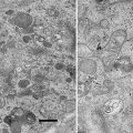
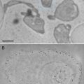
It has been reported that the bright field image is superior to the dark field image when using 1 μm thick sections [13]. This is for geometrical reasons, since the dark field image is more strongly affected by beam broadening than the bright field image. With our recent data (see Figs. 5 and 6), we confirm this observation.
1.5 FIB/SEM Tomography
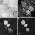
FIB/SEM tomography (focused ion beam/scanning electron microscopy tomography), also called “slice and view,” is a novel approach for the acquisition of tomographic datasets on the basis of surface-SEM ([16–18] and others). In this technique, small portions of a sample are repeatedly milled with an FIB, and each newly produced block face is imaged with the SEM. This process can be repeated ad libitum allowing 3D analysis of relatively large volumes with an edge length of several micrometers [19]. Whereas in standard protocols mainly the (energy filtered) backscattered electron signal is used for image formation, we recently showed that resolution of FIB/SEM tomography can be substantially improved by recording the secondary electron (SE) signal [20]. With this approach macromolecular resolution can be obtained, even at an intermediate accelerating voltage of 5 kV, although the penetration depth of a 5 kV primary beam in a polymer such as Epon is in the range of micrometers [21]. Yet the good resolution can be explained with the specific escape characteristics of secondary electrons. It has been demonstrated recently that even atomic resolution can be achieved on special samples using high-resolution instruments and recording the secondary electron signal [22, 23]. Because of their low energy, secondary electrons can only leave the sample when they are produced at the very surface [24]. Secondary type-one electrons (SEI) escape at the impact point of the primary beam, with a radius in the range of about one nanometer. Hence, they provide the high-resolution information. Unfortunately, secondary type-two electrons (SEII) escape when a backscattered electron (a scattered primary electron) leaves the sample [25, 26]. The radius of the area of escaping SEII electrons is, therefore, in the range of the path of primary electrons in the sample. This corresponds to micrometers at 5 kV accelerating voltage, as explained above. So SEII can cause degradation of resolution. Under certain conditions, however, the resolution-limiting effect of SEII is less pronounced. For example, on a flat surface the signal of SEII is a low-frequency signal and therefore does not significantly disturb the high-frequency SEI signal. Contrast in the SEI signal is highly influenced by surface topography; however, as the FIB-milled block face is very smooth, in this case the contrast is formed by the material composition. Therefore, the characteristic of the image is very similar to a dark field image or a reversed bright field image in TEM mode.
The charging, often a problem in SEM of non-conductive biological samples, was not an issue with the freeze-substituted samples used in this work. The reason may be that adding water to the substitution medium [7] lead to incorporation of relatively high amounts of heavy metals (osmium and uranyl) into the sample. This enhances contrast, and it may also slightly increase electrical conductivity, thereby reducing the charging.
These abovementioned improvements substantially enhance the resolution of FIB/SEM tomography, resulting in images that reveal the same structural details, as that can be seen in the TEM. In addition, several limitations of TEM tomography (limited thickness of the section; problems related to the reconstruction of a volume from tilt series) do not apply for FIB/SEM, making the method easy to apply. FIB/SEM tomography has become a powerful cell biological research tool for 3D structural analysis with macromolecular resolution.
FIB/SEM tomography compares well with STEM tomography and TEM (tomography) in regard to the visibility of small structural details such as the two leaflets of the membrane bilayer. Additionally, considerably larger volumes can be investigated with FIB/SEM tomography. Therefore, we consider it a highly effective method for structural investigations in cell biology. However, it should be kept in mind that during the FIB milling process the imaged area is constantly removed by the FIB immediately after the SEM image has been taken. Therefore, it is not possible to review this area later on, e.g., at higher magnification.
The pros and cons of the abovementioned three different electron microscopy methods for studying 3D of cells are listed in Table 1.
2 Materials
2.1 High-Pressure Freezing
1.
Sapphire discs.
For all the described methods, sapphire discs with a thickness of 160 μm (Engineering Office M. Wohlwend GmbH, Sennwald, Switzerland) are used as supports for the different types of adherent cells for high-pressure freezing. The sapphire discs were carbon coated and glow discharged prior to the use in cell culture. After use, the 0.16 mm thick sapphire discs could usually be cleaned and recycled.
2.
Carbon-coating device.
We use a BAF 300 (Balzers, Principality of Liechtenstein) freeze-etching device for carbon coating of sapphire discs, Formvar-coated single-slot grids for serial sectioning, and the semi-thin sections for STEM tomography. Other carbon-coating devices from other suppliers may work as well.
3.
Oven.
We use an oven from Memmert GmbH & Co. KG, Schwabach, Germany, for polymerization of the epoxy resin and for baking of the carbon-coated sapphire discs. Other devices may work as well.
4.
Glow discharge device.
For glow discharge of the carbon-coated sapphire discs, an Edwards High vacuum device (Leica Microsystems, Wetzlar, Germany) is used. Other devices may work as well.
5.
High-pressure freezer.
We use a Wohlwend Compact 01 high-pressure freezing device (Engineering Office M. Wohlwend GmbH, Sennwald, Switzerland). Other high-pressure freezing devices are Leica EM HPM100, Leica EM PACT2, and Leica EM SPF (self-pressurized freezer) (Leica Microsystems, Wetzlar, Germany) and Abra HPM 010 (Abra Fluid AG, Tucson, AR).
6.
Gold spacer rings (Plano GmbH, Wetzlar, Germany).
2.2 Freeze Substitution and Embedding
1.
Freeze-substitution medium.
The standard freeze-substitution medium consists of acetone (VWR International GmbH, Darmstadt, Germany) with 0.2 % osmium tetroxide (Merck KGaA, Darmstadt, Germany), 0.1 % uranyl acetate (Merck KGaA, Darmstadt, Germany), and 5 % of water for good membrane contrast (see Note 1).
2.
Freeze-substitution device.
We use a self-built freeze-substitution device. Commercial devices are supplied by Leica EM AFS2 (Leica Microsystems, Wetzlar, Germany) and RMC FS-7500 (Spectra Services, Ontario, NY, USA). In addition, McDonald and Webb [27] published a protocol for an easy-to-improvise freeze-substitution device.
3.
Eppendorf tubes, 1.5 and 0.5 mL.
4.
Epoxy resin.
Freeze-substituted samples are then embedded in Epon (Fluka Chemie AG, Buchs, Switzerland). Epon is mixed with 2-propanol (Merck KGaA, Darmstadt, Germany).
2.3 Serial Sectioning TEM
1.
Formvar-coated single-slot copper grids, with slot dimensions 2 mm × 0.5 mm (Plano GmbH, Wetzlar, Germany), carbon coated and glow discharged.
2.
Inverted light microscope (Wilovert Helmut Hund GmbH, Wetzlar, Germany).
3.
Ultramicrotome Ultracut (Leica Microsystems, Wetzlar, Germany) equipped with a diamond knife (Diatome, Biel, Switzerland). Competitive equipment is offered by RMC (Spectra Services, Ontario, NY).
4.
Jigsaw (commercially available).
5.
Razor blade with one cutting edge (Teletex Medical, Somerset, NJ).
6.
Eye lash, attached to the tip of a wooden stick.
7.
Filter paper (Whatman, Maidstone, UK).
8.
Transmission electron microscope JEM-1400 (Jeol, Tokyo, Japan) equipped with a CCD camera.
9.
Image processing software.
We used Adobe® Photoshop® for image processing.
10.
Three-dimensional visualization software.
For image stacking, alignment, 3D reconstruction, and data presentation, we used Avizo® Fire 6.3 (Visualization Science Group Inc., Mercury Computer Systems, Burlington, VT).
11.
In case of distorted sections, we used the IMOD software package and plugins of Fiji (ImageJ). IMOD and ImageJ are supported by Windows, Mac, or Unix systems and can be downloaded as freeware from the IMOD website (http://bio3d.colorado.edu/imod/) or the ImageJ website (http://rsb.info.nih.gov/ij/download.html), respectively.
2.4 STEM Tomography
1.
Copper grids.
Bare copper grids with parallel grid bars in one direction only, 300 mesh (Plano GmbH, Wetzlar, Germany).
2.
Ultramicrotome Ultracut (Leica Microsystems, Wetzlar, Germany) equipped with a 30° diamond knife (Diatome, Biel, Switzerland). Competitive equipment is offered by RMC (Spectra Services, Ontario, NY).
3.
Poly-l-lysin.
Copper grids are coated with poly-l-lysine (Sigma-Aldrich, St. Louis, MO) in order to attach the thick sections and the colloidal gold particles.
4.
Colloidal gold particles.
15 nm colloidal gold particles (Aurion, Wageningen, The Netherlands) are used as fiducial markers.
5.
Plasma cleaning device.
For plasma cleaning of the tomographic section, we use either the Solarus Model 950 (Gatan, Inc., Pleasanton, CA) or the Binder Plasma Cleaner TP218 (Binder Labortechnik, Hebertshausen, Germany). Other devices may work as well.
6.
Electron microscope.
We use a Titan 300/80 electron microscope (FEI, Eindhoven, The Netherlands) equipped with a field emission gun, a scan generator, and a Fischione high-angle annular dark field detector (Fischione, Export, PA). There are reports that microscopes equipped with LaB6 cathodes can also be used for STEM tomography. Other suppliers that may have competitive equipment are Jeol (Tokyo, Japan), Hitachi (Tokyo, Japan), and Zeiss (Carl Zeiss SMT, Oberkochen, Germany). Tomograms are recorded with a Fischione single-tilt specimen holder (Fischione, Export, PA).
7.
Tomogram acquisition software.
For tomogram acquisition we use the software Xplore 3D (FEI, Eindhoven, The Netherlands). Competitive acquisition software, serialEM, has been developed by David Mastronarde [28]. It is freeware and can be implemented into the software of most commercially available electron microscopes.
8.
Digital data processing.
For tomogram reconstruction, we use the IMOD software package [29]. This easy-to-use software works on all popular platforms (PC, Mac, Unix) and can be downloaded as freeware from the IMOD website (http://bio3d.colorado.edu/imod/), which is maintained by the main developer David Mastronarde. For segmentation and data display, we use either IMOD or Amira (Visage Imaging, Inc., San Diego, CA).
2.5 FIB/SEM Tomography
1.
 Microwave-Assisted Processing and Embedding for Transmission Electron Microscopy
 Electron Microscopy of Microtubule Cytoskeleton Assembly In Vitro
 Biological Applications of Energy-Filtered TEM
 Freeze Fracture and Freeze Etching
 Correlative Light and Electron Microscopy Using Immunolabeled Sections
 X-Ray Microanalysis in the Scanning Electron Microscope


Dual–beam microscope FEI Helios Nanolab 600 FIB/SEM (FEI, Eindhoven, The Netherlands). An alternative dual-beam instrument from Zeiss with similar performance is the Zeiss Auriga 60 dual-beam instrument (Carl Zeiss SMT, Oberkochen, Germany).
Related posts:
Microwave-Assisted Processing and Embedding for Transmission Electron Microscopy
Electron Microscopy of Microtubule Cytoskeleton Assembly In Vitro
Biological Applications of Energy-Filtered TEM
Freeze Fracture and Freeze Etching
Correlative Light and Electron Microscopy Using Immunolabeled Sections
Stay updated, free articles. Join our Telegram channel
Full access? Get Clinical Tree
