12 Carpal Morphometry and Function
Anatomically, the carpus represents a complex mosaic of skeletal elements with a multitude of joint surfaces. Functionally, not only sufficient stability but also a high range of motion must be ensured. Correct analysis of static radiographs of the carpus in the neutral position requires the systematic application of carpallines, carpal angles, and length indices. Movements of the wrist are complex and involve several joint compartments and spatial planes, whereby radial inclination is synchronically combined with flexion and ulnar inclination, with extension.
Morphometry and Function of the Distal Forearm
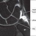
The radius makes up three-fourths of the joint socket of the wrist, consisting of the fossa scaphoidea and the fossa lunata of the radius, and one-fourth is formed by the triangular fibrocartilage complex (TFCC). The sigmoid notch of the radius adjoins the ulnar side of the socket and cradles the ulnar head in the distal radioulnar joint ( Fig. 12.1 ). The radiocarpal joint surface of the radius is tilted toward the ulnar and palmar aspects. A tendency of the carpus to drift because of this slope is prevented by a group of ligaments that pull in the opposite direction—the so-called “extra-articular slingshot ligaments” (RSLL, RLTL, RSCL, and DRTL), which extends from proximalradial to distal-ulnar, and the so-called “palmar support ligaments” (RSCL, RLTL, ULL, UTL). These ligaments are discussed in detail in Chapter 10.

Joint Angle of the Distal Radius Segment
The frontal angle of the radius (ulnar inclination of the radius) is measured in dorsopalmar radiographs with the wrist in neutral position (Fig. 12.2a). This refers to the angle between two connecting lines:
A tangent drawn between the tip of the radial styloid process and a point in the middle between the palmar and dorsal corners of the sigmoid notch of the radius,
A line drawn perpendicular to the longitudinal axis of the radius (DiBenedetto’s method) or the longitudinal axis of the ulna (Matsushita’s method).
The mean value of the frontal angle of the radius is 23° (normal range: 15–35°).
In case of malunion of distal radius fractures, determination of both the dorsal and palmar values of the frontal angle is useful as it enables already the sagittal malalignment of the radius in dorsopalmar radiographs. If there is a pathological dorsal tilt, the ulnodorsal corner of the radius is proximal to the ulnopalmar edge.
The sagittal angle of the radius (radius tilt, palmar inclination) is determined in the lateral radiograph of the wrist in neutral position (Fig. 12.2b), where the distal radius should be visualized for a length of at least 6cm. This is defined as the angle between the line drawn perpendicular to the longitudinal axis of the radius and a tangent between the corners of the dorsal and palmar rims of the radius in the lateral radiograph. The mean palmar inclination of the radius is 11° (normal range 0–20°).

Relative Lengths of the Radius and the Ulna
The length ratio between the radius and the ulna, known as the ulnar variance, may only be determined in dorsopalmar radiographs of the wrist in neutral position because of the translational movement during pronosupination of the forearm. Of the different methods of determining the ratio, Gelberman’s is the most commonly used ( Fig. 12.3 ). A 2 mm difference in length between the radius and the ulna is considered normal.
The height of the radial styloid process is determined in dorsopalmar radiographs. The value is defined as the distance between the tip of the radial styloid process and a line drawn perpendicular to the longitudinal axis of the radius which touches the sigmoid notch distally (Fig. 12.2a). It is useful to determine this value in chauffeurs’ fractures (Chapter 17). The normal value is between 11 and 13 mm (normal range 8–17 mm).
Radioulnar Translation
The relative length of the ulna changes during pronosupination of the forearm. The ulna assumes a distal position in relation to the radius during pronation and a proximal position during supination. Nonstandardized imaging procedures can therefore mimic a long ulna (positive ulnar variance) or a short ulna (negative ulnar variance).


Rotation of the Forearm (Pronosupination)
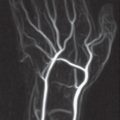
Rotation of the forearm and the hand is carried out in constant-phase congruence at the proximal and distal radioulnar joints. The mean range of rotational motion in pronation is 85° and in supination is 90°. The starting point is the neutral position, i.e., the upper arm adducted, the elbow flexed 90°, and the palm facing medially (Chapter 1). Rotation in the distal radioulnar joint takes place around the ulna as a fixed point around which the radius rotates together with the hand. The radius sweeps over the surface of a conic segment. The greatest possible congruence of the joint surfaces exists in neutral position( Fig. 12.4 ). During pronation and supination the joint surfaces of the ulnar head and the sigmoid notch of the radius have less contact (see Fig. 1.2 ).
Morphometry and Function of the Carpus
Radiographic Carpal Arches
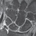
The bones of both carpal rows are arranged so that they form three harmonious parallel arches in dorsopalmar radiographs ( Fig. 12.5 ):
The first carpal arch connects the proximal contours of the proximal carpal row.
The second carpal arch connects the distal contours of the proximal carpal row.
The third carpal arch connects the proximal contours of the distal carpal row.
Every interruption or step in an arch must arise suspicion of an articular derangement contributing to carpal instability. Arches that are not parallel are suspicious for an unstable carpus. A triangle-like lunate, which is normally trapezoidal in shape in dorsopalmar radiographs, should be also considered pathologic.
Carpal Angles
Measuring four angles in lateral radiographs (in neutral position!) facilitates the recognition of discrete carpal malalignment. Longitudinal axes are drawn through the radius, the lunate, the scaphoid, and the capitate to determine the radiolunate, radioscaphoid, scapholunate, and capitolunate angles ( Figs. 12.6 , 12.7 ). Either the axial method (connecting lines between the middle of the proximal and distal joint surfaces) or the tangential method (a tangent along the palmar aspect of the scaphoid and the dorsal side of the capitate and a line perpendicular to the line connecting the anterior and posterior horns of the lunate) is used for this purpose. Normal values and ranges are listed in Table 12.1 .
When the carpus is intact, the longitudinal axes through the radius, the lunate, and the capitate, as well as through metacarpal III, can be lengthened in a straight line, i.e., these axes are arranged colinear (see Fig. 12.9a). Because of the physiological variations and inaccuracies in measurement (especially of the lunate), a colinear connecting line is found in only about 10% of healthy hands. Results within the normal ranges are, therefore, considered normal. Images depicting abnormal results can be found in Chapter 23.
Angle | Mean Value | Normal Range |
Radiolunate | 0° | −15°to + 15° |
Radioscaphoid | 0° | 30°to 60° |
Scapholunate | 47° | 30°to 60° |
Capitolunate | 0° | −15°to +15° |
Carpal Height
The proximal carpal row can be reduced in height in the presence of carpal instabilities, lunate osteonecrosis, and unstable scaphoid nonunion. The longitudinal extension of the carpus is assessed by comparing the length of the carpus with that of the adjacent metacarpus. Two indices are available ( Fig. 12.8 ):
Youm’s index of carpal height: The ratio of the length of the carpus (measured by continuing the longitudinal axis along the axis of metacarpal III) and the length of metacarpal III. The normal value is 0.54 ± 0.03.
Nattrass’ modified index of carpal height: If the metacarpus is not entirely on the radiograph, the ratio the length of the carpus (measured by continuing the longitudinal axis of the capitate) and the length of the capitate is calculated. The normal value is 1.57 ± 0.05.


Related posts:

Stay updated, free articles. Join our Telegram channel

Full access? Get Clinical Tree


