Evaluating the Intestinal Air or Gas Pattern
Gastrointestinal Contrast Studies
Antegrade Small Bowel Examination
Retrograde Small Bowel Examination
Study of Gallbladder and Biliary Tract
Excretory Urography and Computed Tomography Urography
Other Urinary Tract Examinations
Computed Tomography and Magnetic Resonance Imaging of the Abdomen
How to Read Abdominal Computed Tomography and Magnetic Resonance Imaging
Imaging Features of Gastrointestinal Abnormalities Using Traditional Contrast Radiographs
Imaging Features of Genitourinary Abnormalities
Obstetric and Gynecological Imaging
Accessory Digestive Organs—Imaging
Special Problems in Abdominal Imaging
Careful history and physical examination allow diagnosis of most abdominal complaints. When diagnosis remains uncertain following these procedures, an abdominal radiograph is often the first diagnostic imaging procedure requested. Recall that in women of childbearing age, consideration of possible pregnancy should precede a radiograph.
The anteroposterior (AP) radiograph (often referred from “KUB,” i.e., kidney, ureter, bladder), the most frequently performed abdominal imaging study, is performed with the patient supine (Fig. 3.1A). An upright radiograph (Fig. 3.1B) is useful in searching for free intraperitoneal air and/or intestinal air–fluid levels. If the patient cannot stand, a decubitus radiograph obtained with the patient lying on either the right or, preferably, the left side (Fig. 3.1C) can be substituted.
Step 1 is to position the radiograph correctly on the viewbox, with the film R (right side) marker opposite the viewer’s left side and the patient’s head toward the top of the film. On the AP upright radiograph, there should be a sign indicating an upright view, usually an arrow near the R or L marker, pointing toward the patient’s head. Similarly, decubitus radiographs should be clearly labeled as such and should note which side is up or down.
Step 2 is to glance at the entire radiograph in a relaxed manner to allow an obvious abnormality to jump out at you. When you do discover an abnormality, do not terminate your subsequent search.
Step 3 is to evaluate the radiograph systematically. Any system or checklist will suffice. Table 3.1 will work, until you develop your own. First, locate the water density liver and spleen silhouettes. One clue to locating liver and spleen edges is the presence of bowel gas in the right and left upper abdominal quadrants. Such bowel gas permits an indirect estimate of the location of the hepatic and splenic borders, because the gas is located at the lower edges of the liver and spleen. With a little experience, you will recognize a normal-sized liver. When the liver shadow extends to the iliac crest, it is usually enlarged. Also with more experience, you will readily detect an enlarged spleen (splenomegaly; Fig. 3.2).
In the normal radiograph, psoas muscle margins are usually visible. A nonvisible psoas margin should alert you to a possible abnormality adjacent to that structure. As your eyes drift toward the renal shadows, evaluate their size, shape, and position. The renal silhouettes are visible because they are water density structures (gray) surrounded by variable amounts of retroperitoneal fat (black). You should attempt to locate the upper and lower renal poles as well as their medial and lateral borders. If the renal long axis is not parallel with the psoas muscle margin, you should consider a mass or other water density abnormality in the kidney or the retroperitoneum. Always look for calcifications (white) in the abdomen, especially in the region of the kidneys, ureters, urinary bladder, and the gallbladder (discussed later).
The term Aunt Minnie, coined by the late Dr. Ben Felson, refers to the unmistakable and unforgettable appearance of your Aunt Minnie, or Uncle Al, or any other family character. A radiologic Aunt Minnie describes an image appearance so classic that, once you see it, you never forget it. The following abdominal radiographic Aunt Minnies (Figs. 3.3 to 3.9) are commonly encountered. File them away in your visual–cerebral computer, and your ability to recognize them will make you a star in the eyes of your colleagues, teachers, and patients.

FIGURE 3.1 A: Patient positioning for an AP supine abdomen radiograph. This examination is performed with the patient supine, either on a radiographic table or in bed (using a portable x-ray unit). B: Patient positioning for an AP upright abdomen radiograph. This examination is usually accomplished in the radiology department, with the patient standing. C: Patient positioning for a left lateral decubitus abdomen radiograph. The patient’s arms are positioned comfortably out of the way.
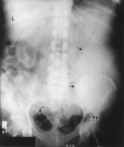
FIGURE 3.2 Abdomen AP supine radiograph. Splenomegaly. The water density spleen is enlarged (straight arrows), and the inferior margin projects just above the left hip (double straight arrows). The large spleen has displaced the intestinal gas into the right abdomen. The liver size is normal (L, liver). Incidentally noted are phleboliths (curved arrows), small intravenous stones secondary to calcified thrombi.
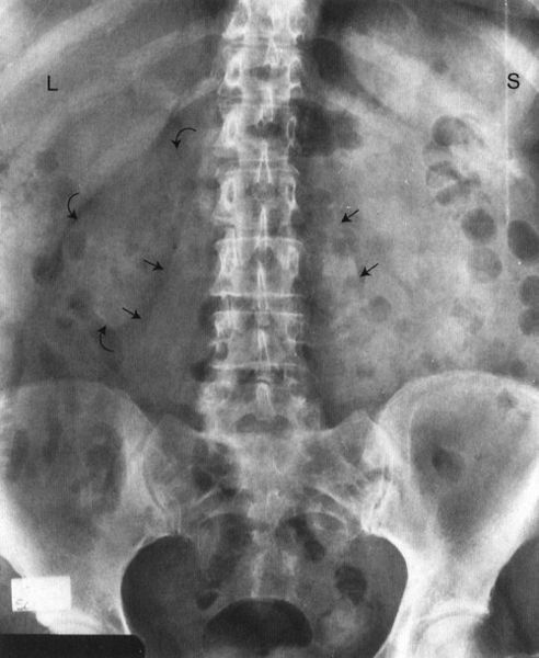
FIGURE 3.3 Abdomen AP supine radiograph. Normal. The psoas muscles (straight arrows) and the right kidney (curved arrows) are visible. The left renal silhouette is obliterated by intestinal gas. It is common to have intestinal gas and contents obliterating the renal shadows. (L, liver; S, spleen).
Now, evaluate the bowel gas pattern (see the next section). Last but not least, look at the bones systematically, beginning with the visible ribs and spine (Fig. 3.10). Study the pedicles of the lower dorsal and lumbar spine, proceeding from head to foot. They resemble automobile headlights on an AP radiograph. A missing pedicle indicates a destructive process, such as metastatic disease. Evaluate all visible bones, including the pelvis, hips, and femurs, for their overall density and any abnormalities.

ROUTINE FOR EVALUATING ABDOMINAL RADIOGRAPHS
- Once-over glance
- Liver and spleen
- Psoas shadows
- Renal contours and position
- Abdominal calcifications
- Intestinal gas pattern
- Bones
Use a similar search system for the AP upright abdominal radiograph while being especially alert for free air beneath the diaphragms. Free intraperitoneal air is usually visualized only on an upright radiograph, because only this position allows free air to rise to the subdiaphragmatic regions.
EVALUATING THE INTESTINAL AIR OR GAS PATTERN
Intestinal gas (black) provides a natural contrast medium that can be useful for detecting abdominal disease. When evaluating the intestinal gas pattern, ask yourself several important questions. Is the bowel gas pattern normal? Remember that there is normally some air or gas in the stomach, small intestine, colon, and rectum. With experience, you will begin to recognize abnormal amounts of air in the gastrointestinal (GI) tract. This is similar to recognizing a normal heart on a chest radiograph. If the gas pattern is not normal, ask more questions. Is there too much or too little air? Is the air in the wrong place?
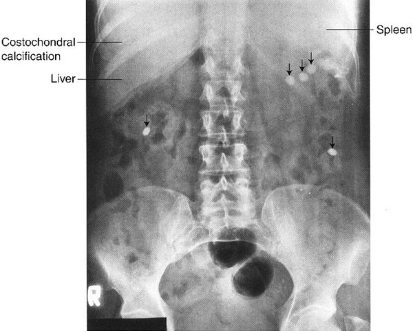
FIGURE 3.4 Abdomen AP supine radiograph. Classic appearance of tablets or pills (straight arrows) in the GI tract. All the tablets are the same size and shape with homogeneous density. (Not all tablets or pills can be visualized on a radiograph.)
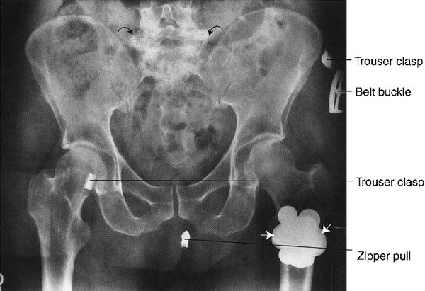
FIGURE 3.5 Abdomen AP supine radiograph. Metal coins (straight arrows) in the left trouser pocket. The patient was not completely disrobed prior to obtaining the radiographs. Note the degenerative or osteoarthritic changes in the lower lumbar spine (curved arrows).
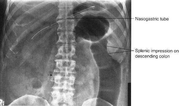
FIGURE 3.6 Abdomen AP supine radiograph. An umbrella-shaped inferior vena cava filter (straight arrow), placed in the inferior vena cava by angiographic technique, entraps venous thromboemboli originating in the lower extremities and pelvis.
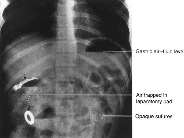
FIGURE 3.7 Abdomen AP upright radiograph. Surgical laparotomy pad in a postoperative abdomen. The radiograph was obtained when the patient experienced severe postoperative abdominal pain and distention. The straight arrow indicates the opaque strip in the laparotomy pad, and the curved arrow indicates the metallic ring attached to the laparotomy pad. Note the mottled black appearance of the air trapped in the laparotomy pad. The air–fluid level in the gastric fundus gives a clue to the upright position of the patient.
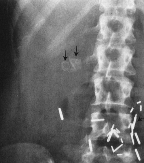
FIGURE 3.8 Abdomen AP supine radiograph. Cholelithiasis (gallstones). The calcified calculi (straight arrows) are faceted. Surgical metallic clips (curved arrows) are secondary to previous abdominal surgery.
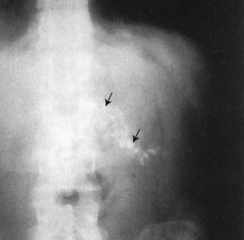
FIGURE 3.9 Abdomen AP supine radiograph. Calcifications (straight arrows) in the body and tail of the pancreas owing to chronic pancreatitis.
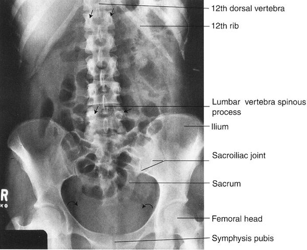
FIGURE 3.10 Abdomen AP supine radiograph. Normal. Representative vertebral pedicles are shown by straight arrows. The water density urinary bladder is shown by curved arrows.
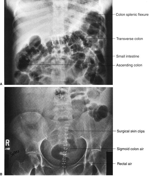
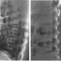
FIGURE 3.11 A: Abdomen AP supine radiograph. Postoperative adynamic ileus. Air is present throughout the entire GI tract, including the rectum (not shown). Note the haustrations in the transverse colon. B: Lower abdomen AP supine radiograph 24 hours later in the same patient. A considerable amount of intestinal air has moved into the rectum and sigmoid colon, confirming the diagnosis of adynamic ileus.
Here, where differential diagnosis includes adynamic ileus and bowel obstruction, we need a systematic approach to arrive at the correct diagnosis. In adynamic ileus (also referred to as paralytic ileus or just ileus), there is too much bowel gas in the entire GI tract, including the small and large intestines (Fig. 3.11A, B). Adynamic ileus may arise from intra-abdominal cases or as a reflex phenomenon from disease elsewhere. The multiple etiologies are listed in Table 3.2. If you identify comparable amounts of gas in the small and large intestines and in the rectum, this generally indicates adynamic ileus. Air in the rectum may be a key differential point.

ADYNAMIC ILEUS—MAJOR CAUSES
Intra-abdominal
■ Postoperative or posttraumatic
■ Postinflammatory: pancreatitis, enteritis, colitis
■ Pain-related: renal colic, epidural disease
Extra-abdominal
■ Septicemia
■ Metabolic disease: hyperkalemia, uremia
■ Medications (especially narcotics)
■ Prolonged bed rest
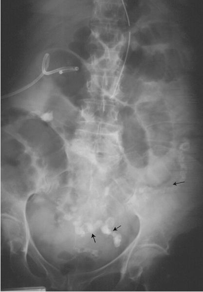
FIGURE 3.12 Abdominal radiograph. Small bowel obstruction. There are many dilated loops of small bowel in the midabdomen. They are identified as small bowel by their position, semihorizontal orientation, and valvulae conniventes traversing the entire transverse diameter. There is a small amount of residual barium in a collapsed descending colon (arrows). Incidentally noted are the nasogastric and abdominal drainage tubes. (Courtesy of Bruce Brown, M.D.)
In intestinal obstruction, another reason for too much bowel gas, there is usually air-filled, dilated intestine proximal to the point of obstruction and little or no air distal to the obstruction (Fig. 3.12). In both ileus and obstruction, often the dilated small and large bowels containing too much air will have air–fluid levels noted on upright and decubitus radiographs.
If a diagnosis of obstruction versus adynamic ileus is not readily apparent, it is necessary to obtain additional studies to arrive at the correct diagnosis. These include barium studies, computed tomography (CT) (Fig. 3.13), and ultrasound (US). Note the relative ease of identifying small versus large bowel using CT.
If you diagnose intestinal obstruction, you next need to determine the location of the obstruction. Is the obstruction in the small or large bowel? In small bowel obstruction, there are loops of dilated small bowel proximal to the obstruction site and little or no gas in the colon or the rectum. In large bowel obstruction, there is dilated colon proximal to the obstruction site but little or no air distally and minimal air in the rectum.
Sometimes it is difficult to differentiate dilated small from large bowel. One way is to identify the valvulae conniventes and colon haustra. Valvulae conniventes are regularly spaced, thin mucosal folds that extend across the entire small bowel lumen (Fig. 3.12). On the other hand, the colon can usually be identified by the somewhat irregularly spaced transverse bands, called colon septa or haustral folds, that do not extend completely across the colon lumen (Fig. 3.11).
Sigmoid volvulus is a dramatic clinical event that occurs predominantly in elderly patients with a long history of constipation. The chronic constipation results in a redundant sigmoid mesentery that has the potential to twist on itself like a garden hose. If twisting occurs, there is complete or partial obstruction, and an abdominal radiograph shows a dramatically dilated sigmoid colon. Barium enema is confirmatory, with complete obstruction to the retrograde flow of barium at the site of the twist (Fig. 3.14). The obstruction can often be relieved by gently passing a sigmoidoscope past the point of the obstruction or twist.
When the abdominal radiographs show a paucity or absence of bowel gas, the differential diagnosis listed in Table 3.3 should be entertained.
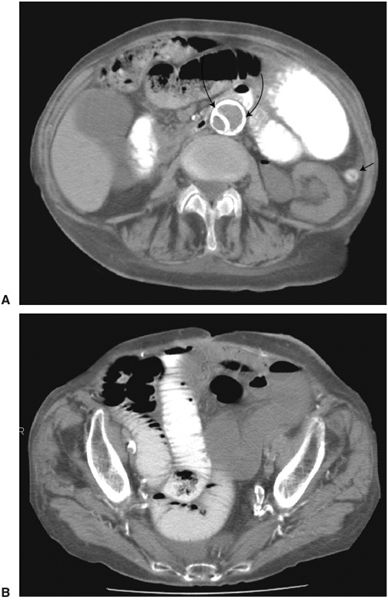
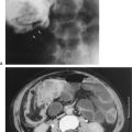
FIGURE 3.13 Abdominal axial CT. Small bowel obstruction. A: Here are many dilated loops of small bowel, some of which contain barium. The only colon visualized (arrow) in the left lower abdomen is tiny. (The aortic image (curved arrows) shows a segment of calcified intima, indicating previous aortic dissection.) B: CT at the level of the pelvis confirms the dilated small bowel extending into the pelvis (the rectum is surgically absent). (Courtesy of Gerald Decker, M.D.)
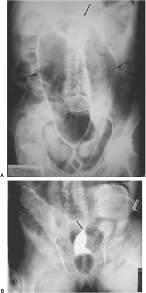
FIGURE 3.14 Sigmoid volvulus A: Abdominal radiograph. The air-filled, obstructed sigmoid colon (arrows) arises from the pelvis. B: Barium enema. Contrast introduced per rectum shows obstruction and a twist (arrow) at the sigmoid colon. (Courtesy of Bruce Brown, M.D.)

TOO LITTLE BOWEL GAS
■ Enlarged abdominal organs
■ Intra-abdominal tumor
■ Fluid-filled intestines
■ Gastroenteritis
■ Neurological deficit (with reduced swallowing)

ABDOMINAL AIR OR GAS IN THE WRONG PLACE
■ Pneumoperitoneum from ruptured intestines: ulcer, trauma, cancer, enteritis
■ Abscess
■ Pneumatosis intestinalis
There are several situations in which air is found outside of the intestinal lumen (Table 3.4). Free air in the peritoneal cavity results from any process that perforates the intestinal tract. AP supine and upright abdominal radiographs should be performed if there is clinical suspicion of gut perforation. The upright position allows free intraperitoneal air to rise to the subdiaphragmatic regions of the abdomen (Fig. 3.15). If the upright view is not possible owing to the patient’s condition, a decubitus radiograph will suffice. On a decubitus radiograph, the air rises to the nondependent portion of the peritoneal cavity (Fig. 3.16). Either technique has the potential to identify as little as 2 cc of free intraperitoneal air, as long as the patient is in the upright or decubitus position approximately 5 minutes prior to the radiograph.
Another example of air in the wrong place is pneumatosis intestinalis (Fig. 3.17). Causes of this are listed in Table 3.5. Gas-filled abscesses can be found in any location, including the abdomen (Fig. 3.18).
GASTROINTESTINAL CONTRAST STUDIES
For inspection of the mucosal surface of the esophagus, stomach, and duodenum, endoscopy is often preferred. To evaluate the gut lumen and wall, traditional radiologic GI contrast studies are accurate, safe, and less expensive than the endoscopic studies and enjoy excellent patient acceptance. These studies consist of fluoroscopy and radiographs obtained following introduction of barium sulfate (metallic density or white) and/or air (black) into the GI tract.
For an upper GI series, the patient swallows liquid barium, often combined with gas-producing crystals, under fluoroscopy to visualize the esophagus, stomach, and small intestine (Fig. 3.19). When both barium and air are used, the process is referred to as a double-contrast study. When barium is used alone, it is a single-contrast study. Preparation for an upper GI series consists simply of nothing by mouth (non per os [NPO]) for 8 to 12 hours prior to the study. When perforation of the upper GI tract is suspected, water-soluble contrast media is used.

PNEUMATOSIS INTESTINALIS
■ Bowel ischemia
■ Steroid and immunosuppressive therapy
■ Proximal to intestinal obstruction
■ Collagen diseases
■ Neonatal necrotizing enterocolitis
■ Benign idiopathic pneumatosis
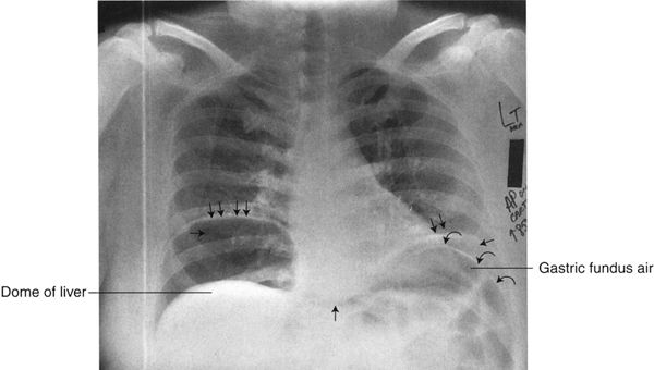
FIGURE 3.15 Chest AP upright radiograph. Free intraperitoneal air. The right and left hemidiaphragms (double arrows) are elevated owing to bilateral subdiaphragmatic air (single straight arrows). The black zone between the right hemidiaphragm and the dome of the liver represents free intraperitoneal air. On the left, there is air in the gastric fundus as well as free air surrounding the gastric fundus, allowing visualization of both sides of the stomach wall (curved arrows). When you see both sides of the gut wall, this represents free intraperitoneal air (Rigler’s sign).
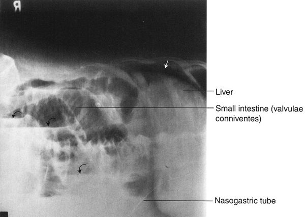
FIGURE 3.16 Abdomen left lateral decubitus radiograph (left side down). Free intraperitoneal air in a patient with small bowel obstruction and perforation. The free intraperitoneal air (straight arrow) is between the right rib cage and the liver. The dilated small bowel contains multiple air–fluid levels (curved arrows).
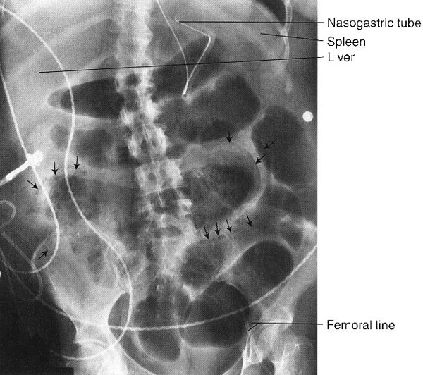
FIGURE 3.17 Abdomen AP supine radiograph. Pneumatosis intestinalis (air in the bowel wall). There is widespread bubbly air within the small intestine walls (arrows).
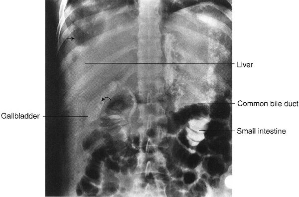
FIGURE 3.18 Abdomen AP supine radiograph. Right subdiaphragmatic abscess. The black areas along the right lateral aspect of the liver represent air in the abscess cavity (straight arrows). Incidentally noted is contrast material in the common bile duct, gallbladder, and small bowel, injected during an endoscopic retrograde cholangiopancreatography (ERCP). Some of the contrast spilled into the small intestine. The filling defect (curved arrow) in the gallbladder is probably a calculus.
FIGURE 3.19 Normal upper GI series. Barium filled stomach and duodenum. The patient is in the prone position. Gas (short arrow) is seen in the gastric fundus, a peristaltic wave (long arrows) crosses the gastric antrum, the pylorus (curved arrows) separates the duodenal bulb and stomach.
Antegrade Small Bowel Examination
The usual small bowel examination is performed after an upper GI series by having the patient drink additional barium. Serial radiographs of the abdomen are performed at 15- to 30-minute intervals thereafter to evaluate the small bowel as barium passes through (Fig. 3.20). Fluoroscopy is commonly used as a supplement to study the terminal ileum when barium begins to enter the colon or to further investigate abnormalities seen on the serial radiographs.
Enteroclysis is a focused examination of the small intestine, wherein air and barium sulfate are introduced directly into the small intestine via a nasointestinal tube. Under fluoroscopy, the tip of the tube is placed just beyond the duodenal–jejunal junction and contrast is injected (Fig. 3.21). Advantages of this procedure are that the small bowel can be distended and the stomach and duodenum do not obstruct visualization. The main disadvantages are the discomfort associated with a nasal tube and the radiation exposure.
FIGURE 3.20 Normal antegrade small bowel examination. Barium was administered by mouth, and this radiograph was done about 30 minutes later. Note the barium-filled stomach, duodenal C-loop, feathered jejunum in the upper abdomen, and relatively formless mucosa of the ileum in the lower and right abdomen. The terminal ileum (arrows) entering the cecum can be identified. (Courtesy of Bruce Brown, M.D.)
Retrograde Small Bowel Examination
On occasion, especially when disease of the terminal ileum is suspected and previous examinations are nondiagnostic, barium can be refluxed from a filled colon into the ileum. Although the procedure is useful, there is considerable patient discomfort, alleviated slightly by antispasmodic agents.
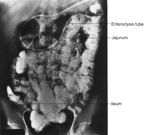
FIGURE 3.21 Small bowel enteroclysis. Normal. The nasointestinal tube has been positioned just beyond the duodenal–jejunal junction. Barium fills the entire small bowel.
Introduction of barium sulfate and/or air into the colon via a rectal tube is called a lower GI series or barium enema. For this study, it is important to have a clean colon; this is best accomplished with laxatives and large amounts of orally ingested fluids. Barium and often air are administered via a rectal tube under fluoroscopic observation. When both air and barium are used, it is called a double-contrast study (Fig. 3.22), whereas barium alone is a single-contrast study. A properly performed barium enema has minimal associated discomfort. The double-contrast study is preferred to evaluate intraluminal and mucosal diseases, such as small ulcers and polyps. Again, if colon perforation is suspected, a water-soluble contrast medium is used.
Colonoscopy, an expensive alternative to colon barium studies, can directly visualize the mucosa. However, it requires conscious sedation because of patient discomfort. Virtual colonoscopy is an examination of the entire colon using multidetector CT and a dedicated software program so that the colon is displayed throughout its length with stacked images created to form a three-dimensional (3-D) picture of the colon at each level. The examination is usually performed after administration of an agent that tags fecal material, which can then be subtracted from the viewed images. Before the examination begins, the colon is insufflated with air so that the images resemble the interior view of the colon as would be seen by endoscopy. Virtual colonoscopy has the ability to discover almost all colon cancer (Fig. 3.23) as well as larger polyps (Fig. 3.24) (which are premalignant). The examination takes but a few minutes and does not require the sedation and analgesics required for optical colon endoscopy. As experience with the technique has increased, it seems more accurate than barium enema techniques and perhaps as good as optical colonoscopy. Its disadvantages are the use of radiation and probably reduced detectability of flat mucosal lesions. It is much less expensive than optical colonoscopy. At the time of this writing, indication for its use as a substitute for screening optical colonoscopy is imprecise, but considerable improvement of the technique is anticipated.
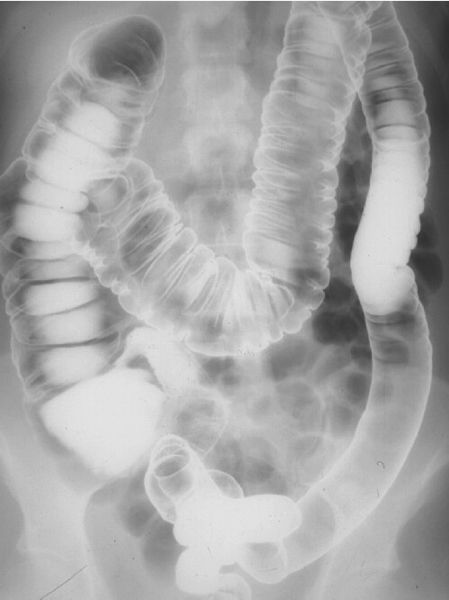
FIGURE 3.22 Barium–air contrast colon examination. The entire colon is filled with barium and air. Films are made in prone, supine, and both decubitus positions so that different parts of the colon can be visualized with the air-contrast techniques. (Courtesy of Bruce Brown, M.D.)
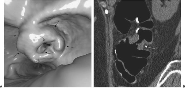
FIGURE 3.23 “Apple core” invasive cancer discovered on virtual colonoscopy. A: The virtual colonoscopy image shows a large endoluminal mass (straight arrows), associated with narrowing of the colon lumen (curved arrows). B: Coronal CT reconstruction of the colonoscopic image. The tumor (arrows) is noted on both sides of the colon lumen and extrudes into the pericolic space. (Courtesy of J.G. Fletcher, M.D.)
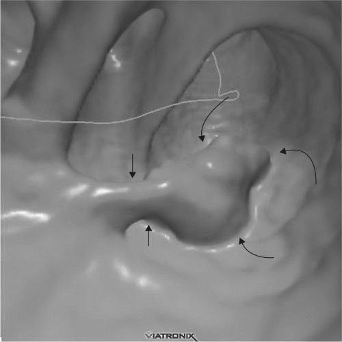
FIGURE 3.24 Virtual colonoscopy. Colon polyp detected in virtual colonoscopy. The stalk (short arrows) and the polyp (curved arrows) are readily apparent. (Courtesy of Wei Chang, M.D.)
STUDY OF GALLBLADDER AND BILIARY TRACT
In years past, the oral cholecystogram was performed to visualize the gallbladder following the oral ingestion of special iodinated compounds that are excreted into the biliary system and subsequently concentrated in the gallbladder. The study is seldom performed now because of the greater accuracy of US. With US, one can examine the liver and biliary tract as well as the gallbladder. CT and magnetic resonance imaging (MRI) are needed in certain situations to complement US.
In endoscopic retrograde cholangiopancreatography (ERCP), the endoscopist passes a fiberoptic scope under fluoroscopic control antegrade through the esophagus, stomach, and duodenum and retrograde into the common bile duct. The pancreatic ducts can also be cannulated. Contrast media can be injected into any of these structures and appropriate radiographs obtained (Fig. 3.25). ERCP is usually performed when less-invasive studies (CT, US, MRI, or contrast studies) are indeterminate or nondiagnostic or as part of a therapeutic endoscopic procedure.
The first methodology to examine the urinary tract directly (about 1900–present) was to inject radiopaque material directly into the bladder or other urinary structures (retrograde cystography or pyelography) at the time of cystoscopy. It was later discovered that intravenous contrast material that is excreted by the kidneys could be given with relative safety; excretory urography (EU) was developed shortly thereafter. Other names given for the EU are intravenous urogram and intravenous pyelogram. Multislice CT has now evolved as the new standard, CT urography (CTU). A multifaceted radiologic approach to genitourinary (GU) problems is now possible, with supplemental US and MRI examination.
EU with traditional radiographs, although still a useful technique, is performed much less frequently in the investigation of GU disease than is CTU, principally because the renal parenchyma, pelvicalyceal system, ureter, and bladder can be more accurately visualized with multislice techniques. US remains a valuable technique to complement radiographic investigation.
Excretory Urography and Computed Tomography Urography
Both EU and CTU involve the administration of an intravenous contrast medium that is excreted by the kidneys. In CTU the contrast medium is delivered in bolus fashion to maximize renal parenchymal visualization. In EU one recognizes the urinary structures as seen through overlying bowel gas, soft tissue, and so on. In CTU, multidetector CT is utilized, permitting visualization of urinary structures without overlying structures. A further advantage is the ability to reconstruct images in any plane—axial, coronal, and sagittal. A final advantage of CTU is a reconstruction technique so that the urinary tract is viewed in 3-D with all other structures subtracted.
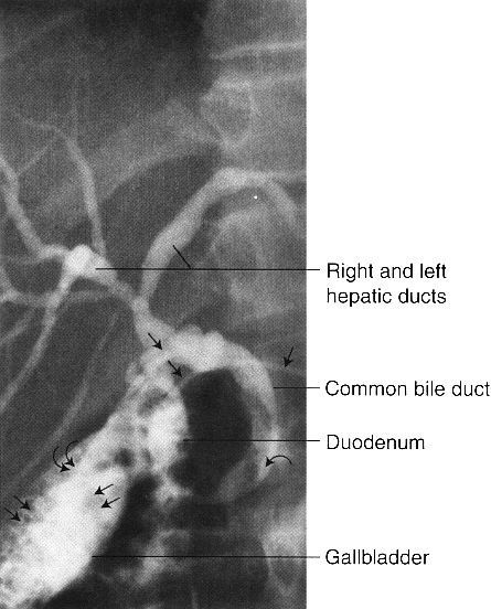
FIGURE 3.25 Endoscopic retrograde cholangiopancreatography (ERCP). Cholelithiasis and choledocholithiasis. The gallbladder is filled with calculi (double straight arrows), and there is a large calculus in the distal common bile duct (curved arrow). A nasobiliary drain (straight single arrows) is in place with the tip (double curved arrows) in the gallbladder.
Disadvantages of CTU include a higher patient radiation dose (about double) and additional cost. 3-D reconstruction requires image manipulation by a specially trained technologist. Thus, the EU remains an accepted technique for most children, for many follow-up studies, and at sites without multidetector CT. Both types of examinations are featured in this chapter.
Excretory urography (EU) and CT urography (CTU) do not require special patient preparation, merely abstaining from food and liquids for several hours before contrast administration.
The timing of EU and CTU radiographs can be varied, depending upon the patient’s clinical problems. Nevertheless, both techniques usually require examination during the nephrographic phase (for visualization of the renal cortex), followed by image(s) of the pelvicalyceal system and bladder, which are opacified later. Delayed films can be obtained for hours, or even days, in situations such as ureteral obstruction or renal failure.
Viewing an Excretory Urogram or Computed Tomography Urogram
An EU study begins with a preliminary or scout radiograph that includes the entire abdomen. You can evaluate this preliminary radiograph using the same system as described previously. The radiographs obtained immediately following intravenous contrast media demonstrate the nephrogram phase wherein the contrast media is located in the renal capillaries, glomeruli, and proximal convoluted tubules (Fig. 3.26A). Compare the nephrograms for symmetry, as size discrepancy is suspicious for unilateral renal disease.
Next, evaluate the later postcontrast injection radiographs, at which times the contrast media is normally present in the calyces, renal pelves, portions of the ureters, and urinary bladder (Fig. 3.26B). Normal calyces are sharp in outline, with various numbers and geometry. Oblique, prone, and abdominal compression radiographs are often obtained to better display portions of the urinary tract.
The CTU is evaluated for the same factors as the EU, albeit in different fashion. A computed abdominal radiograph is performed, followed by axial scans of the abdomen before, immediately after, and at a later time following the bolus of contrast material (Fig. 3.27). In special situations (e.g., study of renal donor), immediate postcontrast scans can be obtained to visualize renal arteries and later the veins. As in the EU, pay attention to size and symmetry of the kidneys, pelvicalyceal systems, and bladder.
Other Urinary Tract Examinations
Direct injection of contrast material into the bladder or ureter (retrograde pyelogram) is of value when a detailed view of a portion of the ureter or pelvicalyceal system is necessary. It is often an adjunct to endoscopy.
Vesicoureteral reflux, a condition in which bladder urine refluxes in retrograde fashion into the ureters, is a common phenomenon of children but infrequent in adults. It can be associated with urinary tract infection. With the voiding cystourethrogram, contrast medium is introduced via urethral catheter into the bladder. Subsequent fluoroscopy and filming allow one to identify and quantitate vesicoureteral reflux if present (Fig. 3.28). At the completion of the study, the patient voids, with the voiding sequence recorded in some imaging form. This allows detection of urethral abnormalities, which can produce bladder obstruction and secondary vesicoureteral reflux. Cystography and retrograde urethrography are examinations usually performed to detect urinary extravasation in trauma cases.
Ultrasound (US), being a different modality from x-rays, shows abdominal organs in a different fashion. There are roughly three patterns of reflected US:
- No reflection of the sound wave. Almost all of the sound passes through the area. This is termed sonolucent and is traditionally viewed as black on images. Fluid, such as in ascites or abdominal cysts, is sonolucent.
- Reflection of some and transmission of some sound. Solid organs, such as the kidney or liver, are examples. US waves are reflected, particularly at boundaries of organs of differing echogenicity, such as the boundary between the liver and kidney.
- Reflection of all sound. Bone, other calcifications, and air in the gut are examples. One can make use of this by noting such shadowing and the absence of echoes distal to a lesion to help diagnose gallstones and like abnormalities.
There are two major problems in learning to read US images:
- It requires one to think differently. You are looking at differences in transmission and reflection of US rather than transmitted x-rays.
- Orientation of the image. This is the chief stumbling block. One may consider the US image as representing a roughly pie-shaped wedge of tissues, less than 1 cm thick, below the US transducer.
Even experienced radiologists and clinicians have considerable difficulty figuring out the nature of the US image if they did not perform the study. Orientation must be provided by the person who performed the scan. In most situations, there is a relatively fixed method of performing abdominal US. In general, one evaluates each area of interest in at least two dimensions, typically axial (transverse) and longitudinal (sagittal). For technical reasons, the direction of the scan beam shows the anatomy best if it is perpendicular to the organ of interest. As few abdominal organs are 100% oriented anterior– posterior or medial–lateral, the scanned images are, to varying degrees, oblique.
Probably the best method to be introduced to US is to attend an imaging session with a knowledgeable mentor who discusses the anatomy as it is being scanned. Combined with this, learn the usual routines for US scanning in your institution and try to figure out how each image was performed. Conventionally, images are labeled as to the method by which they are done, for example, kidney—transverse.
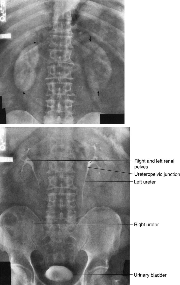
FIGURE 3.26 Abdomen AP EU. Normal. A: There are symmetric nephrograms 1 minute postinjection of contrast media. The renal outlines (straight arrows) are clearly defined owing to the presence of the contrast media within the kidneys. B: Note that it is possible to see the calyces, infundibula, renal pelves, portions of ureters, and urinary bladder on this 15-minute radiograph.
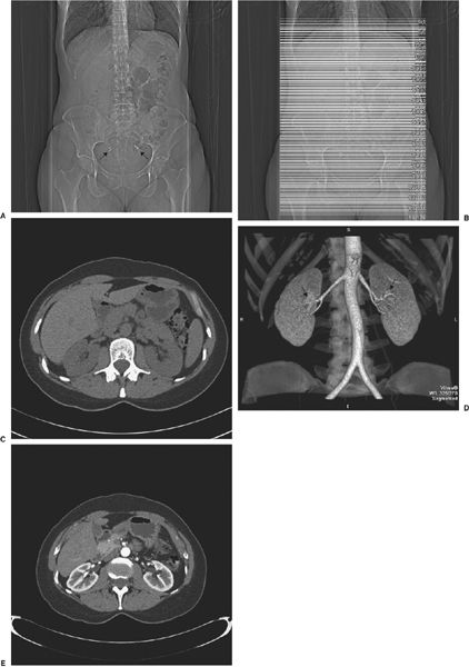
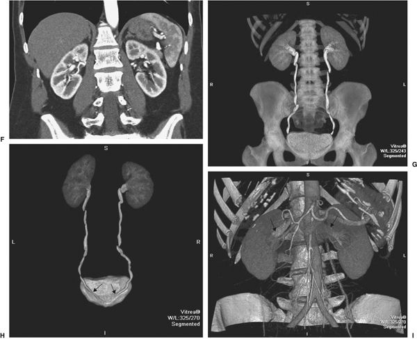
FIGURE 3.27 Normal CT urogram in a potential renal donor. A: Preliminary scout image of the abdomen is normal except for benign small calcifications (arrows) in the pelvis. B: Scout image with superimposed lines indicating the many axial slices performed to create the image data. C: One slice of the nonenhanced scan of the abdomen before administration of contrast. No abnormalities of the kidneys or other areas are noted. D: Coronal CT images after contrast administration shows aorta, single bilateral renal arteries (arrows), and normal size kidneys. E: Axial scan early after contrast demonstrates well demarcation of renal cortex and medulla. F: Coronal reconstruction at the same time as E. G: Later reconstructed coronal image showing normal kidneys, ureters, and bladder. H: Coronal image of the urinary tract viewed from posterior showing entry of the ureters into the bladder (arrows). I: Later coronal image showing both renal veins (arrows) as well as arterial structures.
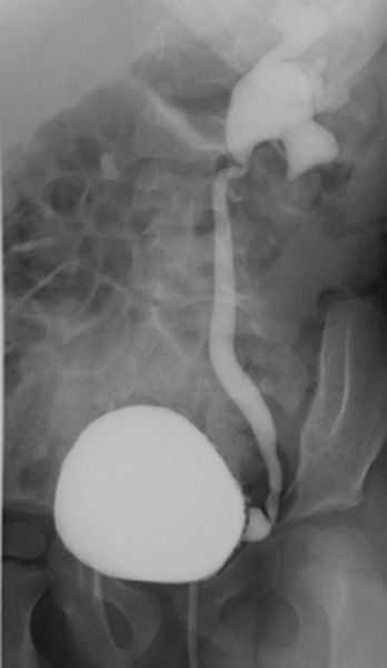
FIGURE 3.28 Cystourethrogram. Vesicoureteral reflux. Contrast introduced via urethral catheter into the bladder fills the bladder and refluxes into the left ureter.
There are many abdominal applications of US related to its widespread availability and cost (it is about half the cost of CT and about one third that of MRI). Ultrasonography is valuable in the workup of diseases involving the liver, biliary tract, kidneys, abdominal aorta, and abdominal masses. It is particularly useful in defining fluid versus solid (e.g., cyst versus solid mass) as well as in imaging fluid-filled structures, such as the gallbladder, urinary bladder, and renal pelvis. The various abdominal organs and pathologic processes have their own characteristic echo patterns, as shown in Fig 3.29.
Obstetric and gynecologic US is particularly important because of the absence of significant biological risk to the fetus or maternal genital structures. In obstetric US, the fetus is surrounded by amniotic fluid, making visualization easier (Fig. 3.30). In addition, one can use real-time US images to evaluate the beating heart. For gynecological examinations, both transabdominal (Fig. 3.31) and transvaginal techniques are used. Transvaginal imaging has the technical advantage of eliminating echoes from the abdominal wall from the area of interest, allowing better definition of genital organs (Fig. 3.32).
Diagnostic US of the prostate has been disappointing, as it is relatively insensitive to identifying abnormalities of this organ. In the scrotum, US is superb. It localizes the site of disease (e.g., testis versus epididymis) and often allows specific diagnosis of the abnormality present (Fig. 3.33). Correct diagnosis of epididymitis versus testicular torsion versus orchitis is possible, separating those who need surgery from those who require only medical treatment. Hydrocele and varicocele are easily identified with US. Identification of testicular tumors is good, although identifying tumor type is less reliable.
COMPUTED TOMOGRAPHY AND MAGNETIC RESONANCE IMAGING OF THE ABDOMEN
Both CT and MRI are useful in the diagnosis and management of abdominal disease. CT is usually the favored procedure because of its wide availability and lower cost. Patient motion is seldom a problem in CT but is a frequent occurrence in MRI. Both techniques have the ability to produce images in any dimension (axial, sagittal, coronal, or oblique).
Except in emergencies, the patient for CT has usually fasted for several hours. In most cases (suspected renal disease is the usual exception), a dilute contrast material (such as barium or iodine containing) is given orally before the study begins to demarcate the GI tract. This allows one to identify bowel loops, distinguishing them from masses and solid organs.
Immediately before (or sometimes during) abdominal CT, contrast material is injected intravenously to allow identification of arteries and veins (the enhanced CT). The intravenous contrast is excreted by the kidneys so that the kidneys (and later the urinary collecting systems and bladder) will be opacified (see CTU).
A relatively new examination is the positron emission tomography (PET)-CT (see nuclear medicine). A special machine combines CT and PET scanning so that the patient is not moved between examinations. Software programs fuse the CT and PET images into a single image. The advantage is to combine the PET-increased sensitivity of small tumors with the improved anatomical localization of CT.
The abdominal MRI examination is tailored to the suspected abnormality, the technical details being beyond the scope of this discussion. Intravenous contrast agents, such as gadolinium, which can change the MR signal in many organs and diseases, are frequently given as part of the MR study.
How to Read Abdominal Computed Tomography and Magnetic Resonance Imaging
Reading cross-sectional images of the abdomen is not particularly difficult for the neophyte radiologist if one’s anatomical knowledge is adequate. You will find the system for axial images described herein to be time-consuming but rewarding. First, arrange the images in order, from top (toward the head) to bottom. In many circumstances, that is already done for you electronically. Next, look at all the images (using the cine mode if available) in gestalt fashion to discover any obvious abnormalities. Then, look at each organ individually, from top to bottom (i.e., all CT slices containing the organ of interest). In each organ, evaluate the size and shape of each area of reduced or increased density. Do this for visible lung, liver, gallbladder, spleen, pancreas, adrenals, both kidneys and ureters, the bladder, and genitals. Evaluate the stomach, duodenum, small bowel, colon/appendix, and mesentery. Study the retroperitoneum from top to bottom—aorta, vena cava, and mesenteric vessels, also looking for adenopathy or other masses. Check the peritoneal cavity for fluid or masses. Look at the vertebrae (and spinal cord within) and bony pelvis. Finally, concentrate on the abdominal wall, hips, and adjacent soft tissues. Thoroughness leads to success in reading abdominal CT scans. The same methodology applies to evaluation of coronal and sagittal images.
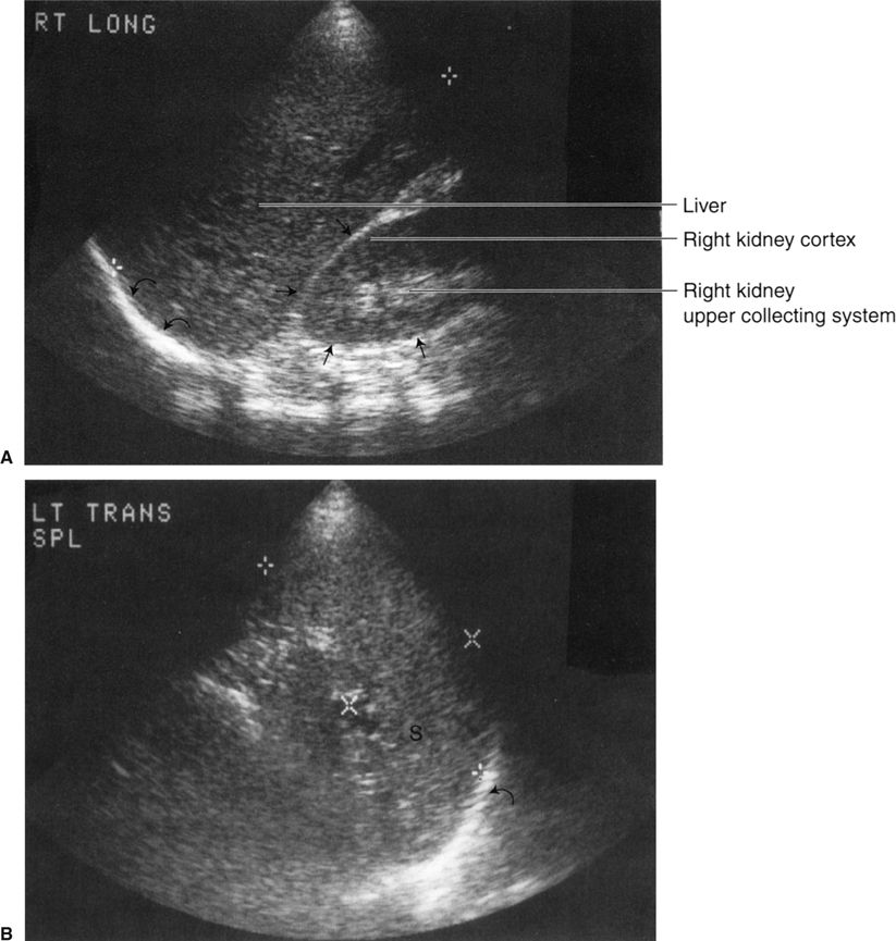
FIGURE 3.29 A: Longitudinal (sagittal) abdominal sonogram. Normal liver and right kidney echo patterns. The cross marks indicate the longitudinal (sagittal) liver dimension. The right kidney borders are demarcated by the straight arrows and the right hemidiaphragm by the curved arrows. B: Transverse (axial) abdominal sonogram. Normal spleen echo pattern. The side-to-side spleen dimension lies between the X marks, and the cephalocaudal dimension lies between the crosses. The left hemidiaphragm is indicated by the curved arrow (S, spleen). Note the labels on the images (A, Rt long; B, Lt trans spl). Such labels are helpful in orienting the images for the observer.
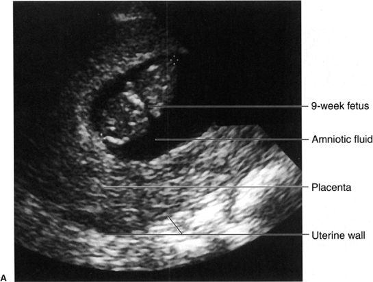
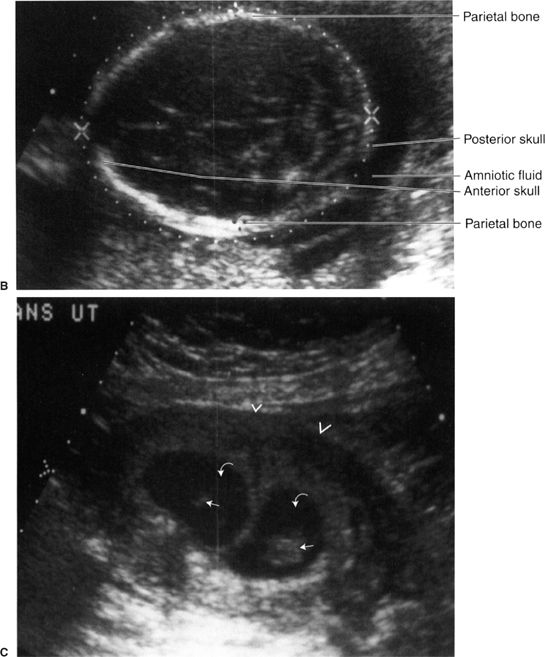
FIGURE 3.30 Obstetric sonograms A: Study in a 9-week fetus. The caliper markers indicating crown to rump distance confirm the 9-week gestation. B: Skull of a fetus near term. The white dotted lines outline the skull, and the biparietal diameter confirms the fetal age. The cerebral ventricles are vaguely seen within the skull. C: Twin pregnancy. The uterine wall is marked by the arrowheads. Each fetus (straight arrows) is surrounded by amniotic fluid (curved arrows). There are separate sacs.
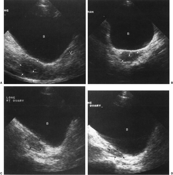
FIGURE 3.31 A: Transabdominal midline longitudinal (sagittal) sonogram. Normal uterus (straight arrows). The urine-filled bladder is essentially echo free and thus serves as an acoustic window to the pelvis. Notice the characteristic homogeneous echo pattern of the normal uterus. The endometrial stripe (curved arrow) represents the layers that line the endometrial cavity. The presence of the endometrial stripe indicates the absence of an intrauterine pregnancy or other intrauterine mass (B, urinary bladder; V, vagina). B: Transabdominal transverse (axial) sonogram. Normal uterus. The uterine fundus is outlined by the straight arrows; the endometrial stripe (curved arrow) appears smaller on the transverse image. C: Transabdominal right longitudinal (sagittal) sonogram. Normal right ovary (straight arrows). D: Transabdominal left longitudinal (sagittal) sonogram. Normal left ovary (straight arrows).
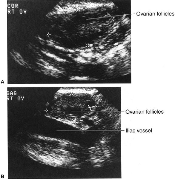
FIGURE 3.32 Transvaginal sonograms of the right (A) and left (B) ovaries. The dimensions of the ovaries are indicated by the X marks and crosses. Note the better definition of the ovaries, so that follicles are visible, when compared with the transabdominal images (Fig. 3-31).
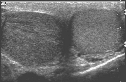
FIGURE 3.33 Transverse scrotal sonogram. The left testis is normal. The right testis is enlarged, has reduced echogenicity, and shows streaky, black linear echodensities. These findings indicate orchitis. (Courtesy of Monzer Abu-Yousef, M.D.)
The same system can also be applied to abdominal MRI, but—unfortunately for the nonradiologist—there are usually many more images, often with oblique planes and several pulse sequences, often later supplemented with intravenous magnetic contrast material. Normal abdominal CT and MRI anatomy is illustrated in Figs. 3.34 to 3.45.

FIGURE 3.34 A: Illustration of the approximate axial anatomic level through the liver and spleen for B and C. B: Abdomen axial CT image through the liver and spleen. Normal. C: Abdomen axial MR image through the liver and spleen. Normal.
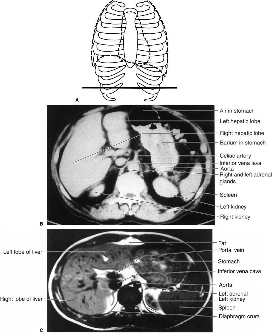
FIGURE 3.35 A: Illustration of the approximate axial anatomic level through the liver and spleen for B and C. This level is just caudad to the level in Fig. 3.34. B: Abdomen axial CT image through the liver and spleen. Normal. C: Abdomen axial MR image through the liver and spleen. Normal.
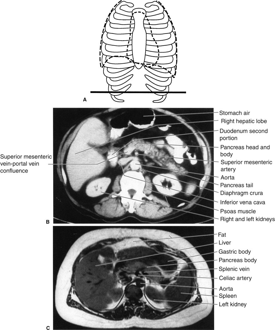
FIGURE 3.36 A: Illustration of the approximate axial anatomic level through the pancreas for B and C. B: Abdomen axial CT image through the pancreas level. Normal. C: Abdomen axial MR image through the pancreas level. Normal.
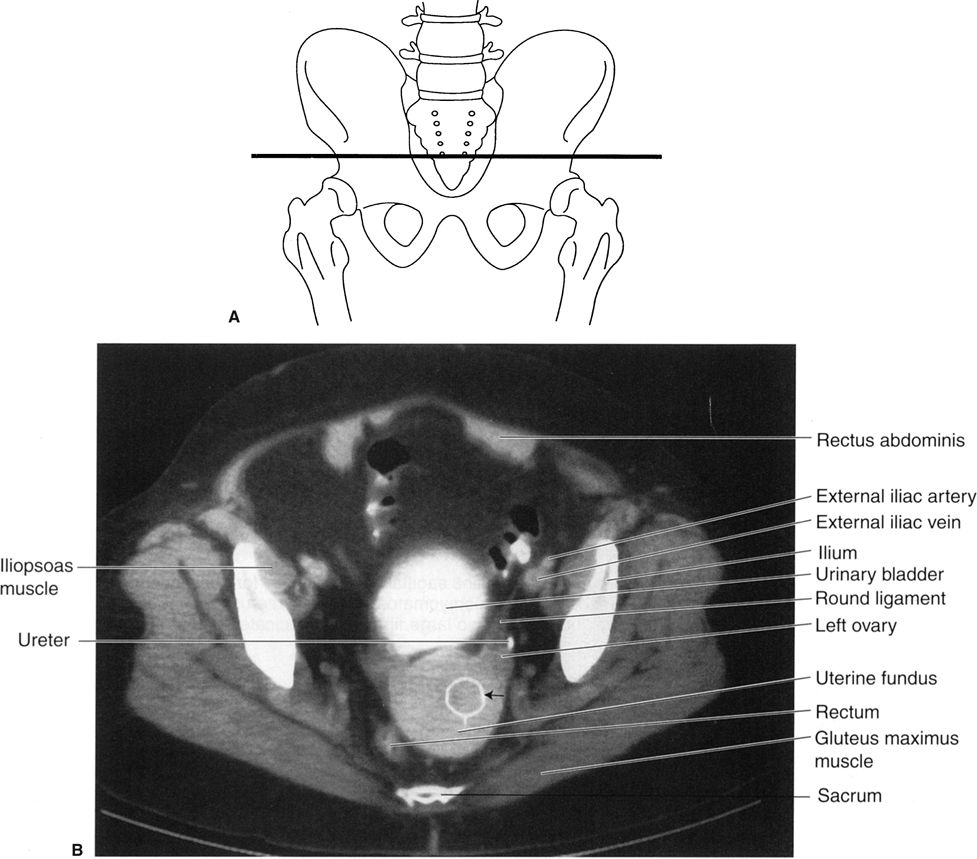
FIGURE 3.37 A: Illustration of the approximate axial anatomic level for B. B: Female pelvis axial CT image through the uterus after intravenous contrast media. Normal. The white metallic density ring (straight arrow) that projects over the uterus is merely a region of interest cursor for measuring tissue density.
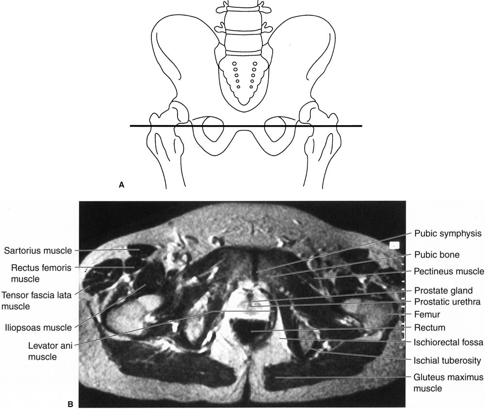
FIGURE 3.38 A: Illustration of the approximate axial anatomic level for B. B: Male pelvis axial T2 MR image at the level of the pubic symphysis and prostate. Normal.
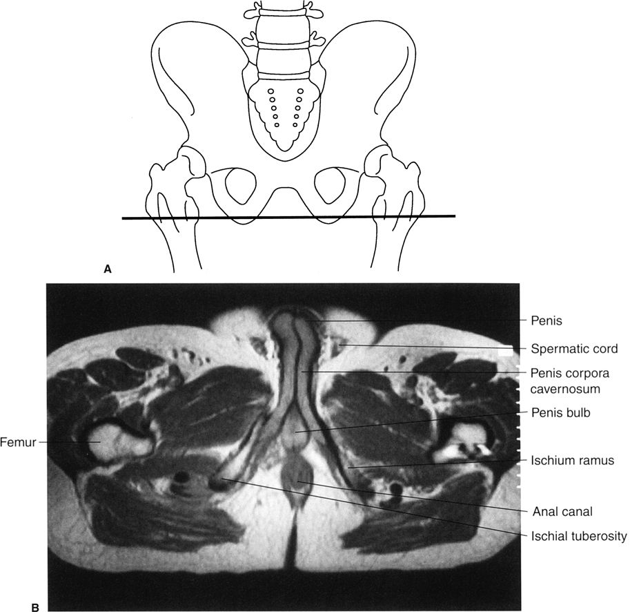
FIGURE 3.39 A: Illustration of the approximate axial anatomic level for B. B: Male pelvis axial T2 MR image at the level of the penile structures. Normal.
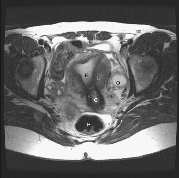
FIGURE 3.40 Female pelvis axial T2 MR image. Same anatomic level as Fig. 3.38 (R, rectum; U, uterine wall; E, endometrial cavity; C, cervix; O, ovary.) (Courtesy of Alan Stolpen, M.D.)
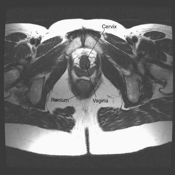
FIGURE 3.41 Female pelvis axial T2 MR image. Same anatomic level as Fig. 3.39. (Courtesy of Alan Stolpen, M.D.)
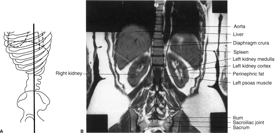
FIGURE 3.42 A: Illustration of the approximate coronal anatomic level through the kidneys for B. B: Abdomen coronal MR image through the kidneys. Normal.
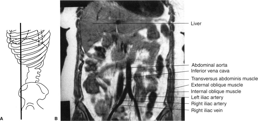
FIGURE 3.43 A: Illustration of the approximate coronal anatomic level through the aorta and inferior vena cava for B. B: Abdomen coronal MR image through the abdominal aorta and inferior vena cava. Normal.
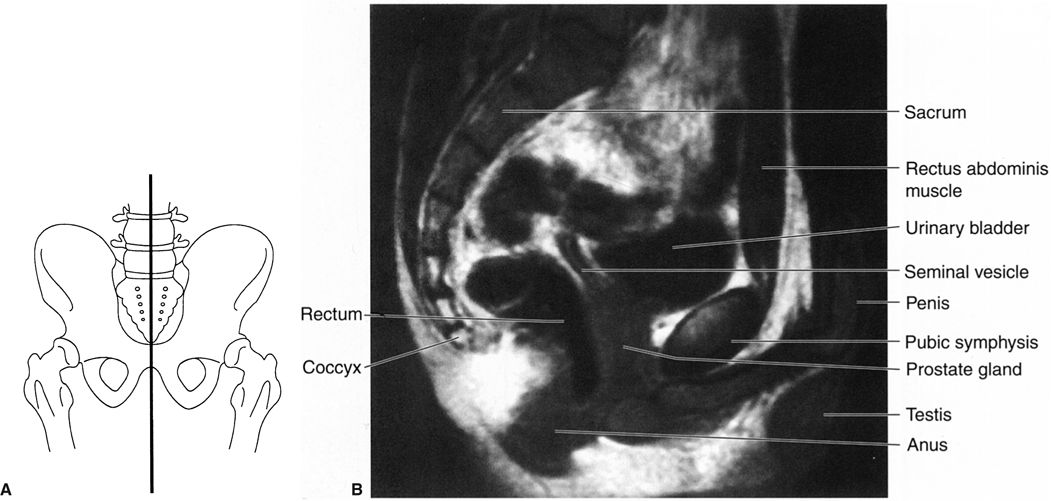
FIGURE 3.44 A: Illustration of the approximate midline sagittal anatomic level for B. B: Male pelvis midline sagittal T2 MR image at the level of the urinary bladder and pubic symphysis. Normal.
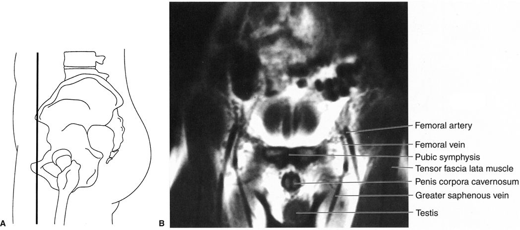
FIGURE 3.45 A: Illustration of the approximate coronal anatomic level for B. B: Male pelvis coronal T1 MR image through the pubic symphysis. Normal.
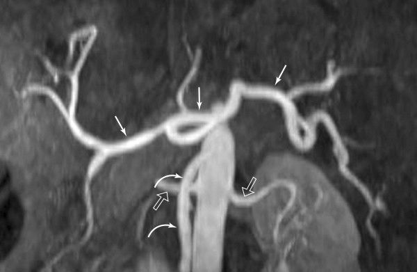
FIGURE 3.46 Magnetic resonance angiography of the upper abdomen. This MR image clearly defines the celiac (straight arrows) and superior mesenteric (curved arrows) arteries and their branches. The origins of the renal arteries (open arrows) from the aorta are noted. (Courtesy of Alan Stolpen, M.D.)
Aortography (catheter injection into the abdominal aorta) and selective arteriography of individual vessels in the abdomen are sometimes performed for diagnostic reasons, particularly in trauma or with GI hemorrhage. With rapid CT imaging, visualization of the arteries and/or veins can be obtained using this modality after intravenous contrast material, thus avoiding the necessity for placing an intra-aortic catheter.
Recall that moving tissue, such as intravascular blood, has less MRI signal than surrounding tissue. Various technical manipulations are possible using this phenomenon, with or without the addition of magnetic contrast material, to allow excellent visualization of almost all of the major abdominal vessels without direct aortic catheterization (Figs 3.46 and 3.47). The choice of CT angiography versus MR angiography is largely dependent on the expertise of the radiologist and the type of equipment available at individual institutions.
Conventional angiography was used in the past to delineate tumors of the solid organs. CT and MRI are now more effective and less invasive methods for characterizing masses.
IMAGING FEATURES OF GASTROINTESTINAL ABNORMALITIES USING TRADITIONAL CONTRAST RADIOGRAPHS
The gut, being a hollow organ extending from the mouth to the anus, has a basic structure and radiographic appearance throughout. If contrast material (barium) fills the gut, one obtains information about the lumen and gut wall. Visualization of the mucosal surface is improved by double-contrast techniques, as barium coating the mucosal surface contrasts with the intraluminal air. Thus, there are only a few basic patterns that are much alike within the esophagus, stomach, and small or large bowel (Fig. 3.48). They are the following:
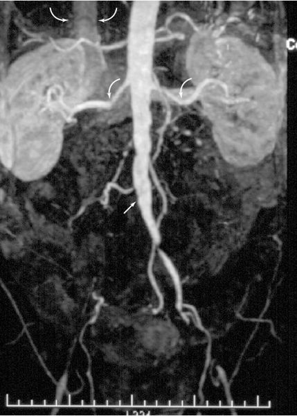
FIGURE 3.47 Magnetic resonance angiography of the aorta and its branches in a patient with arteriosclerosis. The right iliac artery is occluded at its origin (arrow). Both renal arteries (curved arrows) are intact. The inferior vena cava (curved arrows) can be seen. (Courtesy of Alan Stolpen, M.D.)
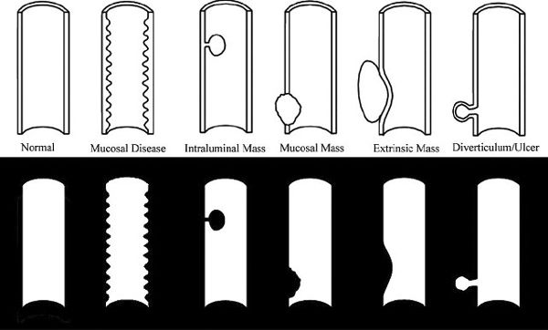
FIGURE 3.48 Types of GI abnormalities (above) and their radiographic appearance (below).
- Intraluminal lesion. Examples include a polyp, foreign body, or exophytic tumor.
- Mucosal diseases. Examples include inflammation of the mucosa and adjacent musculature, indicative of enteritis.
- Mural lesion. The abnormality is in the bowel wall (with or without concomitant mucosal involvement). Examples include tumor, transmucosal inflammation, and edema. If the abnormality encircles the bowel wall (as is often seen in colon cancer), a napkin-ring appearance results.
- Extrinsic lesions. Here, both the bowel wall and lumen are displaced by an extrinsic force. Examples include enlarged mesenteric nodes adjacent to the gut.
- Extraluminal projections beyond the bowel lumen. Typical abnormalities are ulcerations and diverticula.
Symptoms arising from esophageal disease include heartburn and dysphagia (difficulty swallowing). In gastroesophageal reflux disease, common in elderly patients, heartburn and later dysphagia occur, owing to reflux of gastric contents into the esophagus, with resultant esophagitis and eventual stricture. Hiatal hernias often accompany gastroesophageal reflux. The barium esophagram easily detects hiatal hernia and stricture (Fig. 3.49). The esophagram is less sensitive in the diagnosis of esophagitis when compared with endoscopy. Esophageal cancer typically has an intraluminal and an intramural component with abnormal mucosa and narrowing of the esophageal lumen (Fig. 3.50). Esophagography is useful in studying motility disorders of the esophagus.
The majority of upper GI series are performed to detect peptic ulcer disease in either the stomach or duodenum. Clearly protruding from the lumen, ulcers are most easily seen on double- contrast examinations (Fig. 3.51). If seen en face, the ulcer crater appears as a glob of increased density as barium fills the ulcer crater and the lumen is filled with air (Fig. 3.52). Often, mucosal folds radiate toward the ulcer crater, aiding in its detection. With recurrent disease, deformity of the adjacent bowel, particularly in the duodenum, accompanies the ulcer.
Gastric tumors are uncommon in North America. Polyps (Fig. 3.53) are seen in the elderly. Stomach cancer usually appears as an ulcerated, irregular mucosal mass, often accompanied by concentric narrowing of the adjacent stomach.
Localized small bowel disease in North America is most often Crohn disease, which produces inflammation with mucosal ulcerations and thickening of the bowel wall (Fig. 3.54). Other localized lesions and primary small bowel tumors are rare.
A wide variety of metabolic, immune, and other disorders can involve the entire small bowel. The classic example is sprue (gluten hypersensitivity) with associated small bowel dilatation. Dilution of barium and prominence of the mucosal folds are also noted.
Barium enema studies are useful in the workup of inflammatory colon disease. Ulcerative colitis begins in the rectum and extends a variable distance proximally (Fig. 3.55). The mucosal surface shows tiny ulcerations in a uniform nature throughout the affected area, often accompanied by loss of haustrations (the lead pipe colon). Crohn disease affecting the colon (Fig. 3.56) often spares the rectum, skip lesions are common, and deeper ulcerations occur.
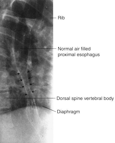
FIGURE 3.49 Double-contrast esophagram. Distal esophageal stricture. The smooth, long, tapered appearance of the narrowed distal esophagus (straight arrows) is typical of a benign stricture owing to reflux of gastric contents into the esophagus.
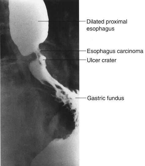
FIGURE 3.50 Barium contrast esophagram. Carcinoma of the esophagus. The cancer produces a narrowed segment with irregular mucosa and ulceration. The proximal esophagus is dilated but otherwise normal.
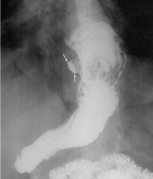
FIGURE 3.51 Gastric ulcer, upper GI series. The lesser curvature ulcer (arrows) protrudes from the stomach lumen.
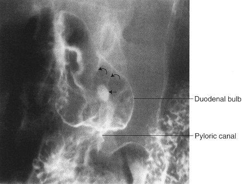
FIGURE 3.52 Double-contrast upper GI series. Central duodenal bulb ulcer (arrow). The duodenal mucosal folds (curved arrows) radiate toward the ulcer crater.
The barium enema, particularly with double-contrast technique, is valuable in detecting colon polyps as well as colon cancer. Intraluminal polyps (Fig. 3.57) are more easily detected than those that are sessile (along the colon wall). Evolution of polyps into colon cancer does occur; the larger the polyp, the greater the chance the histology will show a malignant change. There are approximately 150,000 new cases of carcinoma in the colon and rectum reported each year in the United States. Early detection of this disease improves survival dramatically. As colon cancer progresses in size, it often surrounds the bowel lumen in a fashion described as an apple core or napkin ring (Fig. 3.58). Large advanced cancers are evident on abdominal CT (Fig. 3.59).
There are a number of syndromes characterized by multiple colonic polyps, sometimes with additional polyps of the small bowel or stomach. Prominent among these is familial polyposis of the colon, which is characterized by multiple adenomas, all with malignant potential (Fig. 3.60).
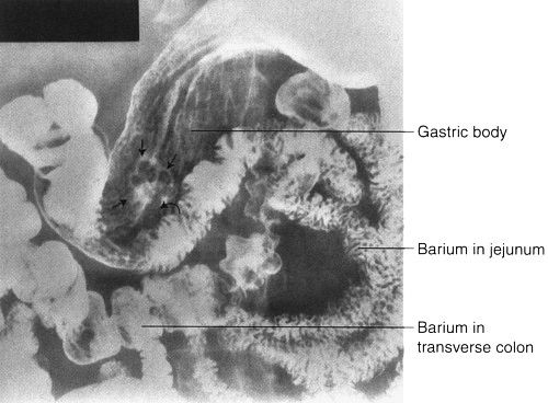
FIGURE 3.53 Double-contrast upper GI series. Gastric polyp. The stalk (curved arrow) of the benign polyp (straight arrows) is clearly visible.
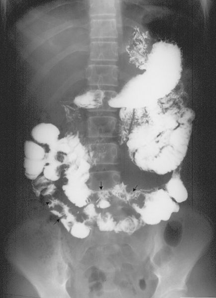
FIGURE 3.54 Crohn disease of the ileum. Antegrade small bowel examination. The affected small bowel (arrows) is narrowed; the adjacent space between small bowel loops indicates bowel wall thickening.
FIGURE 3.55 Ulcerative colitis. Barium enema. The entire colon, except the cecum, is uniformly narrowed, the mucosal surface is irregular, and the overall configuration suggests a lead pipe appearance.
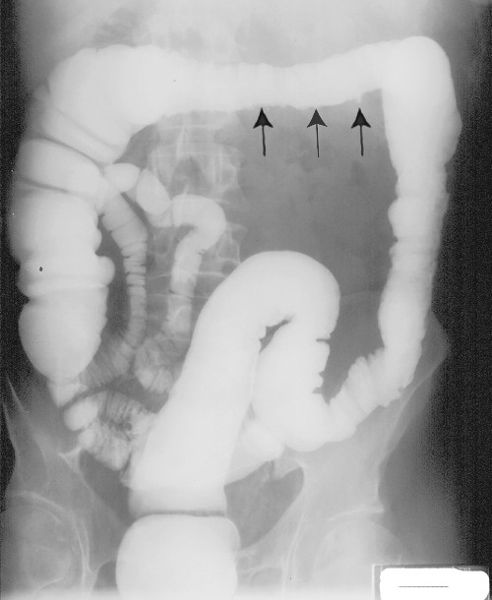
FIGURE 3.56 Crohn disease of the colon. Barium enema. The rectum, sigmoid, and ascending colon are normal. The descending and transverse colon are slightly narrowed, and the mucosa is nodular with small ulcerations (arrows) extending from the colon lumen.
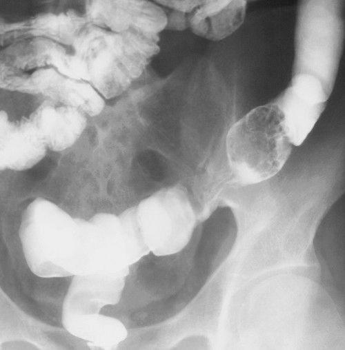
FIGURE 3.57 Barium enema showing villous adenoma with focal carcinoma in the polyp mucosa. A large, lobulated mass fills the lumen of the sigmoid colon.
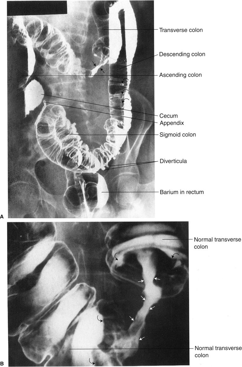
FIGURE 3.58 A: Adenocarcinoma of the transverse colon. Double-contrast colon examination. Note the classic apple core appearance of the colon cancer. The core represents the patent portion of the bowel lumen (straight arrows). Diverticula of the descending colon are seen en face. B: Close-up view of the tumor mass in A. Note the irregular mucosa of the narrowed lumen of the apple core lesion (straight arrows). The mass creates a shouldering (curved arrows) deformity in the neighboring transverse colon both proximally and distally.
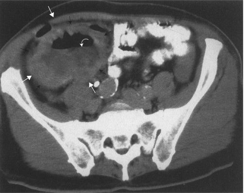
FIGURE 3.59 Lower abdomen axial CT image. The white arrows outline a large cecal neoplasm. The curved arrow show an air–fluid level within the tumor mass secondary to necrosis.
As noted earlier, polyps and tumors of the colon may be identified with virtual colonoscopy (Figs. 3.23 and 3.24).
Acute appendicitis is the most common surgical disease of the abdomen. If clinical history and physical examination are strongly suggestive of appendicitis, further imaging examinations are not needed, as the accuracy of clinical findings approaches 90%. Plain films of the abdomen are not particularly helpful in the diagnosis of appendicitis, unless a calcified appendicolith is noted. Imaging studies are most valuable in those individuals with low to moderate probability of a positive diagnosis (Fig. 3.61). In children, careful US examination performed by a skilled radiologist is frequently the study of choice; CT is sometimes difficult because of the small amount of periappendiceal fat in this age group. In adults, multislice CT of the right lower quadrant, with or without the use of contrast material, is recommended. The abnormal appendix can be identified in most cases as a small tubular structure with distended lumen, thickening of the periappendiceal wall, and inflammation of adjacent fat (Fig. 3.62). One can usually diagnose perforation of the appendix by changes adjacent to the organ.
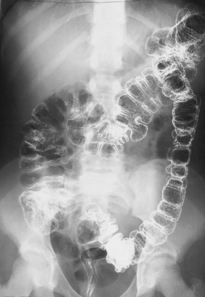
FIGURE 3.60 Familial polyposis of the colon. Double-contrast barium enema. There are innumerable tiny polyps throughout the colon.
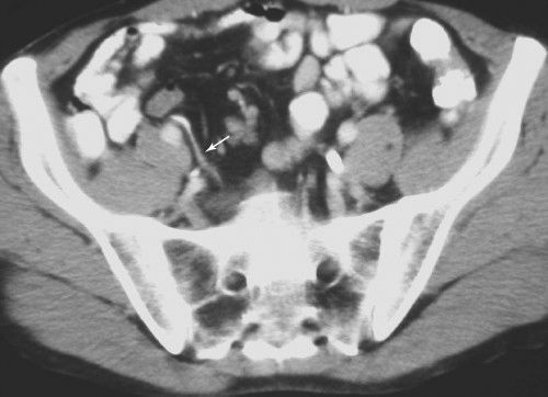
FIGURE 3.61 Normal appendix. Abdominal CT. The appendix is the wormlike, barium-filled density (arrows) in the right lower quadrant. (Courtesy of Bruce Brown, M.D.)
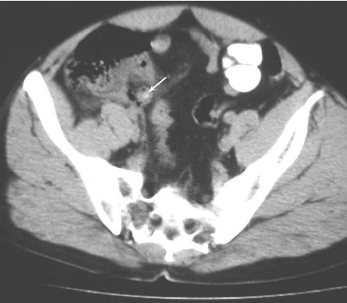
FIGURE 3.62 Abdominal CT transverse view of appendix. Appendicitis with perforation. A calcified appendicolith is in the lumen of the appendix (arrow). There is gas in the appendiceal wall and periappendiceal fluid. (Courtesy of Bruce Brown, M.D.)
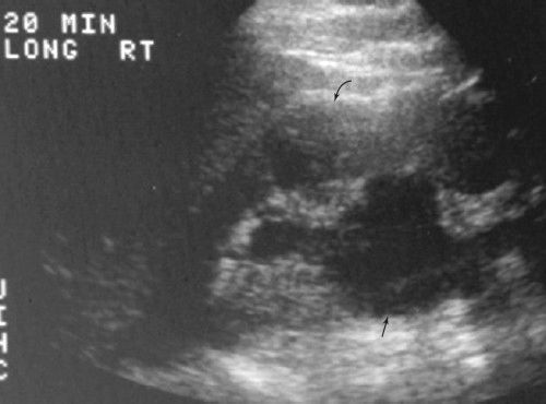
FIGURE 3.63 Unilateral ureteropelvic junction obstruction abdominal sonogram. The echo-free renal pelvis and associated calyces (arrows) are dilated. Renal–cortical borders are outlined by curved arrows. (Courtesy of Monzer Abu-Yousef, M.D.)
IMAGING FEATURES OF GENITOURINARY ABNORMALITIES
Certain anomalies obstruct the flow of urine, producing proximal obstruction. Congenital ureteropelvic junction (UPJ) obstructions can sometimes be diagnosed in utero; less severe cases do not present until later in life. The UPJ obstruction can be unilateral or bilateral. US is an excellent technique for following UPJ obstruction, showing the amount of pelvicalyceal dilatation and its effect on the renal parenchyma (Fig. 3.63). Congenital vesicoureteral junction obstruction is less frequent but usually bilateral (Fig. 3.64).
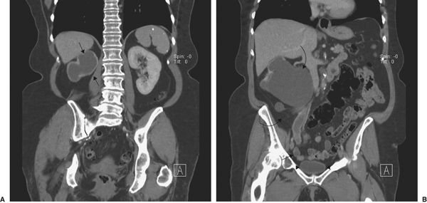
FIGURE 3.64 Unilateral vesicoureteral obstruction. A: Coronal CT. The left kidney is normal, but a urine-filled sac surrounded by renal cortex (arrows) is seen on the left. B: Later coronal CT shows the dilated right renal pelvis (curved arrows) and ureter (straight arrows) extending to the bladder (arrowhead). (Courtesy of Andrew Wu, M.D.)
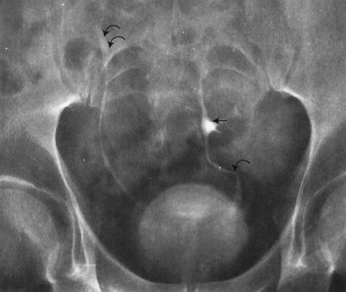
FIGURE 3.65 Abdomen AP EU. Pelvic kidney (simple ectopia). The left kidney is situated in the pelvis, just cephalad to the urinary bladder. The upper collecting system of the pelvic kidney is indicated by the straight arrow. Note the foreshortened left ureter (curved arrow) and the normal right ureter (double curved arrows).
Embryologically, the kidneys develop in the pelvis and migrate cephalad into the abdomen. The kidney that fails to migrate cephalad into the abdomen is called a pelvic kidney, sacral kidney, or simple ectopia (Fig. 3.65). In a horseshoe kidney, the lower poles of the right and left kidneys are connected by a bridge, or isthmus, of renal tissue (Fig. 3.66).
Ureterocele (Fig. 3.67) refers to a dilated intramural ureteral segment that protrudes into the bladder, simulating a cobra’s head. Ureteroceles result from either congenital or acquired stenosis at the ureteral orifice and can cause partial ureteral obstruction.

FIGURE 3.66 Horseshoe kidney. A: The excretory urogram shows the lower pole calyces closer to the midline than those of the upper poles. B: 3-D reconstruction of A shows the fused kidneys (white arrows), both ureters (curved arrows), and bladder (B).

Related posts:
Stay updated, free articles. Join our Telegram channel

Full access? Get Clinical Tree


