Spondylolysis and Spondylolisthesis
Pelvic, Acetabular, and Sacral Fractures
Herniated Intervertebral Disc Disease
Ankylosing Spondylitis, Psoriasis, and Reiter’s Disease
Diffuse Idiopathic Skeletal Hyperostosis
The axial skeleton is the next focus for our consideration. It consists of the skull (which is covered separately), the spine, and the pelvis. It is the main structural support for the body and, as a result, is subjected to many stresses. The spine consists of cervical, thoracic, lumbar, and sacral divisions composed of bones, joints, ligaments, muscular attachments, and nerves. The pelvis articulates with the sacrum on each side, supports many soft tissue structures, articulates with the femurs, and is the proximal attachment for many muscles involved in locomotion.
Back pain is a problem for the majority of our patients at some time in their lives. Most people recover from their back pain with little or no medical care. Occupation-related back injuries are common, and other common etiologies of back pain are listed in Table 6.1. When patients do seek medical care for back pain, radiologic imaging often becomes an important diagnostic tool. Following a thorough history and physical examination, routine anteroposterior (AP) and lateral radiographs often are the first radiologic consultation to be requested to evaluate the symptomatic region of the spine. These images may be supplemented with oblique and coned-down views to better visualize an area, and occasionally lateral flexion and extension views are requested to document spine motion and stability.
Computed tomography (CT) and magnetic resonance imaging (MRI) are extremely useful noninvasive diagnostic tools in visualizing the spine, and their use is increasing while use of the invasive myelogram is decreasing. CT delineates anatomy and pathology more clearly than does myelography. One significant shortcoming of myelography is its inability to demonstrate lateral disc herniations and lateral stenosis. For this reason, CT is obtained following myelography to better delineate the contrast distribution in the dural sac and visualize the intervertebral discs. CT is excellent for bone detail and is useful for diagnosing fractures not visible on plain radiographs as well as better defining the extent of injury. CT is helpful for localizing the exact position of vertebral fracture fragments, particularly important when the fracture fragments are displaced into the spinal canal. Lateral radiographs are used to assess for instability with flexion–extension views. Full series are useful during follow-up of cervical spine injuries, so a thorough understanding of the radiographs remains important. CT is also useful in screening for disc disease and degenerative disease but has largely been replaced by MRI for this purpose. MRI is very good for imaging soft tissues and the bone marrow and allows a wonderful view of the spinal cord and the intervertebral discs. MRI is also used when a spine fracture is present and an associated cord injury is suspected. However, MRI costs approximately twice as much as CT imaging (Table 6.2). In addition, some patients may not be able to have an MRI because the strong magnetic field may disrupt a pacemaker or displace an aneurysm clip, or the patient may not tolerate the relatively confined space.
As previously emphasized in other anatomic regions, a systematic approach for evaluating the spine is needed. You will eventually develop your own system, but the following one will work until you do (Table 6.3). Start with the lateral radiograph (Fig. 6.1A) as it is the most important cervical spine radiograph. Glance at the entire image to see whether something obvious jumps out at you. If it does, put that aside and force yourself to look at the entire study. It is not uncommon to stop looking once one abnormality is found. This can lead to serious consequences! On the lateral radiograph, the normal cervical curve should be mildly convex anteriorly (lordotic). When the patient has pain, straightening of the spine may occur secondary to muscle spasm. A patient in a hard cervical collar also has a straightened curvature. Make note of the normal lines that should be intact on this view (Fig. 6.1B). Now simply count the cervical vertebrae. Things you must see include all seven cervical vertebrae, the entire C7 and T1 intervertebral disc space, and, ideally, the T1 vertebral body. This is especially important in trauma situations as a fracture could be lurking in nonvisualized areas of the spine, and the result could be catastrophic. For example, if the C7 vertebra is not included on the lateral cervical spine radiograph, a fracture of C7 might go unrecognized. An unrecognized and displaced fracture has the potential to cause a serious cord injury. Always gauge the vertical heights of the vertebral bodies and the intervertebral disc spaces. The vertical heights of each vertebral body and intervertebral disc space should be approximately equal to those immediately above and below. Note the osseous densities in general. Some common causes for decreased (osteopenia) and increased bone density are shown in Table 6.4. Metastatic bone disease from prostate, breast, and other malignancies can result in an increased bone density or osteosclerotic appearance.

BACK PAIN ETIOLOGIES
Congenital Meningocele and myelomeningocele Scoliosis Transitional vertebra with pseudarthrosis |
Acquired Arthritis—degenerative, rheumatoid, ankylosing spondylitis Infection—staphylococcus, tuberculosis Metabolic—osteoporosis, osteomalacia, Paget’s disease, sickle cell anemia Neoplasm—benign and malignant primary bone tumors, metastases Trauma—fracture, muscle and ligament injury, spondylolysis, and spondylolisthesis |
Extraspinal Cardiovascular system—referred myocardial pain, aortic aneurysm Gastrointestinal disease Genitourinary system—renal and ureteral pain Muscle strain Psychosomatic or functional |

INDICATIONS FOR THE USE OF IMAGING MODALITIES IN THE SPINE AND PELVIS
Radiographs
Routine Cervical spine—AP and lateral Thoracic spine—AP and lateral Lumbar spine—AP and lateral Pelvis—AP |
Optional when indicated Cervical spine—AP open-mouth view and/or swimmer’s view in trauma, flexion, and extension views for mobility and stability, oblique views for the neural foramina Lumbar spine—flexion and extension views for stability and mobility, oblique views for spondylolysis Sacroiliac joints—oblique views, modified outlet view |
CT Fractures and disc disease |
MRI Soft tissues and bone marrow Spinal cord and disc disease Fractures with suspected cord injury |
Myelogram Disc disease, spinal stenosis, cord, and extradural tumors |

CHECKLIST FOR SPINAL RADIOGRAPH OBSERVATIONS
Lateral radiograph Alignment (three lines in cervical spine) Must visualize seven cervical vertebrae Vertebral body heights Disc space heights Osseous density |
AP radiograph Alignment Vertebral body heights Disc space heights Bone density Pedicles (lower cervical) |

SOME COMMON CAUSES FOR INCREASED AND DECREASED BONE DENSITY
Decreased Osteolytic metastases Osteomalacia Osteomyelitis Osteoporosis Primary bone tumor, especially multiple myeloma Rheumatoid arthritis, ankylosing spondylitis |
Increased Bone infarcts Bone island Callus formation—fractures Endplate sclerosis—disc degeneration Fibrous dysplasia Lymphoma Osteoblastic metastases (prostate and breast) Osteopetrosis Paget’s disease Primary bone tumors (<5% of multiple myeloma) |
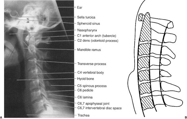
FIGURE 6.1 A: Cervical spine lateral radiograph. Normal. B: Cervical spine lateral illustration. Normal lines found on the normal lateral radiograph.
Next, look at the AP radiograph (Fig. 6.2A) and again check the alignment of the cervical spine. The spine should be straight on this view. Again note the heights of the vertebral bodies and intervertebral disc spaces. When disease or injury is suspected at the C1 and C2 levels, an AP radiograph of the upper cervical spine is obtained by directing the central x-ray beam through the patient’s open mouth. This is called the open-mouth view (Fig. 6.2B), and it allows visualization of the dens, or odontoid process, of the C2 vertebra and the C1 and C2 alignments and joints. An extremely important observation to make is the presence or absence of the vertebral pedicles. Pedicles look like the headlights of the vertebrae in the low cervical, thoracic, and lumbar regions but are obliquely oriented in the upper and mid cervical spine and best seen on cervical oblique views. They are often involved by metastatic disease because of their abundant blood supply. If one or more pedicles are absent, metastatic involvement or some other destructive process must be strongly suspected. There are benign causes such as a meningocele or congenital absence of the pedicle, but these need to be proven rather than assumed.
Occasionally, oblique views (Fig. 6.3) are obtained and the same observations are made as on the other views. The intervertebral foramina, through which the spinal nerves pass, are well seen on these views. Any disease process that narrows the foramina could potentially cause pressure on the nerve exiting through that neural foramen, resulting in radiculopathy, or pain along the distribution of the involved nerve. Some processes that can impinge on the intervertebral foramina include intervertebral disc disease, arthritis, and primary and secondary neoplasms. In the trauma setting, these oblique views allow for evaluation of the facet joints to look for fractures or dislocations.
Lateral flexion and extension views may be necessary to evaluate stability of the spine and assess for ligamentous injury. They should not routinely be obtained when a fracture is present. The majority of motion occurs in the upper cervical spine. When the lower cervical vertebrae cannot be visualized on the lateral view, a swimmer’s view is indicated (Fig. 6.4). CT is often used to diagnose occult cervical spine fractures, determine the extent of fractures, and localize fracture fragments. At many medical centers, severe trauma patients are routinely screened with a CT of the entire cervical spine. The CT data can then be reformatted into coronal and sagittal plane images (see Fig. 6.29B). As already mentioned, MRI is especially useful for evaluating the spinal cord and the intervertebral discs and for assessing ligamentous injury (Fig. 6.5).
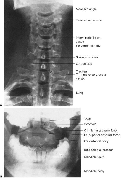
FIGURE 6.2 A: Cervical spine AP radiograph. Normal. B: Cervical spine AP open-mouth radiograph of the upper cervical spine. Normal.
Routine radiographic study of the thoracic spine consists of AP and lateral radiographs (Fig. 6.6). When viewing the thoracic spine, it is easiest to begin with the lateral view and follow the same method of evaluation as used for the lateral cervical spine radiograph. The normal dorsal curve should be mildly convex posterior (kyphotic). Again, assess the vertical heights of the dorsal vertebral bodies and intervertebral disc spaces. As always, check the overall densities of the bones. The lamina and spinous processes are not well seen because the ribs project over them (Fig. 6.6B). It is difficult to number the vertebral bodies without using the anterior view to determine the size of the twelfth ribs.
Next, evaluate the AP thoracic spine radiograph; the spinal alignment should be straight. Assess the vertical height of each dorsal vertebral body and each dorsal intervertebral disc space. The paraspinal line along the left side of the vertebra should be narrow and straight. A focal bulge may be your first indication of a fracture. The pedicles look like headlights on the vertebral bodies, and every attempt should be made to visualize all of them. On AP radiographs, the spinous processes project over the midvertebral bodies at all levels in the spine. Assess the number of rib-bearing vertebra. T12 typically has two short ribs, but transverse processes may instead be present. Similarly, L1 may have rudimentary ribs, so it is important to count from the top down. Occasionally, C7 will have short ribs, but these do not have the typical curved appearance of the true first rib and are usually not a cause of mislabeling. MRI and CT (Fig. 6.7) imaging are useful in the dorsal spine for the same indications as in the cervical spine.
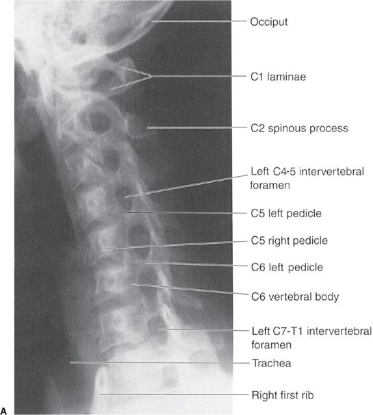

FIGURE 6.3 Cervical spine right (A) and left (B) oblique radiographs. Normal.
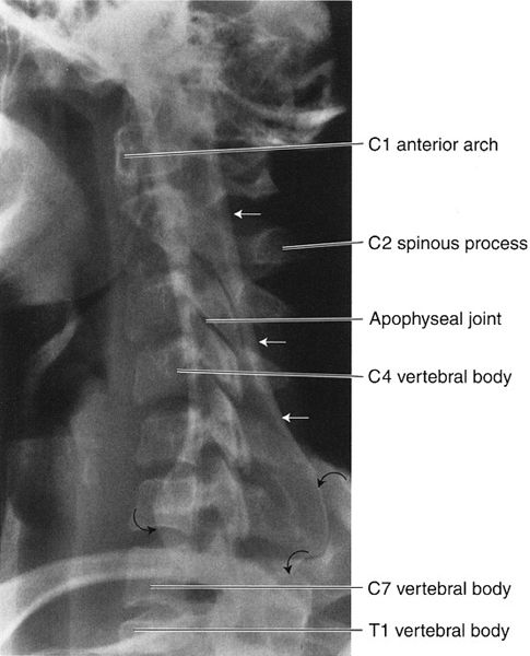
FIGURE 6.4 Cervical spine lateral swimmer’s view. Normal. The patient is almost always radiographed supine with one arm, usually the left, abducted upward alongside the head, whereas the other arm is lowered. This position makes patients appear as if they are swimming the backstroke. The central x-ray beam is directed to the C7-T1 level from the patient’s side on which the arm is lowered, usually the right. The straight arrows indicate the raised arm humerus projecting over the spine. The curved arrows outline the humeral head. Note how well the C7 vertebra is visualized as well as a portion of the T1 vertebra and the apophyseal joints. In this view, it is considered a good technique when you can see the entire C7 vertebra and at least the upper one third of the T1 vertebral body.
Pain in the lumbar spine region is a major cause of disability, lost work time, and health dollar expenditure. The etiology of back pain is complicated, varied, and poorly understood. Following a careful history and physical examination of the lower back, the next step in the evaluation process usually includes radiographs. Routine lumbar radiographs generally consist of AP and lateral views (Fig. 6.8). As previously noted, look first at the lateral view using the same system as described for the lateral cervical and dorsal spine radiographs. In general, note the lumbar spine alignment, which is normally convex anterior (lordotic). When muscle spasm or disease processes are present, this normal curvature may be lost and the spine may appear straight. In addition, observe the overall osseous densities. Next, carefully evaluate the vertical heights of the lumbar vertebral bodies and the intervertebral disc spaces; they should be approximately equal to those immediately above and below but gradually become taller as you progress distally. As a general rule, the L4-5 intervertebral disc space height is greater than the other lumbar disc spaces. If the L4-5 disc space is the same height as those above or below, you should suspect L4-5 disc disease. This also means that the L5-S1 disc level is typically narrower than that at L4-5 and should not be considered abnormal because of decreased height alone. Approximately 15% of the population will have variability in the appearance at the lumbosacral junction. There may be partial or complete lumbarization of S1 or sacralization of L5. Numbering of the lumbar spine can be very difficult, and every attempt should be made to number correctly using chest radiographs if needed to count the number of ribs. It is incorrect to assume that the first non–rib-bearing vertebra on the anterior view is L1 and the vertebra above the sacrum on lateral view is L5. I have seen the same vertebral body numbered differently on the AP and lateral views!
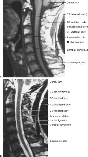
FIGURE 6.5 A: Cervical spine sagittal T1 MR image. Normal. The cerebral spinal fluid is black on a T1 image and white on a T2 image. The bone marrow fat appears whiter (high-intensity signal) on a T1 image than on a T2 image. B: Cervical spine sagittal T2 MR image. Normal.
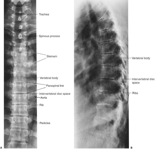
FIGURE 6.6 A: Thoracic spine AP radiograph. Normal. The pedicles on each vertebra have an appearance similar to automobile headlights. B: Thoracic spine lateral radiograph. Normal.
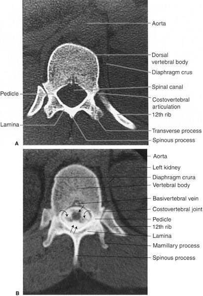
FIGURE 6.7 A: Thoracic spine axial CT image at the T12 level. Normal. B: Thoracic spine axial CT image at the T12 level. Normal. The spinal cord (straight arrow), nerve roots (curved arrows), and the contrast-filled subarachnoid space (double arrows) are well visualized. The contrast media was introduced into the subarachnoid space as part of a myelogram while the CT imaging followed the myelogram. Note how well the osseous structures of the spine are demonstrated.
Always observe the pars interarticularis region of each vertebra for a possible defect; an interruption of bone continuity in the pars interarticularis is abnormal and called spondylolysis. The pars can be seen on lateral view but is difficult on the anterior projection. It is easiest to see on the oblique view. Similar observations are made on the AP radiograph regarding alignment, density, vertical heights of the lumbar vertebral bodies, and the lumbar intervertebral disc spaces. Again, be certain that all of the pedicles are present. Depending on the angulation at L5-S1, it may be difficult to see the L5 pedicles. Occasionally, an angled anterior view is obtained to better evaluate L5 (Fig. 6.9). This view also nicely displays the sacroiliac (SI) joints. Also note that oblique radiographs (Fig. 6.10) are sometimes necessary to better assess the pars interarticularis when spondylolysis is suspected. Once again, the observation checklist for spine radiographs is outlined in Table 6.3.
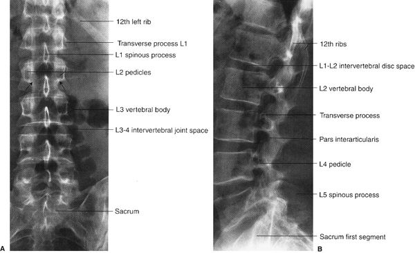
FIGURE 6.8 Lumbar spine AP (A) and lateral (B) radiographs. Normal. The arrows on the AP radiograph indicate the pars interarticularis region.
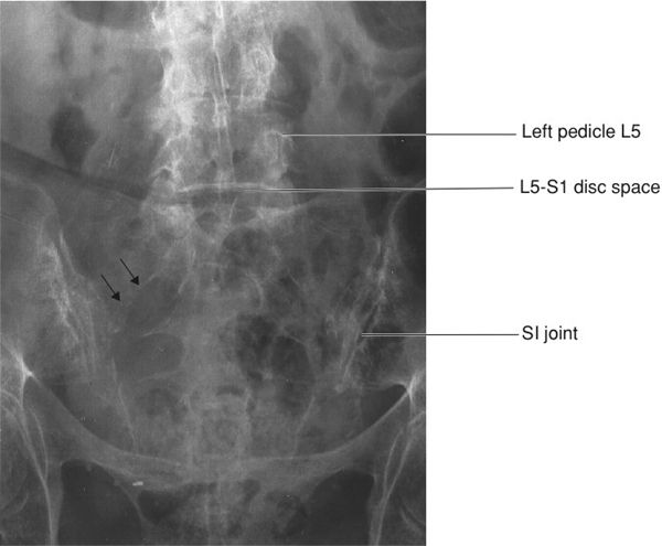
FIGURE 6.9 Lumbar spine angled view of lumbosacral junction. Note how the L5-S1 disc is now easily seen when compared to Fig. 6.8. The facets are prominent because of arthritis. The small straight arrows show the arcuate line of the right S1 anterior sacral foramen.
MRI of the lumbar spine is often requested to evaluate the vertebrae, intervertebral disc spaces, and the spinal cord (Fig. 6.11), which usually ends at the level of L1. As elsewhere in the spine, CT imaging may be requested to determine the presence and extent of fractures and the presence of intervertebral disc disease (Fig. 6.12).
In the past, the myelogram was the gold standard for the diagnosis of disease in and around the neural canal. The myelogram is an invasive procedure that is accompanied by discomfort. It is accomplished by injecting contrast material into the subarachnoid space via a lumbar or cervical puncture, and typical images are shown in Fig. 6.13. Fortunately, water-soluble myelographic contrast agents do not require physical removal as oil-based contrast once did. CT routinely follows the injection to better define the disc and nerve pathology. Understandably, CT and magnetic resonance (MR) examinations are more acceptable to the patient than the invasive spinal puncture associated with myelography.
The sacrum should be evaluated with both the spine and the pelvis, playing a role in both. Unfortunately, it may be difficult to evaluate, especially in an older patient with osteoporosis. The normal sacrum has an anterior concavity and is tilted posteriorly at the L5-S1 junction. The arcuate lines of the neural foramina should be evaluated closely on the AP view. They should be smoothly curved and symmetric (Fig. 6.14). Asymmetry may be the result of fracture or tumor involvement. The SI joints should be evaluated as they are important in the evaluation of several arthritides and may be widened as a result of trauma. Both CT and MRI can be useful in the evaluation of the sacrum and SI joints.

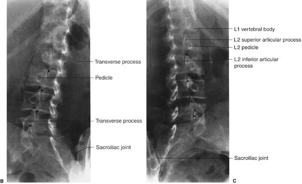
FIGURE 6.10 A: Visible “Scotty dog” and the anatomy that it represents on oblique lumbar spine radiographs. The neck of the Scotty dog represents the pars interarticularis. When the Scotty dog neck is absent, the condition is called spondylolysis. B, C:Lumbar spine right (B) and left (C) oblique radiographs. Normal. Note on these oblique views how well you visualize the normal pars interarticularis or the neck of the Scotty dog (straight arrows) and the normal apophyseal (facet) joints between the superior and inferior articular processes (curved arrows).
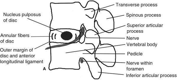
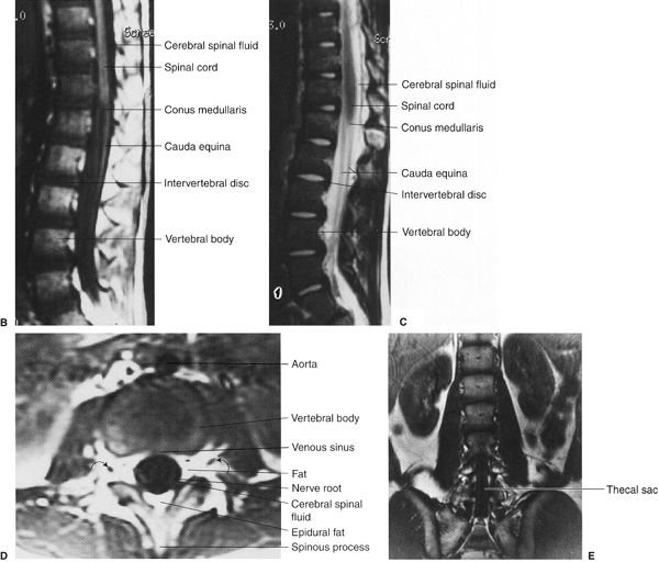
FIGURE 6.11 A: Lumbar spine lateral illustration. Normal. B, C: Lumbar spine T1 (A) and T2 (B) sagittal MR images. Normal. Notice again that the cerebral spinal fluid is black on a T1 image and white on a T2 image. Also, the bone marrow fat is whiter (high-intensity signal) on the T1 image. The intervertebral disc is whiter on the T2 image. D: Lumbar spine T1 axial image. Normal. Note that the nerve roots (curved arrows) are well visualized. E: Lumbar spine T1 coronal MR image. Normal. The coronal plane passes through the upper lumbar vertebral bodies and the lower lumbar neural sac.
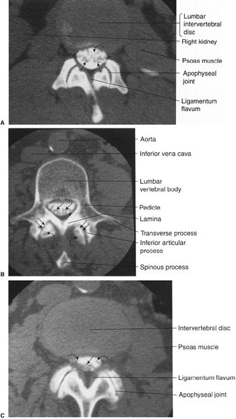
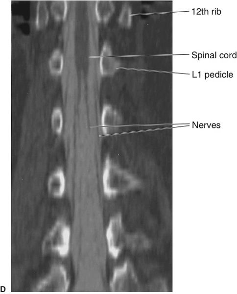
FIGURE 6.12 A: Lumbar spine axial CT image through the L1-2 intervertebral disc level. Normal. The straight arrows indicate the cauda equina surrounded by contrast media in the subarachnoid space cerebral spinal fluid (curved arrow). B: Lumbar spine axial CT image through a lumbar vertebra. Normal. The straight arrows indicate multiple nerve roots. Notice how the inferior articular processes of the vertebra articulate with the superior articular processes (curved arrows) from the vertebra below to form the apophyseal joints (double arrows). C: Lumbar spine axial CT image through a lumbar intervertebral disc. Normal. The straight arrow indicates nerve roots in the posterior aspect of the subarachnoid space, whereas the curved arrows indicate nerve roots about to exit through the neural foramina. D: Lumbar spine coronal reformatted CT. The image was obtained following a myelogram and reformatted through the thecal space. This has a similar appearance to the conventional myelogram radiographs and shows the conus quite well.
An AP pelvis radiograph is the standard view (Fig. 6.15). A lateral view is not obtained, but on occasion up- and down-tilt AP (outlet and inlet) views are indicated to assess fracture displacement. A modified outlet view is also useful for assessing the SI joints. As elsewhere, you must know the anatomy and have a system for looking at the pelvis radiograph. First, look at the sacrum and coccyx followed by the iliac bones bilaterally. Compare the SI joints as they may be narrowed or even absent in diseases like ankylosing spondylitis (see Fig. 6.47C). Then check out the ischial bones bilaterally as well as the pubic rami and the symphysis pubis. Remember that the hamstring muscles arise from the ischial tuberosity; this explains why someone with a hamstring injury runs off the athletic field clutching his or her buttock. As you know, all of the pelvic bones must be evaluated for fractures, density, anomalies, and metastatic lesions.
Anomalies of the spine and pelvis (Table 6.5) vary in severity from mild to severe. As a general rule, most mild spinal anomalies are asymptomatic. Small extra bones or supernumerary bones called accessory ossicles are usually asymptomatic, and they may be located near many different bones including the spine. Examples of accessory ossicles are shown in Fig. 6.16A and B. Accessory ossicles are simply normal variants and should not be confused with a fracture. The smoothly corticated, usually rounded margins help differentiate them from fractures.

A Partial List of Spine and Pelvis Anomalies
Mild Accessory ossicles Cervical ribs Hemivertebra Osteitis condensans ilii Scoliosis Spina bifida Transitional vertebrae |
Severe Absence of the sacrum Meningocele and myelomeningocele Scoliosis Symphysis diastasis |
Occasionally, extra ribs arise from the cervical spine, and they are called cervical ribs (Fig. 6.16C). Cervical ribs are generally asymptomatic but have the potential to cause symptoms secondary to extrinsic pressure on the brachial plexus and the vessels of the upper extremities. A common anomaly at the lumbosacral junction is a transitional vertebra in which the L5 vertebra begins to have the appearance of the sacrum or the sacrum begins to look like a lumbar vertebra. Partial sacralization of L5 is the term used when fusion exists between a portion of the L5 vertebra and the sacrum (Fig. 6.17A). Usually one of the L5 transverse processes is enlarged and fused with the sacrum, but there are many variations. Occasionally, the anatomic L5 is completely sacralized, having the appearance of the first portion of the sacrum. Transitional vertebra may become symptomatic, especially after excessive back strain or when there is a pseudarthrosis (two bones articulating without a joint between them) as seen in Fig. 6.17. A less common anomaly is an abnormal articulation between the C1 spinous process and the occiput (Fig. 6.17B). A more severe anomaly of the spine is total absence of the posterior vertebral arch as in a meningomyelocele.
An important anomaly is spina bifida (Fig. 6.18), which occurs in approximately 5% of the population. Spina bifida occulta is a midline defect of the vertebral arch (usually posterior), and it is generally asymptomatic. When spina bifida has an associated soft tissue mass associated, it is called a meningocele. Meningoceles contain cerebral spinal fluid, and the sac envelope consists of the meninges. When the sac contains spinal cord and/or nerve roots, it is called a myelomeningocele (“myelo-” refers to the cord). A meningocele (Fig. 6.19) is a herniation of neural tissue through a bone defect. The size of these herniations is variable, and the herniation direction most commonly is posterior but can be anterior or lateral. The symptoms vary from nonexistent to extensive and disabling. Visceral innervation of the bladder and/or rectum may be affected as well as sensory and motor nerves. Another unfortunate anomaly in this category is complete absence of the sacrum (sacral agenesis), and it is often associated with a variety of other anomalies. Another severe anomaly is exstrophy of the urinary bladder, which is associated with abnormal widening of the symphysis pubis. This widening of the symphysis pubis, or diastasis, is most often the result of trauma (Fig. 6.20) but can occasionally be associated with a difficult or large baby birth, some bone dysplasias, epispadias, hypospadias, and the prune belly syndrome (loss or absence of abdominal wall muscles).
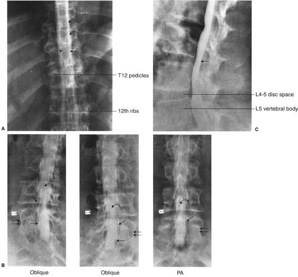
FIGURE 6.13 A: Thoracic spine posteroanterior (PA) myelogram radiograph. Normal. The spinal cord (between the straight arrows) is outlined by the injected subarachnoid contrast media (curved arrows). B: Lumbar spine oblique and PA myelogram radiographs. Normal. The straight arrows indicate the nerve roots surrounded by contrast media exiting the spinal canal. The curved arrows indicate nerve roots within the thecal sac. The double arrows indicate the L5 lumbar vertebra. C: Lumbar spine lateral myelogram radiograph. Normal. The thecal sac contains contrast media (straight arrow).
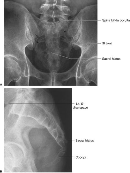
FIGURE 6.14 Sacrum AP with cephalad angulation (A) and lateral (B) radiographs. Normal. The short arrows demonstrate the normal arcuate lines of the anterior openings of the sacral neural foramina. The arrowheads demarcate the posterior margin of the left S1 foramen. There is a spina bifida occulta. The sacral hiatus represents the termination of the posterior elements at the midline.

FIGURE 6.15 Pelvis AP radiograph. Normal.
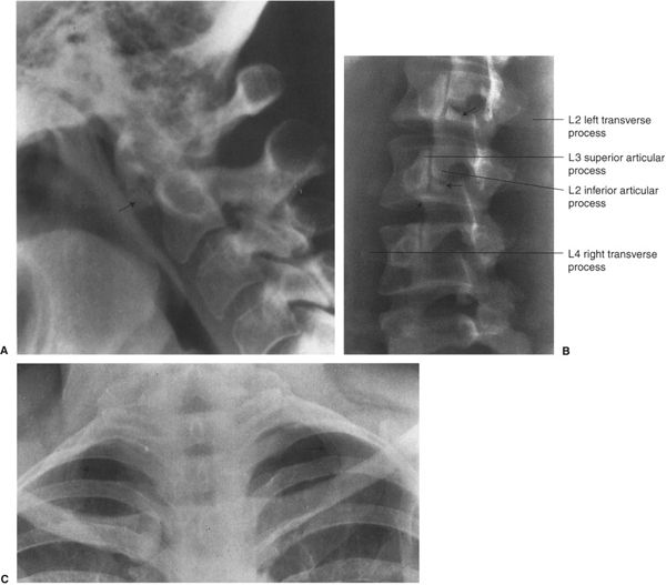
FIGURE 6.16 A: Cervical spine lateral radiograph. This accessory ossicle is located inferior to the anterior arch of the atlas or C1. This supernumerary bone or os (straight arrow) is a normal variant. B: Lumbar spine right oblique radiograph. Lumbar spine accessory ossicles (straight arrows). This 22-year-old gymnast experienced a sudden onset of back pain. The accessory ossicles are variants of normal and had nothing to do with the patient’s back pain. They are usually found around the L2 and L3 levels. C: Lower cervical and upper thoracic spine AP radiograph. Bilateral cervical ribs. The small bilateral ribs (arrows) arise from the C7 vertebra; hence the name cervical ribs.
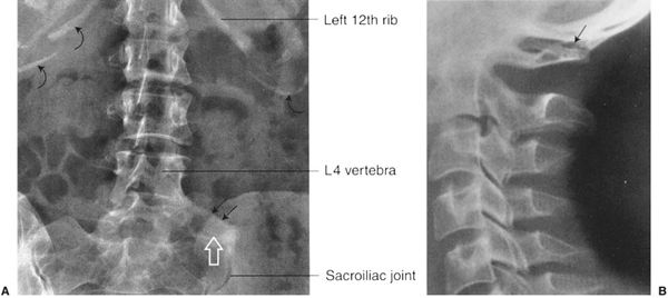
FIGURE 6.17 A: Lumbar spine AP radiograph. Partial sacralization of L5. L5 articulates with the left sacrum in an anomalous fashion (straight arrows). There is a pseudarthrosis (open arrow). Transitional vertebrae describe a situation in which L5 begins to look like a part of the sacrum or the sacrum begins to look like a part of the lumbar spine. The curved arrows indicate calcifications within the cartilaginous portion of the ribs. B: Cervical spine lateral radiograph. Partial occipitalization of C1. The spinous process of C1 articulates with the occiput (arrow). Normally the spinous process of C1 does not articulate with the occiput.
One of the most clinically important anomalies of the spine is scoliosis. Some of the many etiologies of scoliosis include idiopathic, disc degeneration and osteoarthritis, neuromuscular diseases, trauma, infections, tumors, radiation therapy, acromegaly, and underlying congenital problems such as hemivertebrae (Fig. 6.21) and pedicle bars. A hemivertebra is a vertebra with formation of only one side secondary to absence of a lateral ossification center. Typically, there is a body, pedicle, lamina, and corresponding rib on only one side (Fig. 6.22). Pedicle bars occur when two or more pedicles on the same side are joined by a bony bridge. While the normal side grows, the absent side of a hemivertebra or side with a pedicle bar cannot grow as much, and a curvature develops. Approximately 10% of scoliosis cases are congenital with associated vertebral and rib abnormalities as shown in Fig. 6.22, but, by far, most cases are idiopathic (Fig. 6.23). Scoliosis may be associated with abnormalities of the spinal cord, such as a syrinx. When scoliosis is severe or rapidly progressive, it may be treated by fusion of a long segment of the spine (Fig. 6.24). Degenerative lumbar scoliosis (Fig. 6.25) is an increasing problem in the older population. It is likely multifactorial and may be related to altered load due to compression deformities, degenerative disc changes, leg length discrepancies, and lumbosacral anomalies. This deformity may be slow or rapidly progressive and can lead to back pain, radiculopathy, and spinal stenosis. It is occasionally treated by decompression of the stenosis and fusion.
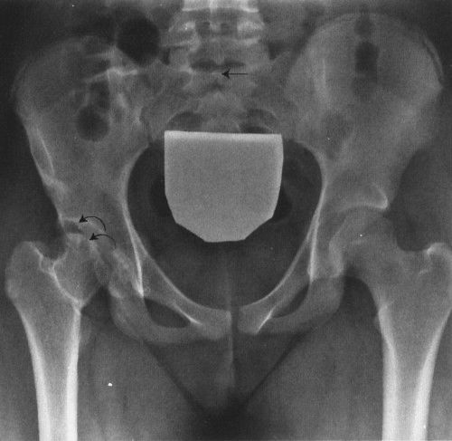
FIGURE 6.18 Pelvis AP radiograph. Spina bifida occulta and developmental dysplasia of the hip. Spina bifida occulta is indicated by the straight arrow and represents incomplete fusion of the posterior sacral segments. Right hip developmental dysplasia (curved arrows) is characterized by the steep slant of the acetabulum compared to the left. The femoral head remodels as it grows in the shallow socket. Note the presence of a gonadal shield.

FIGURE 6.19 A: Pelvis AP radiograph. Sacral meningocele. This 54-year-old patient consulted a physician because of urinary retention. The lucent areas in the sacrum (straight arrows) indicate the bone defect secondary to the meningocele mass. B: Pelvis axial CT image. The full extent of the meningocele mass within the sacrum is indicated by the straight arrows.
Osteitis condensans ilii (Fig. 6.26) is a well-marginated, triangular-shaped area of increased bone density found predominately in women of childbearing years. It is located in the iliac bone just lateral to the SI joint, but the sacrum and SI joints are not involved. This abnormality may or may not be symptomatic. The differential diagnosis should include osteoblastic metastatic disease, ankylosing spondylitis, and other inflammatory arthritides such as rheumatoid arthritis. It usually can be differentiated from metastatic disease that commonly involves multiple widespread sites. The SI joints are usually narrowed or absent in ankylosing spondylitis and often appear irregular in the other inflammatory arthritides such as rheumatoid arthritis.
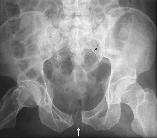
FIGURE 6.20 AP pelvis radiograph. Symphysis pubis diastasis. Widening of the normal close relationship of the left and right pubic bones (white arrow) is due to trauma in this patient. Note the irregular margin from fracture of the right side of the symphysis. The disrupted arcuate line of the left sacral foramen (arrow) should be searched for since the pelvic “ring” typically breaks in at least two places.
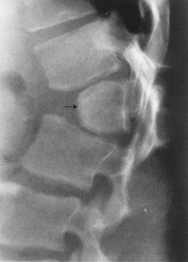
FIGURE 6.21 Lumbar spine lateral radiograph. L1 posterior hemivertebra (arrow). This is usually asymptomatic.
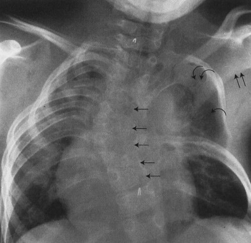
FIGURE 6.22 Thoracic spine AP radiograph. Congenital scoliosis. The thoracic spine is convex to the right, and the thorax is markedly asymmetric. Underlying the scoliosis are multiple hemivertebrae or incompletely formed thoracic vertebrae (straight arrows). There are multiple absent left ribs (curved arrow), and several left upper ribs are fused (double curved arrows). The left scapula is abnormally elevated (double straight arrows).
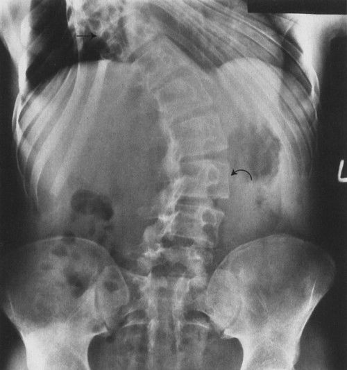
FIGURE 6.23 Thoracolumbar spine AP radiograph. Idiopathic scoliosis of the thoracic and lumbar spine. The lumbar spine is convex to the left (curved arrow), and the lumbar vertebrae are markedly rotated. This rotation component causes the lumbar vertebra to appear oblique on the radiograph. The lower thoracic spine is convex to the right (straight arrow), resulting in asymmetry of the ribs and thorax. Interestingly, the foramen magnum and sacrum usually form a vertical line when a line connects the two.
A sometimes confusing variant in the pelvis is os acetabulare. This is an accessory center of ossification at the superolateral margin of the acetabulum (Fig. 6.27). It is typically triangular in shape. The margins are smooth and corticated, which should allow differentiation from a fracture.
Fractures of the spine and pelvis are common and result from a wide variety of traumas including motor vehicle accidents, sports, falls, and normal activity in those who have osteoporosis or bone loss due to tumor. Fractures of the spine are obviously important as the spinal cord and cauda equina are vulnerable to injury because of their close proximity to the vertebrae. Roughly 40% of cervical spine fractures have neurologic complications, 10% in the thoracic spine and 4% at the thoracolumbar junction.

FIGURE 6.24 AP (A) and lateral (B) thoracolumbar radiographs. Posterior spinal fusion for idiopathic scoliosis. Fusion rods, screws, and hooks are used to decrease the curvature. Bone graft is usually placed as well to prevent progression of the curves.
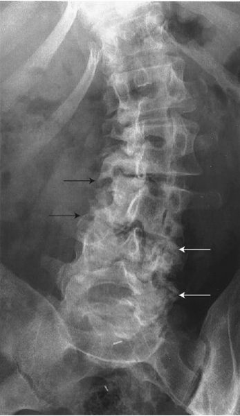
FIGURE 6.25 Lumbar spine AP radiograph. Senile scoliosis. The lumbar spine is convex to the left. The discs are asymmetrically narrowed and there is prominent osteoarthritis of facets (arrows), which is worse on the concave sides.

FIGURE 6.26 Pelvis AP radiograph. Osteitis condensans ilii. The sharply marginated, bilateral increased densities (sclerosis) involve the iliac sides of the sacroiliac joints and spare the sacrum. This is a benign condition that is usually found in women in their childbearing years and seldom found in older women. This can be an incidental finding on a radiograph, or the patient may present with acute or chronic back pain.

FIGURE 6.27 Hip AP radiograph. Os acetabulare. The smoothly marginated, oval density near the superolateral margin of the acetabulum (arrow) is a normal variant and should not be confused with a fracture.
Most cervical spine fractures occur between C5 and C7, with another peak at C1 and 2. A variety of injuries occur when the cervical spine undergoes acute hyperflexion and hyperextension (Table 6.6). The flexion teardrop fracture (Fig. 6.28) is one type of injury that results from acute cervical spine hyperflexion. The teardrop-shaped fracture fragment is the result of compression at the anterior inferior aspect of the vertebral body. This fracture is usually accompanied by disruption of the interspinal ligaments between the spinous processes, thus making the spine very unstable. Other ligaments that may be involved are the supraspinous ligament and the ligamentum flavum. The involved vertebral body may be displaced posteriorly, and this situation is a good indication for CT imaging to determine the extent of the fracture lines and to determine the precise location of the fracture fragments, especially their relationship to the cervical spinal cord. Particularly with neurologic deficit, MRI may be used to evaluate the spinal cord for injury and the soft tissue structures such as the ligamentum flavum and interspinous ligaments.
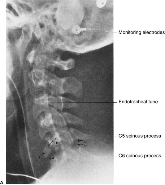
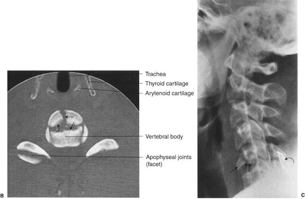
FIGURE 6.28 A: Lateral cervical spine radiograph. C5 flexion teardrop fracture. This 21-year-old man was involved in a motor vehicle accident. There is mild compression anteriorly of the C5 vertebral body secondary to the comminuted fracture (straight arrows), and there is mild separation of the fracture fragments. The major fracture fragment has a teardrop shape (curved arrow) due to avulsion at the site of the anterior longitudinal ligament. The hyperflexion injury has resulted in a mild separation or fanning of the space between the C5 and the C6 spinous processes secondary to ligamentous disruption (double curved arrows). The disrupted ligaments are the interspinal and supraspinal ligaments and possibly the ligamentum flavum. Also, the hyperflexion injury created minimal widening of the C5-C6 disc space (double straight arrows) and mild angulation of the spine at this level with minimal retrolisthesis of C5 on C6. This type of cervical fracture is usually associated with severe cord injury as the vertebral body is often displaced posteriorly into the spinal canal. B: Cervical spine axial CT image of the C5 vertebra. The comminuted fracture lines in the vertebral body are separated or distracted (straight arrows), and the anterior fracture fragments are displaced anteriorly approximately 3 mm (curved arrow). C: Lateral cervical spine radiograph. Posterior wire stabilization of the cervical spine between the spinous processes of C5 and C6 vertebrae (curved arrow). The major fracture fragment (straight arrow) is in fairly good alignment with mild offset of the fragments (double straight arrows), but no attempt is made to reduce this fragment.
Facet locking (Fig. 6.29) is another hyperflexion injury. Locking will occur when the inferior articular process of the upper vertebra moves forward or anteriorly over the superior articular process of the lower vertebra, which results in an anterior dislocation of the upper vertebra. Once again, the spine is unstable as there usually is posterior and sometimes anterior ligamentous disruption, and cervical spinal cord injury is common. The lateral radiograph is usually sufficient to make the diagnosis (see Fig. 6.29A), but occasionally a reconstructed sagittal CT image (Fig. 6.29B, C) is necessary to confirm the diagnosis. Unilateral locked facet (Fig. 6.29C) has a rotational component and does not have the extensive ligamentous disruption as the bilateral form does. Unilateral facet fracture-dislocation may be a difficult diagnosis since there is less displacement as a result of the fracture of the superior articular process. The rotational component may not be manifest until later and should be looked for on subsequent radiographs (Fig. 6.30A–C).

Related posts:

Stay updated, free articles. Join our Telegram channel

Full access? Get Clinical Tree


