WILLIAM E. ERKONEN AND BRAD H. THOMPSON
How to View the Frontal Chest Radiograph (Posteroanterior and Anteroposterior)
How to View the Lateral Chest Radiograph
Anteroposterior Lordotic Chest
Normal Thoracic Sectional Anatomy
Cardiac Computed Tomography Imaging
Confusing Extrathoracic Conditions
Foreign Bodies, Lines, and Tubes
Other Air Accumulations in and Around the Chest
Atelectasis, Pulmonary Emboli, and Infections
Approach to a Pulmonary Nodule
Mediastinal Compartments and Lesions
Aneurysms, Enlarged Vessels, and Vascular Calcifications
Chest pain, shortness of breath, and pneumonia are common presenting complaints for patients seeking medical care, especially through the emergency department. The workup or investigation of these symptoms usually necessitates an initial investigation with a chest radiograph. Therefore, it is not surprising that chest radiographs are by far the most commonly ordered examinations by family physicians and emergency room clinicians. Since all primary care physicians should be adept and comfortable reviewing chest films, it is our goal through this chapter to provide a primer on how to logically approach chest radiographs and to discuss those disease processes that are commonly encountered in daily practice.
The chest radiographic examination is best accomplished within the radiology department, and a routine study consists of posteroanterior (PA) and lateral views. When the patient’s condition precludes these routine views, a single portable anteroposterior (AP) view can be obtained. AP films can also be performed portably on those individuals unable to ambulate. It should be realized that portable films do not include lateral projections, which decrease sensitivity for detecting chest disease, and are also necessarily fraught with numerous technical limitations such as artificial cardiac magnification. For these reasons, every attempt should be made to request PA and lateral radiographs whenever possible. Illustrations for these radiographic techniques have been previously demonstrated in Chapter 1 (Figs. 1.1 to 1.4).
Chest radiographs are solely designed to provide optimal detailed information about the lungs and are not indicated for evaluation of suspected problems of ribs, shoulders, or the thoracic spine. In practice, one of the most common mistakes that occurs daily is the inappropriate request to evaluate for bony abnormalities such as rib fractures with chest films. These structures are poorly delineated on chest films and require formal dedicated radiographs in an effort to adequately evaluate these structures. Fortunately, the amount of radiation required for a routine two view radiological chest examination is small and not a threat to the patient. A routine plain film radiographic examination of the chest exposes the patient to 0.1 millisieverts (mSv) of radiation, which is similar to 10 days’ exposure to environmental background radiation. In comparison, the dose of a standard chest computed tomography (CT) is 8 mSv, which is comparable to 3 years’ exposure to natural background radiation.
HOW TO VIEW THE FRONTAL CHEST RADIOGRAPH (POSTEROANTERIOR AND ANTEROPOSTERIOR)
The first step in reviewing chest films is orienting the radiographs correctly on the viewbox. There is nothing more embarrassing than watching a novice pontificate over a set of chest radiographs that are either upside down or reversed. A significant part of the art and practice of medicine is just learning the jargon, lingo, routines, and rituals. Fortunately, with the advent of digital radiography and picture and archive systems (PACS), the examinations are usually displayed correctly on computer-viewing stations.

FIGURE 2.1 The correct positioning of a chest radiograph on a viewbox. The patient’s right side on the film should always be opposite the viewer’s left side.
Obviously, the right (R) and left (L) markers on the film indicate the patient’s right and left side, respectively. The PA film should be hung as if you are looking at the patient such that the (R) film marker is opposite your left side (Fig. 2.1). This approach applies to all frontal projection chest radiographs (either AP or PA views). Of course, the patient’s head should be oriented at the top of the radiograph. The next and perhaps most critical step is making sure that the films are annotated with the correct name. Needless to say, it would be malpractice to render a film interpretation and initiate treatment on the wrong patient. Next, critique the film for quality and for positioning errors. Poor film quality will only significantly hamper your diagnostic success.
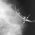
When first reviewing chest films, we suggest the observer to render an initial gestalt impression by casually glancing over the entire image for any obvious abnormality that might be readily apparent, such as an enlarged heart or a baseball-sized lung mass. Remember always to look at all four corners of the image. Once this is performed, we suggest reviewing the films in a logical and thoughtful manner, using a methodical approach. Unfortunately, there is no single generally accepted or standardized system for evaluating a chest radiograph, so we advise developing your own comfortable system that can be used consistently for each and every study. Remember, all commercial pilots use a standard checklist prior to takeoff, which includes making sure that there is sufficient fuel, all equipment is functionally operational, and instruments are correctly set for departure. Knowing the likelihood of human error, commercial airlines consider such checklists critical for maintaining air safety. The same principle should apply to chest film interpretations as well.
A mental checklist or system is desirable when reviewing chest radiographs. So, program your internal computer to operate with a systematic checklist to avoid overlooking important areas or structures, as many of the errors made in medicine are errors of omission. Experimental perception studies using retinal tracking have investigated the process of film visual interrogation for experienced and inexperienced reviewers. The arrows in Fig. 2.2A roughly approximate the visual pathway used by a novice viewing a chest radiograph. In practice, film review by the inexperienced is random and quite haphazard, often resulting in significant omissions. If you persist with this rookie approach, errors are inevitable! The arrows on Fig. 2.2B on the other hand, demonstrate a deliberate visual approach characteristic of experienced reviewers, making sure all regions of the film are visually inspected. Because of experience and practice, radiologists generally review radiographs using more of a generalized or gestalt approach, implementing a more circumferential and highly efficient visual pathway.

FIGURE 2.2 Illustration of a probable eye search pattern of a rookie (A) and by someone with a systematic approach (B) to a radiograph. Note that the rookie’s search pattern is highly disorganized.
A common question relates to how long it should take to thoroughly inspect a set of chest films. While there are no correct answers, the time required to completely interrogate a film largely depends on experience. For novices, sufficient time should be around 20 seconds. In comparison, experienced reviewers can accurately review a film in a matter of seconds. It should be pointed out that excessive time spent looking at films only increases the likelihood of false-positive findings, that is, erroneously “identifying” lesions that do not exist. This phenomenon occurs for all reviewers regardless of experience. Staring at films rarely improves one’s perception. One important caveat that is worth remembering is that “you only see what you know.” Lack of knowledge about chest anatomy and normal radiographic findings will only limit your success in film interpretation.
The following system is suggested which can be used for a lifetime, or until you develop the requisite experience and skill to modify this approach. In developing a standardized approach, we find it useful to start at the top of the film to make sure the tracheal air column is midline. This accomplishes two missions: first, the tracheal air column should be midline and superimposed over the thoracic spine. This ensures that there is no appreciable malpositioning of the patient (Fig. 2.3). Second, deviation of the trachea implies mass effect usually by thyroid enlargement. This finding is quite common and usually missed in daily practice. Next, follow the trachea inferiorly to arrive at the cardiac shadow, rendering an impression about the overall heart size. The transverse diameter of the cardiac silhouette should not exceed 50% of the transverse diameter of the thoracic cage measured or estimated at the same level. This is called the cardiothoracic ratio (Fig. 2.4). This measurement, however, applies only to PA films as there is considerable magnification of the cardiac silhouette on AP films. By convention, PA films are preferred since this technique has the heart closest to the film thereby limiting the degree of artificial magnification. The greater the distance between an anatomic structure and the radiographic film, the greater the magnification. As a useful analogy, consider the shadow cast by your hand from a light source. If we consider a flashlight as the x-ray source and the ceiling as the film, the closer the hand is to the ceiling, the more accurate the size of the shadow. Also, remember that diaphragmatic elevation as occurs commonly in shallow inspiration also tends to make the heart more horizontal and larger than it really is. With experience, cardiac size rarely requires actual determination of the cardiothoracic ratio. You should be able to quickly ascertain whether the cardiac silhouette is normal or not with just a little practice.

FIGURE 2.3 Chest PA radiograph. Normal. The vertical air density trachea (straight arrows) should always be midline. The narrow mediastinum is water density (curved arrows).
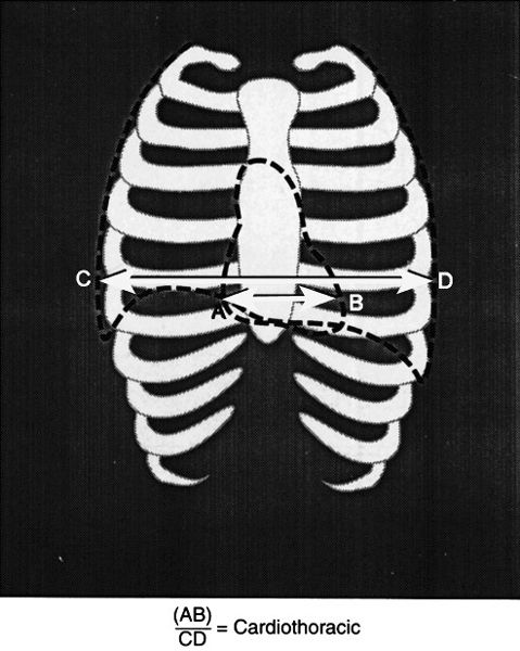
FIGURE 2.4 Method for determining the cardiothoracic ratio. The cardiothoracic ratio is calculated by measuring the transverse diameter of the heart (B) and dividing by the transverse thoracic measurement CD.
Next, evaluate the cardiac shape. What actually determines the cardiac shape? The convex right cardiac border is formed by the right atrial shadow, residing just superior is a vertical straight border rendered by the superior vena cava (Fig. 2.5, see Fig. 2.38A). The left ventricle constitutes the left heart border and cardiac apex. The superior left cardiac border should be concave in most cases (Fig. 2.5). The right ventricle is directly superimposed on the cardiac silhouette and is not a border-forming structure on frontal radiographs. Similarly, a normal sized left atrium is also not visible on PA or AP radiographs (Fig. 2.6). In cases of left atrial enlargement, the superior left heart border becomes convex, and in severe cases, the right lateral edge of the left atrium may become superimposed over the right atrial shadow, producing what is known as the double-density sign (see Fig. 2.69A). As the left ventricle enlarges, the cardiac apex moves to the down and out. As the right atrium enlarges, the right heart border becomes protuberant (Fig. 2.7).
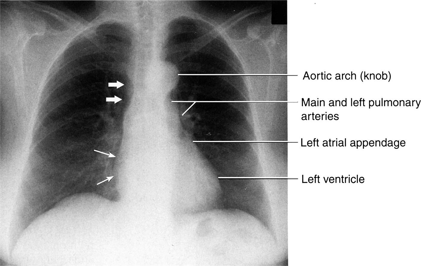
FIGURE 2.5 Chest posteroanterior (PA) radiograph. Normal. The convex right cardiac border is formed by the right atrium (straight thin arrows), and the heavy arrows indicate the location of the superior vena cava. The left cardiac and great vessels border might be considered as four skiing moguls. From cephalad to caudad the moguls are the aortic arch, the main and left pulmonary arteries, the left atrial appendage, and the left ventricle.
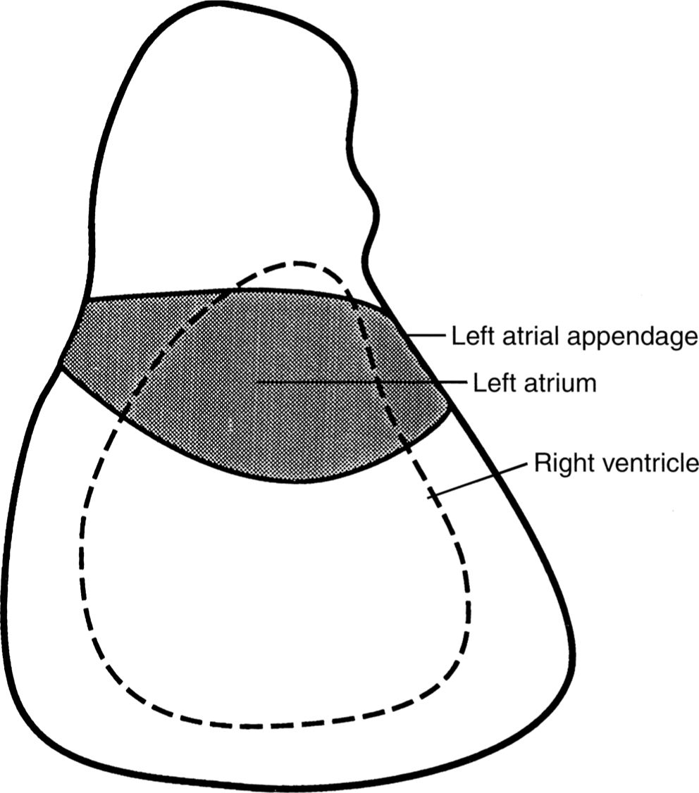
FIGURE 2.6 The approximate location of the left atrium and right ventricle on a normal PA or AP chest radiograph. These cardiac chambers cannot be delineated on normal studies. However, the left atrial appendage can occasionally be seen in normal hearts.
Next, your visual pathway should take you superiorly to the aortic arch (knob), pulmonary arteries, and the main stem bronchi. The left and right pulmonary arteries and the main stem bronchi form the hilar shadows (Fig. 2.8). On normal chest radiographs, the left hilum is more cephalad than the right hilum approximately 70% of the time and is at the same level in 30% of normal subjects. The normal right hilum should never be cephalad to the left hilum. The pulmonary arteries and their lobar branches emanate outward from the hili. The main pulmonary artery segment tends to be more prominent in the young and athletic, especially in females, but this prominence usually disappears with age. The aortopulmonary window is the concavity or space immediately below the aortic arch knob and just above the left pulmonary artery shadow (Fig. 2.9). Convexity of the aortopulmonary window raises the suspicion of either a mass or adenopathy occupying this space. It is important to remember that in the elderly the thoracic aorta commonly becomes tortuous or ectatic, and this should not be interpreted as abnormal.
Now your gaze should be directed to the mediastinum and evaluate it for widening; however, this may take some experience. Also, remember that on recumbent portable films the mediastinum likely will be wider in appearance than it would be on an upright film. Most of the mediastinum shadow is caused by the great vessels and the vascular pedicle. The vascular pedicle extends from the thoracic inlet cephalad to the base of the heart caudally. The right border of the pedicle is the superior vena cava, and the left border is the aortic knob near the origin of the left subclavian artery (Fig. 2.3, see Fig. 2.68D). Now divide the lungs into horizontal thirds and compare the right and left lung fields for symmetry (Fig. 2.9). Next, evaluate the sharply demarcated domed diaphragms; the right hemidiaphragm should normally be about 1 to 2 cm higher than the left. This mild elevation is due to the liver, which resides immediately inferiorly. The lateral recesses of the diaphragms form the lateral costophrenic angles, which should be sharp and form an acute angle where the diaphragms insert laterally to the chest wall. Finally, determine the location of the gastric air bubble, which should reside immediately underneath the left hemidiaphragm on an upright film (Fig. 2.10).

FIGURE 2.7 Cardiac silhouette changes during right atrium and left ventricle enlargement. As the right atrium enlarges, the convex right heart border enlarges to the patient’s right. As the left ventricle enlarges, the cardiac apex moves to the patient’s left and downward.
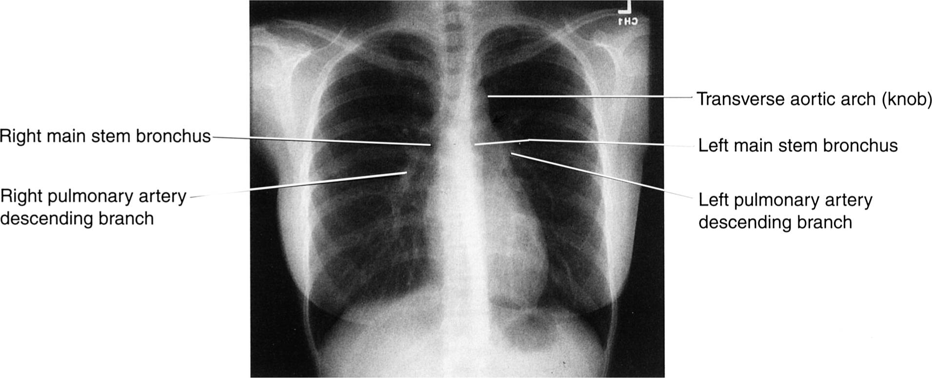
FIGURE 2.8 Chest PA radiograph. Normal. It is important to note that the air-filled main stem bronchi appear black, whereas the blood-filled pulmonary arteries appear white. See Table 1.1 in Chapter 1.

FIGURE 2.9 Chest PA radiograph. Normal. Divide the PA or AP chest radiograph into horizontal thirds and compare the right and left lung fields moving in a head-to-foot direction. Note the aortopulmonary window (straight arrow).
Although the osseous structures are not well delineated on chest radiographs, significant abnormalities can occasionally be identified and should be detected if at all possible. As part of a routine chest film, exposure should allow the reviewer a cursory evaluation of the lower cervical spine, thoracic spine, and ribs (Figs. 2.10 and 2.11). Ribs are difficult to evaluate, so you need to trace each one visually or use your fingertip. On a PA radiograph, the horizontal portions of each rib are the posterior arcs and the anterior ribs are usually angled downward (Fig. 2.11). Portions of the shoulder girdle are usually included in the field of view and can be evaluated without much difficulty. As always, you should compare the right and left sides of the chest for symmetry.
HOW TO VIEW THE LATERAL CHEST RADIOGRAPH
Now position the lateral chest radiograph on the viewbox with the patient’s head oriented to the top of the film. There is no hard-and-fast rule about the direction that the patient should be facing, but by convention it is customary to have the patient facing left (Fig. 2.12). Once again, begin the radiograph evaluation by casually viewing the entire image looking for any obvious abnormality. As on PA and AP radiographs, begin by estimating the size and shape of the cardiac shadow, which lies anteriorly in the chest cavity. On the lateral projection, the right ventricle forms the anterior border of the cardiac silhouette. The left ventricle forms the major portion of the inferior–posterior cardiac border, and the left atrium forms the superior–posterior cardiac border (see Fig. 2.12). On most lateral chest radiographs, the posterior wall of the inferior vena cava (straight arrows) can be seen as it enters from the abdomen in to the right atrium (Fig. 2.12). The identification of the inferior vena cava is useful to determine left ventricular size. The left ventricle is considered enlarged when the left ventricular posterior edge is 2 cm or more posterior to the inferior vena cava. The right atrium is a superimposed chamber and is not visualized on the lateral projection.
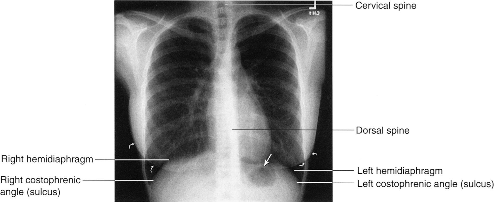
FIGURE 2.10 Chest PA radiograph. Normal. After comparing the lung fields, you next view the diaphragms, costophrenic angles, and lower dorsal spine. Note the close proximity of the gastric fundus air to the left hemidiaphragm (arrow). Always remember to identify the breast shadows in female patients (curved arrows).
The lateral film is the best view to evaluate the hila. By drawing a vertical line down the tracheal air column, the hila can be separated into left and right. The dominant shadow ventral to your line is largely composed of the right main pulmonary artery, which should be about the size of your thumbprint. The left hilum, composed of the left pulmonary artery, resides posterior to the line and should be about one third the size of the right (Fig. 2.13). Then observe the sternum and search the retrosternal and retrocardiac spaces for abnormal or pathologic water or air shadows (Fig. 2.14A). On the lateral view, the retrosternal lucency primarily reflects the pneumatized upper lobes, whereas the right middle lobe and the lingular segments of the left upper lobe project over the cardiac silhouette. The lower lobes are located in the retrocardiac space overlying the spine extending inferiorly to abut the diaphragms (Fig. 2.14B). It is important to understand the pulmonary lobar spatial relationships to assist in locating pathologic pulmonary processes.
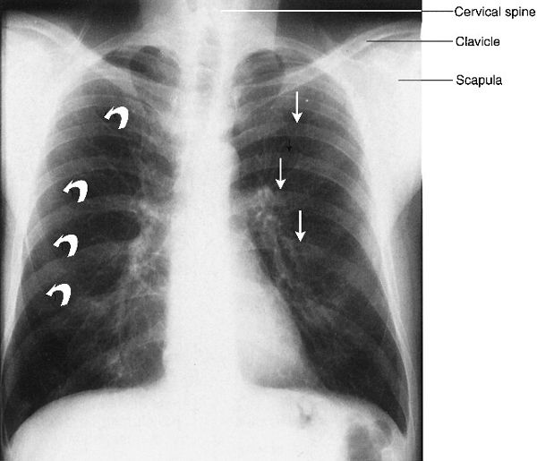
FIGURE 2.11 Chest PA radiograph. Normal. The posterior ribs (straight arrows) are horizontal and anterior ribs (curved arrows) are angled caudad or inferiorly. All of these osseous structures must be included in your checklist as well as the shoulder girdles and cervical and dorsal spine areas.
Finally, again observe the contours of the diaphragms and the posterior costophrenic angles (or sulci), which dive deep to overlie the upper lumbar spine. The right hemidiaphragm should be slightly lower and more magnified than the left. This is important in determining the location of a small pleural effusion, which may not be apparent on the frontal film. Note that the right hemidiaphragm can be seen in its entirety, because air in the right lower lobe abuts the soft tissue density hemidiaphragm allowing a sharp interface to be formed. On the left side, only the apex and posterior portions of the hemidiaphragm are visualized. The anterior aspect of the left diaphragm, which lies adjacent to the heart and pericardial fat, becomes largely obscured due to similar densities of these structures (Fig. 2.15). This observation is an important radiological concept; whenever two abutting objects of similar density are in direct juxtaposition, the interface or borders between these objects is lost. This phenomenon is known as the silhouette sign and is a powerful and important radiological observation useful for detecting pathology. Because most pulmonary pathology is water or soft tissue in density, the silhouette sign facilitates the detection and location of such pathology. For example, disease processes within the left lower lobe such as pneumonia or atelectasis will obscure the border of the left hemidiaphragm (see Figs. 2.49A, B). Similarly, since the right middle lobe is located immediately adjacent to the right cardiac border, any right middle lobe process should obliterate the right cardiac border on the frontal radiograph. The same observation also holds true for disease processes within the lingular segments of the left upper lobe, which will obscure or silhouette out the left heart border.

FIGURE 2.12 Chest lateral radiograph. Normal. The radiograph is positioned on the viewbox with the patient facing to either your left or right. Note that the cardiac silhouette is an anterior structure and makes an excellent starting point for your evaluation. The faint vertical water density line (straight arrows) represents the inferior vena cava.
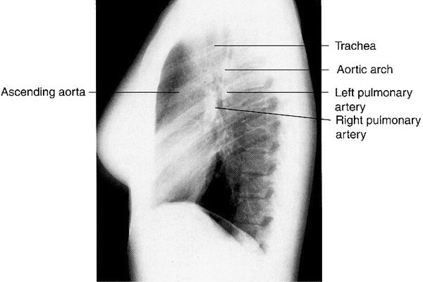
FIGURE 2.13 Chest lateral radiograph. Normal. Note that the oval-shaped right pulmonary artery lies anterior and inferior relative to the left pulmonary artery. The left pulmonary artery crosses cephalad over the left main stem bronchus and it lies inferior to the aortic arch.

FIGURE 2.14 A: Chest lateral radiograph. Normal. The anterior and posterior osseous structures should always be routinely viewed. The spine appears darker or more dense as you proceed caudally due to attenuation by the shoulders. B: Illustration of the spatial relationships of the pulmonary lobes on the lateral view. Note that the right middle lobe and the lingular segments of the left upper lobe (curved arrows) project over the heart (straight arrow). The lower lobes are primarily posterior structures. The major fissures extend up to approximately the T4 level.
ANTEROPOSTERIOR LORDOTIC CHEST
There are occasions when routine films show an equivocal or ill-defined lesion within the upper lobes that needs further characterization. In these situations, a special lordotic radiograph can be obtained which is essentially a frontal AP film, with the patient leaning backward (Fig. 2.16). This projection displaces the clavicles above the thoracic inlet and enables better visual evaluation of the lung apices. This specialized view is usually only indicated when upper lobe pathology is suspected on routine chest films.
Placing a patient on his/her side and obtaining an AP film by shooting across the x-ray table or bed produces what is known as a decubitus chest film. These examinations are primarily reserved when standard films suggest pleural disease (fluid or air) that needs to be confirmed and quantified. Decubitus films are capable of demonstrating very small pleural air or fluid collections and can be done portably on bedridden patients (Figs. 2.17A, B).
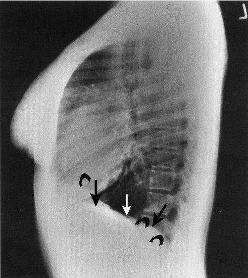
FIGURE 2.15 Chest lateral radiograph. Normal. Note that the left hemidiaphragm (straight arrows) is not visible anteriorly where it abuts the water density heart. On the other hand, the entire right hemidiaphragm (curved arrows) is visible. This is an excellent example of the silhouette sign.
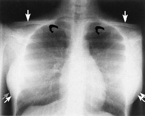
FIGURE 2.16 Chest AP lordotic radiograph. Normal. This view is obtained with the patient leaning backward a few degrees. Note how the clavicles (straight arrows) project cephalad to the apices of both lungs allowing an improved view of the upper lobes (curved arrows). The scapulae project somewhat lower than on the standard AP or PA radiograph. The breasts are indicated by the double straight arrows.
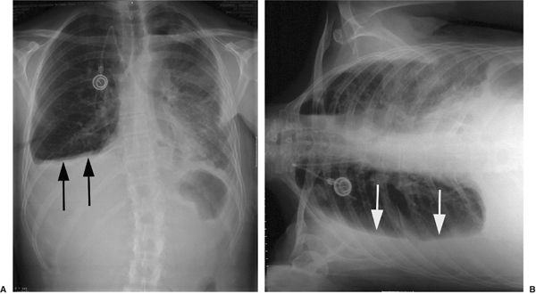
FIGURE 2.17 A: PA chest film shows a right pleural effusion (arrows). B: Right lateral decubitus film of same patient in figure A shows that the effusion is free-flowing and provides better quantitation of the size of the effusion.
NORMAL THORACIC SECTIONAL ANATOMY
The images in Figs. 2.18 through 2.26 demonstrate thoracic sectional anatomy by CT and magnetic resonance (MR).
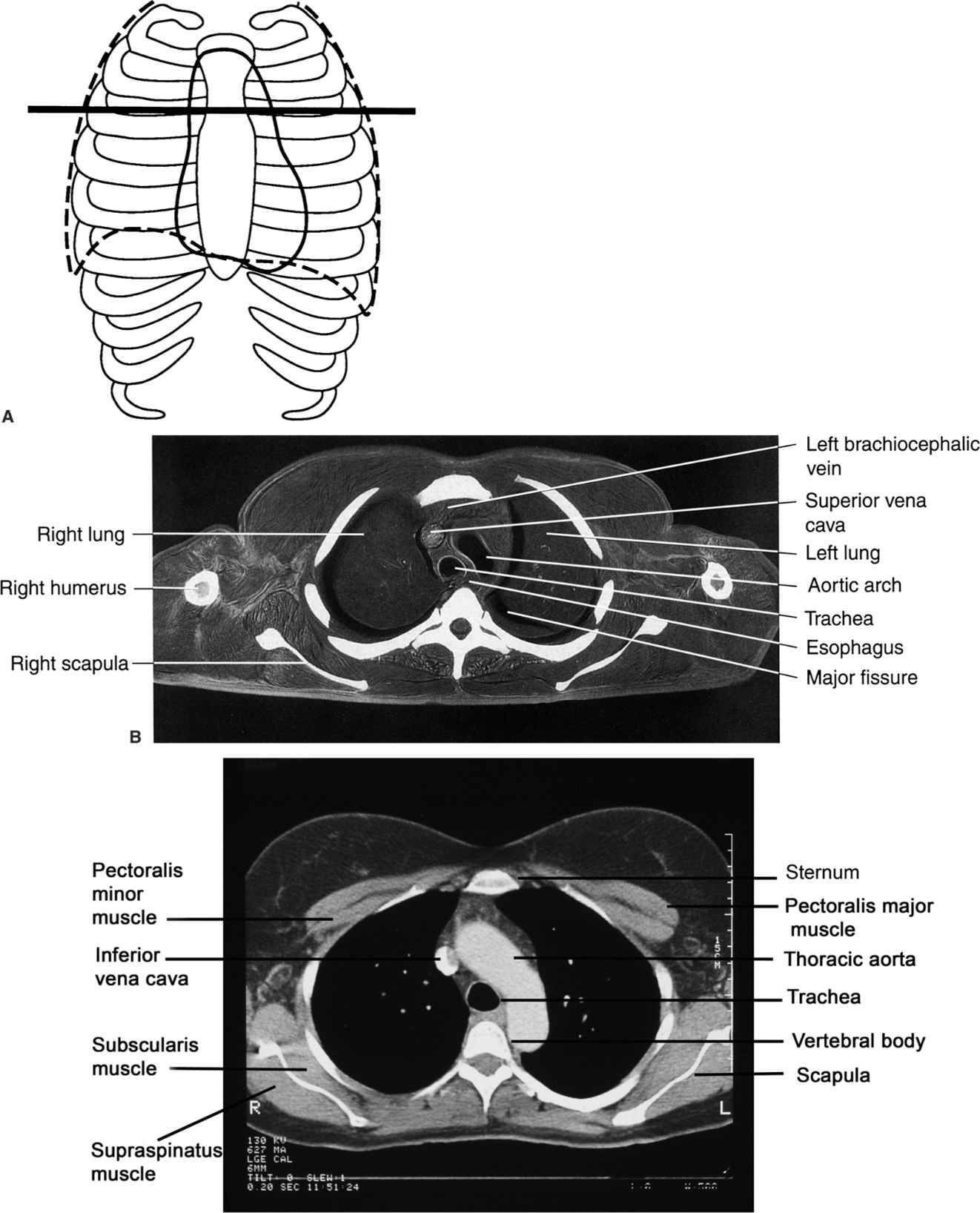
FIGURE 2.18 A: Approximate axial anatomic level through the aortic arch for B, C. B: Axial cadaver radiograph of the sectioned chest at the aortic arch level. Normal. A frozen cadaver was sectioned and then radiographed. C: Normal chest CT image at the aortic arch level with mediastinal windows (C).
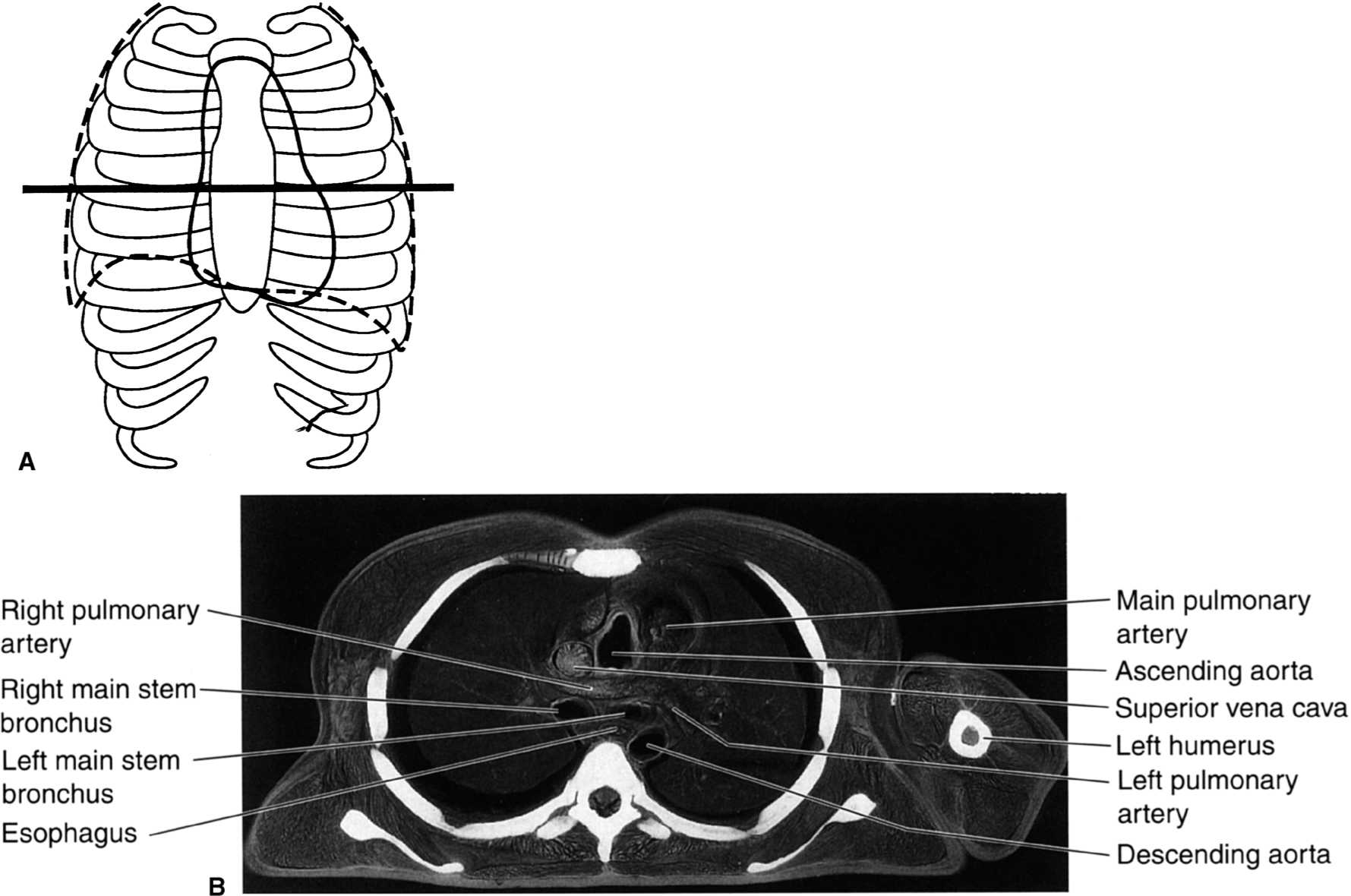
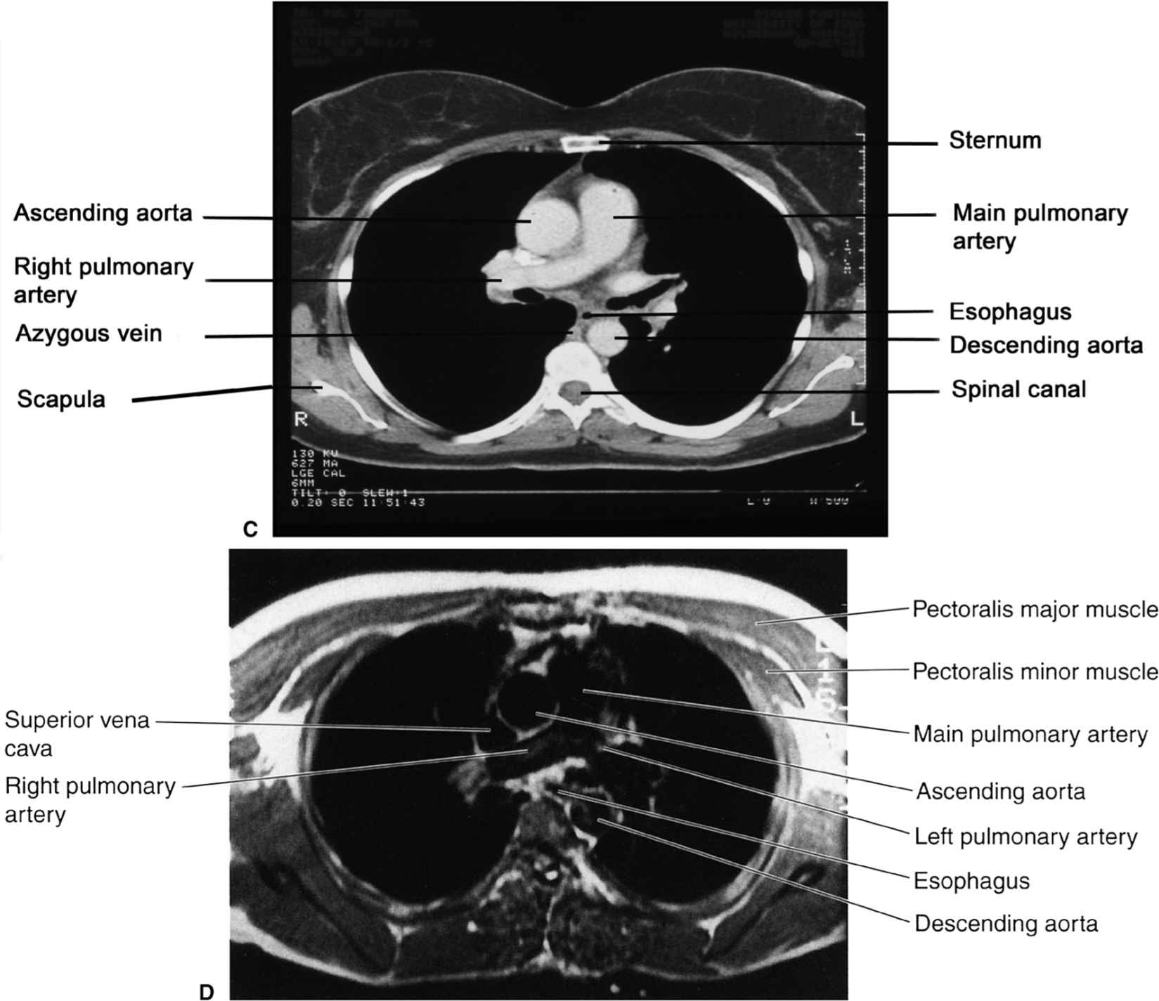
FIGURE 2.19 A: Approximate axial anatomic level through the pulmonary arteries for B–D. B: Axial cadaver radiograph of the sectioned chest at the level of the pulmonary arteries. Normal. C: Chest axial CT images at the level of the pulmonary arteries in mediastinal (C) windows (D). Normal. D: Chest axial MR image at the level of the pulmonary arteries. Normal.
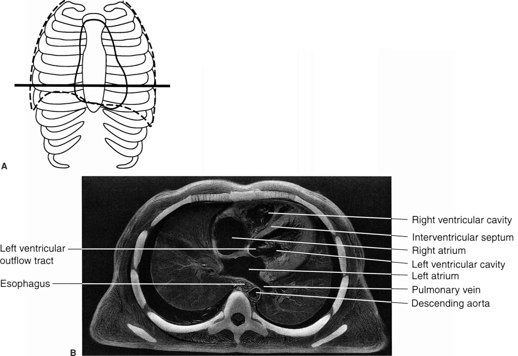
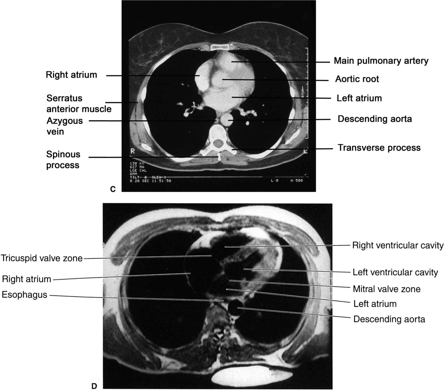
FIGURE 2.20 A: Approximate axial anatomic level through the right and left atria for B–D. B: Axial cadaver radiograph of the sectioned chest at the level of the right and left atria. Normal. C: Chest axial CT images at the level of the atria in mediastinal (C) windows. Normal. D: Chest axial MR image at the level of the atria. Normal.
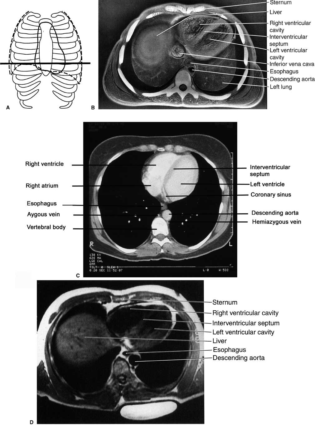
FIGURE 2.21 A: Approximate axial anatomic level through the right and left ventricles for B–D. B: Axial cadaver radiograph of the sectioned chest at the level of the ventricles. Normal. C: Chest axial CT image through using a mediastinal window (C) Normal. D: Chest axial MR image at the level of the ventricles. Normal.
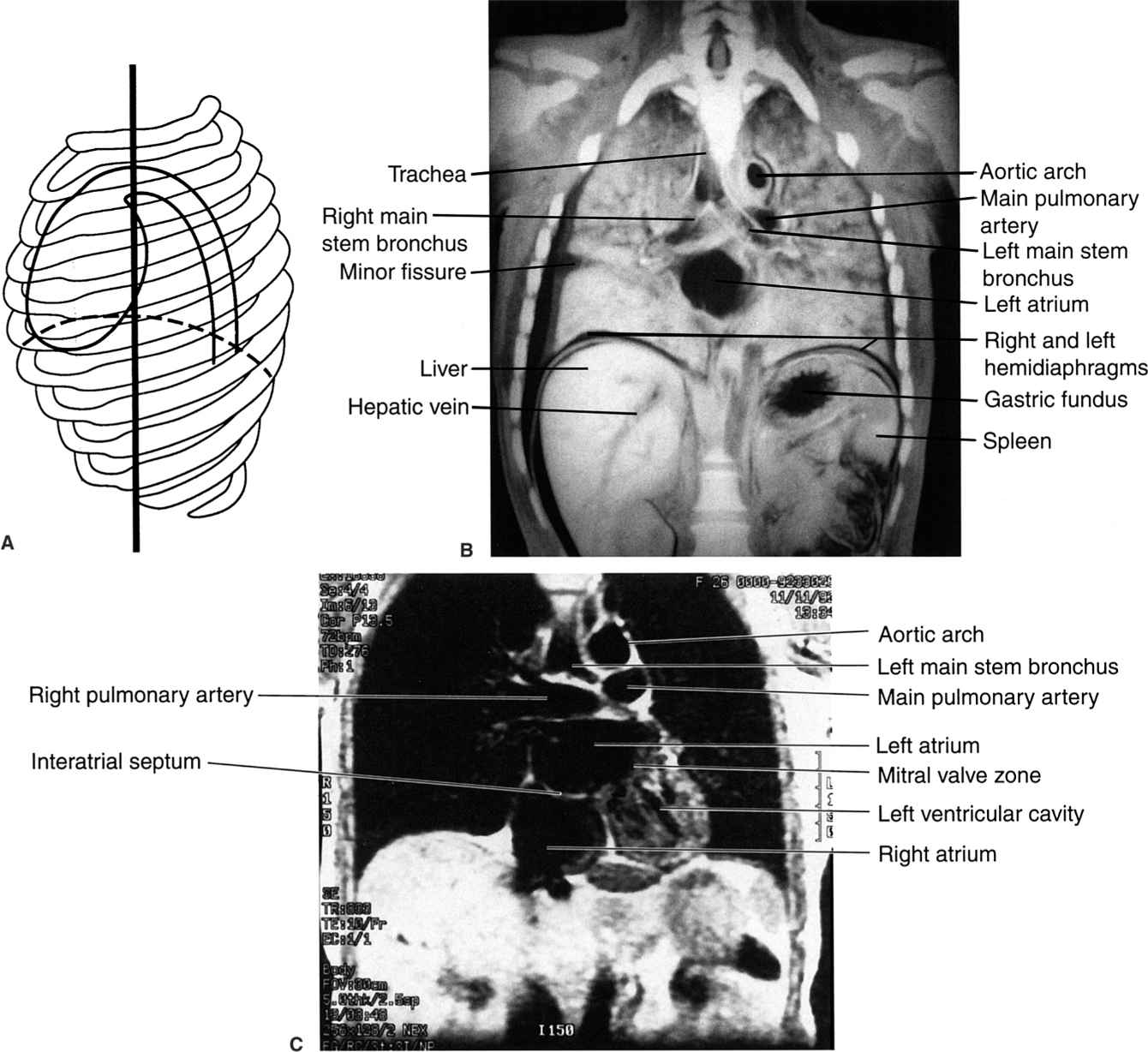
FIGURE 2.22 A: Illustration of the approximate coronal anatomic level through the left atrium for B and C. B: Coronal cadaver radiograph of the sectioned chest through the level of the left atrium. Normal. C: Chest coronal MR image through the right and left atria. Normal.
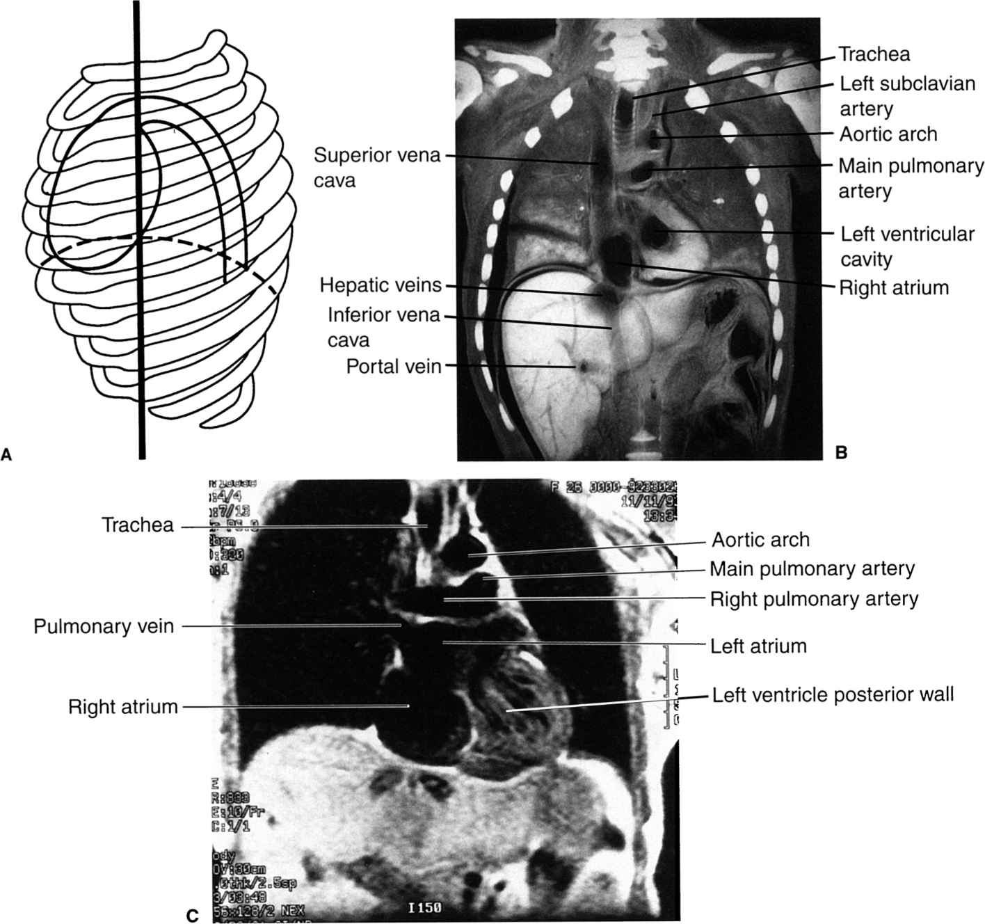
FIGURE 2.23 A: Approximate coronal anatomic level through the right atrium and left ventricle for B and C. B: Coronal cadaver radiograph of the sectioned chest through the level of the right atrium and left ventricle. Normal. C: Chest coronal MR image through the atria and left ventricle. Normal.
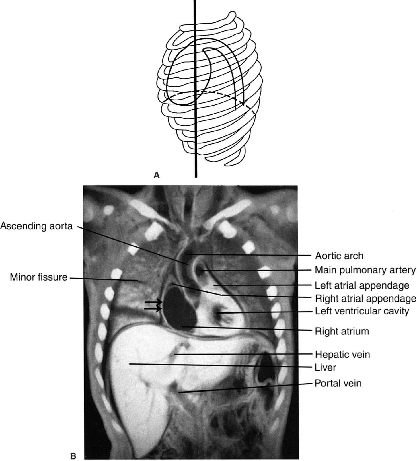

FIGURE 2.24 A: Illustration of the approximate coronal anatomic level through the left ventricle and the ascending aorta for B and C. B: Coronal cadaver radiograph of the sectioned chest through the left ventricle and the ascending aorta. Normal. Note that the convex right cardiac border is due to the right atrium (straight arrows). C: Chest coronal MR image through the left ventricle and the ascending aorta. Normal.
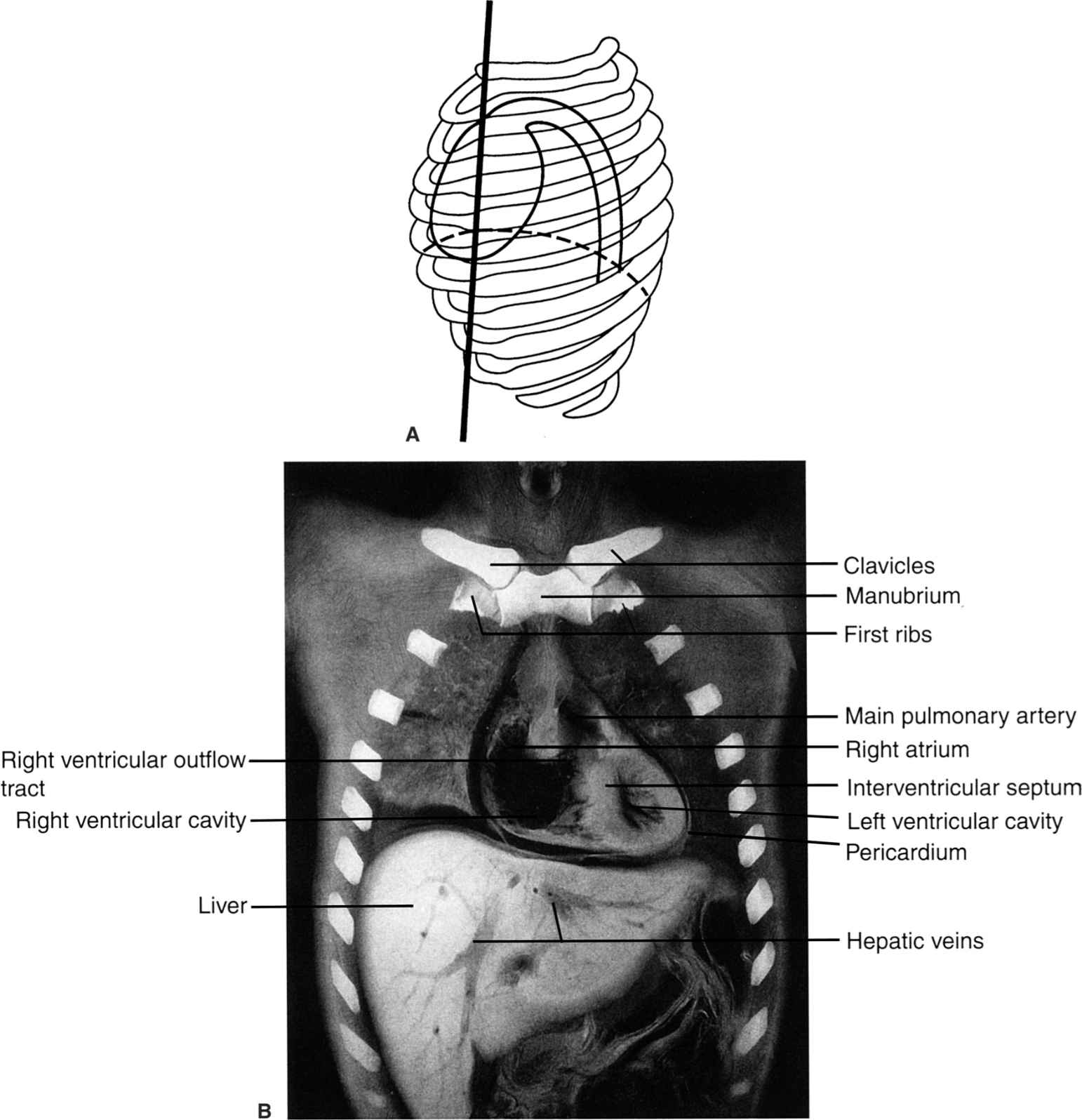
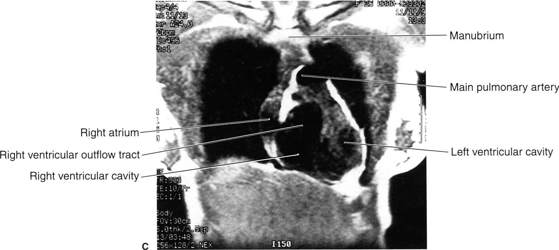
FIGURE 2.25 A: Illustration of the approximate coronal anatomic level through the ventricles for B and C. B: Coronal cadaver radiograph of the sectioned chest through the ventricles. Normal. C: Chest coronal MR image through the ventricles. Normal.

FIGURE 2.26 A: Illustration of the approximate sagittal anatomic level for B. B: Sagittal cadaver radiograph of the sectioned chest through the right ventricular outflow tract and the right ventricle. Normal.
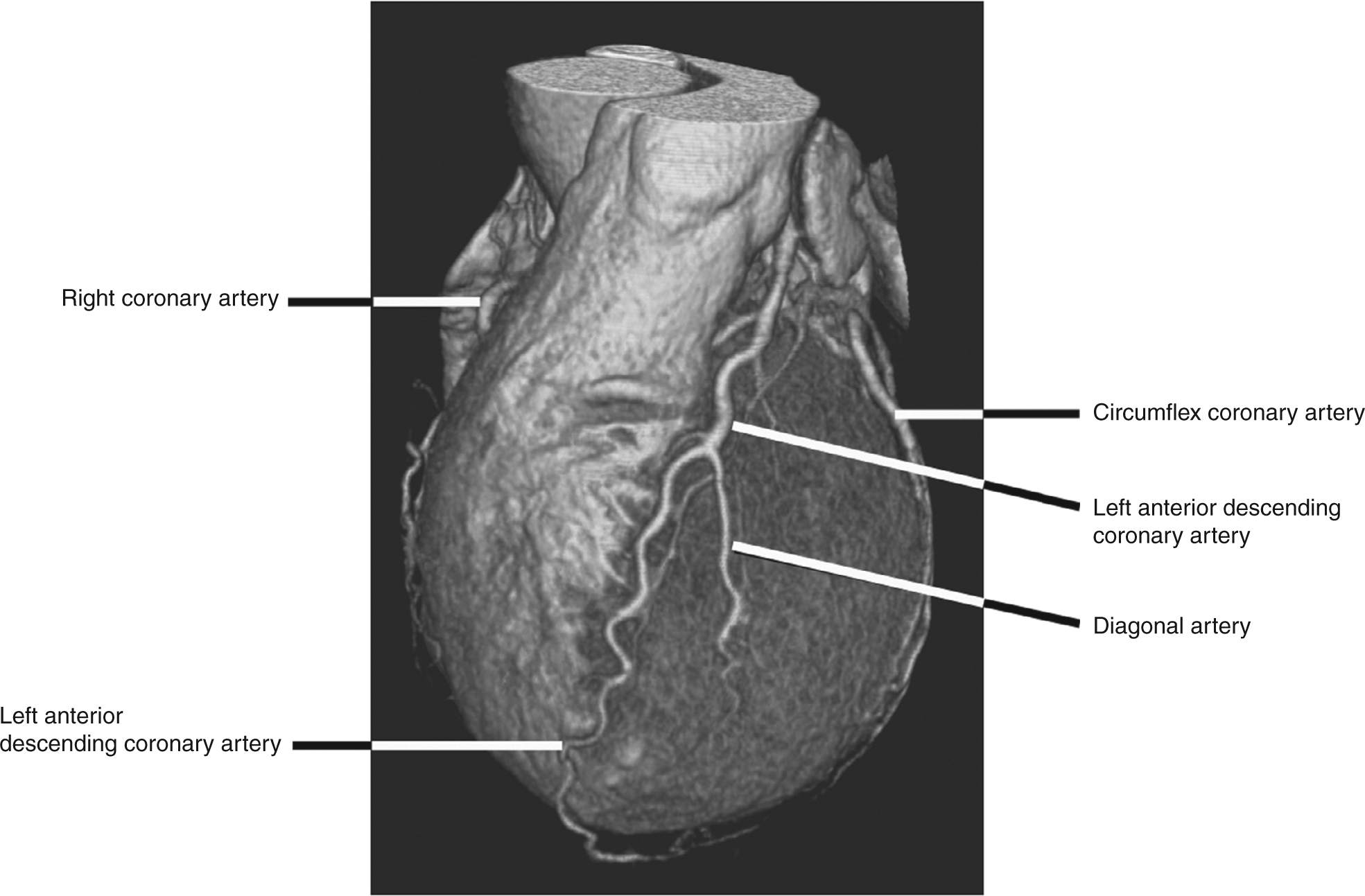
FIGURE 2.27 Shaded surface display CT reconstructed image of the heart from a CT coronary angiogram illustrates the coronary arteries running along the left side of the heart. The left anterior descending coronary artery supplies most of the left ventricle while the circumflex artery runs in the left atrio-ventricular groove. A portion of the right coronary artery is visible along the left side of the image.
CARDIAC COMPUTED TOMOGRAPHY IMAGING
In general, computed tomography (CT) is the preferred modality for chest and pulmonary imaging primarily due to faster image acquisition, less susceptibility to artifacts than MR, and greater scanner availability. Spiral CT technology makes it possible to acquire a complete data set of the entire chest easily within one breath hold. Using standard chest CT protocols, scanners can produce contiguous 3-mm images of the entire chest usually within 15 seconds. The latest generation multislice spiral CT scanners, which possess subsecond imaging acquisition speeds are also capable of producing dynamic imaging of the beating heart with excellent spatial and temporal resolution. Using this technology, noninvasive coronary CT arteriography can be readily performed on patients with suspected coronary artery disease, negating the need in many cases for cardiac catheterization (Fig. 2.27). One significant limitation of MR for chest imaging is the lack of sufficient resolution of lung detail due to the low proton composition of lung tissue as well as potential problems of image degradation due to excessive respiratory motion.
Congenital anomalies can involve the sternum, clavicles, bronchi, lungs, heart and great vessels, and diaphragms. Anomalies which have obvious clinical manifestations are usually detected in infancy or early childhood. Other anomalies especially those involving only the skeletal system may not be apparent until revealed by radiographs obtained for unrelated reasons. While numerous chest anomalies exist, only a few will be illustrated.
Pectus excavatum, or funnel chest (Fig. 2.28), is a common and usually asymptomatic abnormality of the chest wall that can be associated with other congenital abnormalities such as Marfan’s syndrome, scoliosis, and Poland’s syndrome (1). Therapy which consists of surgical repair is usually performed in patients with chest pain or for cosmetic reasons. Pectus carinatum, or pigeon breast (Fig. 2.29), can be either a congenital or an acquired abnormality wherein the sternum bows anteriorly. These patients are usually asymptomatic, and corrective therapy is usually not indicated (1). The acquired form of pectus carinatum may occur in patients with untreated congenital heart disease.
Another skeletal abnormality is congenital absence of the clavicles (Fig. 2.30), which is associated with cleidocranial dysostosis, a syndrome manifested by delayed or incomplete calvarial ossification, hypoplasia or aplasia of the clavicles, and many other associated osseous abnormalities (2).
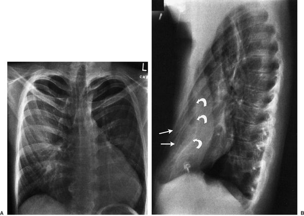
FIGURE 2.28 Chest PA (A) and lateral (B) radiographs. Pectus excavatum. Note that on the PA view the cardiac silhouette is rotated and displaced to the patient’s left, and the left cardiac border is straight simulating mitral valve disease. There is mild deformity of the ribs bilaterally on the PA view. The extent of the defect is best appreciated on the lateral view where the anterior ribs (straight arrows) project anterior to the sternum (curved arrows).
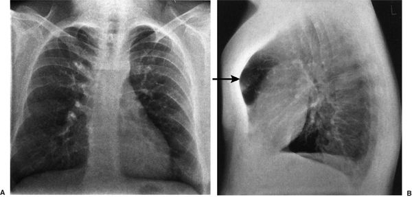
FIGURE 2.29 Chest PA (A) and lateral (B) radiographs. Pectus carinatum. The PA view is essentially normal with mild dorsal spine scoliosis. The exaggerated anterior bowing of the sternum (straight arrow) is best appreciated on the lateral view.
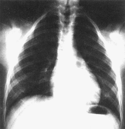
FIGURE 2.30 Chest AP radiograph. Cleidocranial dysostosis with bilateral absence of the clavicles. This was a routine chest radiograph in an asymptomatic 20-year-old woman.
Superior migration of the azygos vein up over the superior recess of the right upper lobe creates a mock vertical fissure-like opacity (Fig. 2.31, see Fig. 2.37B) which is created by indentation of both the visceral and the parietal pleural surfaces along the arc-like course of the vein as it courses inferiorly to insert normally into the superior vena cava. This azygos fissure, which is only visualized on PA radiographs as a thin curvilinear line, is a common normal variant and portends no clinical significance.
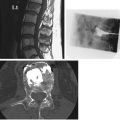
The most common thoracic aortic anomaly is a right aortic arch with a left descending thoracic aorta. In these cases, the transverse portion of the thoracic aorta crosses from right to left posterior to the esophagus to establish the descending thoracic aorta which runs in a left paraspinal location (Fig. 2.32). On the PA radiograph, the right-sided arch often appears more cephalad than a normal left-sided arch. There are five types of right aortic arch, and the classification is based on the arrangement of the arch vessels (3). Right-sided aortic arches can also be found in tetralogy of Fallot and other severe congenital heart anomalies.
Another vascular anomaly is coarctation of the aorta. Anatomically, this anomaly consists of a focal narrowing or stricture of the descending portion of the thoracic aorta. The degree of coarctation is variable, and the signs, symptoms, and physical findings vary with the location and degree of stenosis. Disparate blood pressures between the upper and lower extremities suggest the diagnosis.
The upper extremities blood pressures may be unequal if the location of the stenosis is proximal to the origin of left subclavian artery. Additional features include a systolic murmur, cardiac enlargement, and pre- and poststenotic aortic dilatation depending on the location and severity of the stenosis. Often, the site of stenosis can be identified on routine chest radiographs (Fig. 2.33). Rib notching can occur along the inferior aspect of the ribs reflecting augmented collateral blood flow through dilated intercostal arteries in an attempt to bypass the stenotic segment (Fig. 2.33).
CONFUSING EXTRATHORACIC CONDITIONS
On occasion there are objects outside the thorax that can be confused with intrathoracic pathology (Figs. 2.34 to 2.36). It is important to keep such possibilities in mind at all times.
FOREIGN BODIES, LINES, AND TUBES
Another pitfall on chest radiographs that must be kept in mind is the presence of intrathoracic foreign bodies (Fig. 2.37). Some foreign bodies such as lines and tubes are intentionally placed within the thorax. It is very important to recognize the typical appearances of these commonly used lines and tubes, especially when caring for patients in acute care areas. The normal and some abnormal locations of some of these lines and tubes are demonstrated in Fig. 2.38.
It is important to recognize some common radiographic findings that may be present on postoperative chest images (Fig. 2.39).
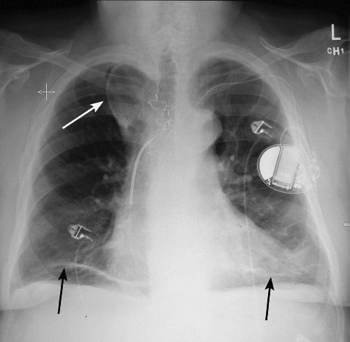
FIGURE 2.31 Chest PA radiograph. Azygos lobe. The azygos lobe is outlined with a straight white arrow. Also note the areas of discoid atelectasis in the lower lobes (black arrows) on the chest film.
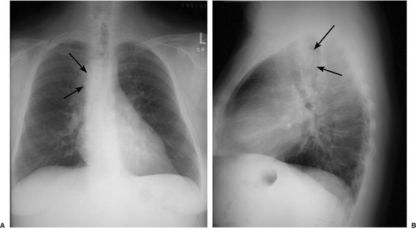
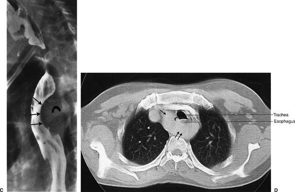
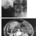
FIGURE 2.32 Chest PA (A) and lateral (B) radiographs, barium swallow (C), and chest CT (D). Right-sided aortic arch and left descending thoracic aorta. This 42-year-old male smoker was suspected of having cancer of the lung. A neoplastic mass was suspected on the PA radiograph (A) but this proved to be an ill-defined aortic knob to the right of the midline (straight arrows). The right aortic arch is indenting the right side of the trachea). The right-sided aortic arch indents the posterior aspect of the trachea (straight arrows) on the lateral radiograph (B). Barium swallow (C) confirms a significant indentation on the posterior aspect of the barium-filled esophagus (straight arrows) secondary to the crossing aortic arch (curved arrow). The diagnosis is confirmed on chest CT (D) that shows the right-sided aorta (single straight arrow) passing posterior to the esophagus and trachea (double straight arrows) to reach the left side of the thorax. Again, note the indentation on the right side of the trachea (curved arrow) secondary to the right-sided aortic arch.

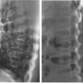
FIGURE 2.33 Chest PA (A) and lateral (B) radiographs. Coarctation of the aorta. The classical PA radiographic appearance is an indentation (arrow) involving the lateral aspect of the proximal descending aorta (A) and a posterior indentation (arrow) involving the posterior aspect of the proximal descending aorta on the lateral radiograph (B). These indentations represent the site of stenosis or coarctation in the proximal descending aorta. Rib notching (black/white arrows Figure A) is also evident along the inferior margins of several ribs. This notching represents collateral blood flow through dilated intercostal arteries. Figure C is an aortic angiogram which shows the classic narrowing of the upper portion of the descending thoracic aorta characteristic of coarctation (arrow).

FIGURE 2.34 PA chest radiograph. Hair artifacts (straight arrows) projecting over the upper lobes. Hair, hair braids, ponytails, and ribbons can project over the upper lobes and should not be confused with a pathologic process.
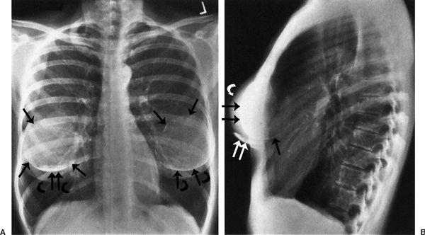
FIGURE 2.35 Chest PA (A) and lateral (B) radiographs. Bilateral breast augmentations or implants. The breast implants (straight arrows) are partially opaque, and the native breasts are indicated by the curved arrows. Note the benign postoperative calcification on both the PA and lateral views (double straight white arrows) in the inferior aspect of the right breast. The hyperinflated lungs are probably within limits.
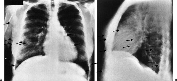
FIGURE 2.36 Chest PA (A) and lateral (B) radiographs. Multiple soft tissue nodules projecting over the thorax from neurofibromatosis. Multiple subcutaneous soft tissue nodules (arrows) project over the thorax and must not be mistaken for pulmonary nodules.
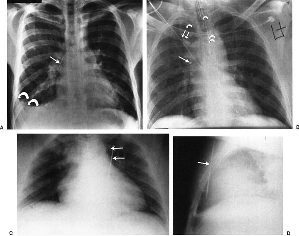
FIGURE 2.37 A: Chest PA. Aspirated straight pin (straight arrow) in the right intermediate bronchus. Note the right pleural effusion (curved arrows). It has been estimated that there must be at least 125 cc of pleural fluid before it is recognized on PA and AP views. B: Chest portable AP radiograph. Tooth fragment (straight arrow) in the right bronchial tree. The patient was involved in a motor vehicle accident, and a portion of a tooth was missing. The chest radiograph shows the tooth fragment projecting over the right upper bronchial tree. Note that the endotracheal tube (single curved arrow) lies to the patient’s right of the nasogastric tube (double curved arrows). An azygos lobe is present, and the double straight arrows indicate the position of the azygos vein that is more lateral and cephalad than normal. The azygos lobe (curved white arrow) is visible. C, D:Chest AP (C) and lateral (D) radiographs. Darning needle lodged in the right ventricle. The child of this young mother accidentally stabbed her with a darning needle. Note that the needle (straight arrows) projects over the right ventricle region in both views. The needle was successfully removed at thoracotomy.

FIGURE 2.38 A: Chest AP radiograph. Normal tube and line positions. The tip of the central line via a right jugular vein approach projects over the superior vena cava. The curved arrow points to a monitoring electrode that lies on the skin on the patient’s left shoulder. B: Chest AP radiograph. Right jugular central line inadvertently passed into the right subclavian vein (single straight arrow). Bilateral breast implants are present (single curved arrows). A monitoring electrode (double straight arrows) and a nasogastric tube (double curved arrows) are also present. C: Chest AP radiograph. The Hickman line (straight arrows) with an infusaport is directed cephalad up into the right jugular vein rather than caudad toward the superior vena cava. The tip of the line is beyond the edge of the radiograph. D: Chest AP radiograph. Endotracheal tube (arrow) inadvertently placed in right intermediate bronchus. External monitoring electrodes are present (curved arrows).
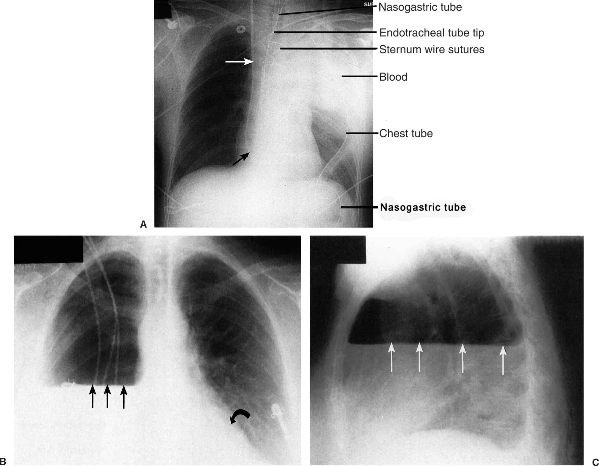
FIGURE 2.39 A: Chest AP supine radiograph. Postoperative left hemothorax. The white homogeneous density in the region of the left upper lobe represents active bleeding in the thorax 2 hours following coronary artery bypass grafting. The patient was reoperated to evacuate the blood and control the bleeding. The straight arrows indicate a right jugular Swan-Ganz catheter. B, C:Chest AP (B) and lateral (C) radiographs. Right pneumonectomy. The straight arrows indicate the presence of an air–fluid level in the chest cavity that is a common finding following pneumonectomy. Gradually over a period of days the right chest cavity will fill with fluid. Left lower lobe atelectasis is manifested by the retrocardiac double density (curved arrow). Left lower lobe atelectasis is common following thoracic surgery. There is obliteration of the right hemidiaphragm (silhouette sign) by the right pleural fluid.
An important chest problem that can have significant clinical ramifications is pneumothorax (air accumulation within the pleural space). Pneumothorax most often is secondary to trauma or due to iatrogenic causes. A list of potential etiologies is shown in Table 2.1. Spontaneous pneumothorax most commonly occurs in young, thin asthenic male adults but can involve female patients as well. These patients typically present with a sudden onset of unilateral chest pain that can be accompanied by varying degrees of shortness of breath. The etiology of spontaneous pneumothoraces is likely due to rupture of small lung cysts. As is true for all pleural air collections, treatment depends on size of the pneumothorax and whether coexisting clinical symptoms such as dyspnea exist.
The definitive radiographic diagnosis of pneumothorax is made by identifying the visceral pleura edge (Fig. 2.40A). Figure 2.40 illustrates three cases of pneumothorax of varying sizes. Additional findings include an abnormally hyperlucent lung or hemithorax and loss of normal lung markings on the affected side. Upright or decubitus films are the most sensitive methods to document the presence of pleural air. Recumbent portable films on the other hand are notoriously insensitive for demonstrating even large pleural air collections, largely because the air resides immediately ventral to the lung and in essence becomes invisible. A tension pneumothorax is present when the air component within the pleural space is sufficiently large to produce mass effect upon the mediastinal structures and ipsilateral diaphragm. In these cases, the mass effect on the heart and great vessels can produce acute cardiovascular collapse due to diminished cardiac output. Acute respiratory problems are also likely to coexist due to compression of lung tissue and mass effect upon the diaphragm (see Fig. 2.40C). A tension pneumothorax is a surgical emergency requiring immediate placement of chest tube to decompress the pleural space.

Related posts:
Stay updated, free articles. Join our Telegram channel

Full access? Get Clinical Tree


