16 Advanced Techniques in Musculoskeletal MRI Imaging of the musculoskeletal system typically begins with radiographs, CT, or conventional MRI. Several advanced MRI techniques have proven useful for the evaluation of subtle and complex pathology, such as early manifestations of disease, preoperative planning, and postoperative analysis. In addition, advanced MRI techniques may be helpful in narrowing a differential diagnosis, addressing a specific clinical question, or evaluating a finding detected on another imaging study. This chapter addresses techniques in musculoskeletal MRI that are increasingly used to assist clinical problem-solving. Although conventional MRI often detects complex joint pathology with high sensitivity, MR arthrography is useful for the depiction of intraarticular structures that may be subtle or incompletely seen on a routine study. MR arthrography is especially useful for postoperative patients and for the evaluation of suspected ligamentous, cartilaginous, or labral injury. Arthrography relies on distention or enhancement of the joint with contrast medium to separate or enhance structures effectively, thereby defining joint pathology with increased clarity.1 Direct and indirect methods of MR arthrography are commonly used. This technique is a sterile, minimally invasive procedure in which dilute gadolinium or saline is directly injected into the joint of interest under fluoroscopic guidance, followed by immediate MRI. Although gadolinium-based contrast agents have not been approved by the FDA for intraarticular injection, they are commonly used clinically under the doctrine of the practice of medicine. The optimal gadolinium concentration for adequate signal intensity is 2 mmol/L, which is achieved by dilution with normal saline; this solution then is combined with iodinated contrast material and 1% lidocaine before joint injection.2 The total amount of dilute gadolinium injected varies by joint and patient size (Table 16.1).3 To prevent suboptimal joint distention and additional dilution of gadolinium, imaging of the joint should be performed no later than 30 minutes after injection. Although conventional MRI is often useful, direct arthrography offers improved sensitivity for the detection of many OCDs and other ligamentous, articular, and synovial defects. In the shoulder, partial-thickness rotator cuff tears are seen more clearly when there is filling of focal cuff defects with gadolinium solution. Anatomic variants of the shoulder that may otherwise be mistaken for pathology are often better defined with arthrography. Labral tears of the glenoid and hip are sometimes difficult to differentiate from normal anatomic structures (Fig. 16.1) and may be more clearly seen when contrast extends into the labral substance (Fig. 16.2). Recurrent or residual meniscal tears in the knee may be seen more clearly with arthrography because a normal postoperative meniscus has an abnormal configuration that may exhibit abnormal signal.4 Arthrography offers additional detail in the evaluation of injury to the lateral ligaments of the ankle, especially the calcaneofibular ligament. Partial under-surface tears of the UCL and RCL in the elbow may not be clearly seen without arthrography (Fig. 16.3). TFCC and intrinsic intercarpal ligamentous abnormalities may be more conspicuous with MR arthrography. Direct arthrography is particularly useful for the detection of intraarticular loose bodies and OCDs. This technique requires the uptake of intravenous gadolinium by highly vascular synovial membranes, which diffuses into existing joint fluid, creating the “arthrographic effect.” The main benefit of this method is that intraarticular structures may be visualized without percutaneous access to a joint, which may be traumatic, time-consuming, or logistically difficult. Once gadolinium (0.1 mmol/kg) is injected intravenously, the patient must gently exercise the joint in question for approximately 10 to 15 minutes to increase vascular perfusion and joint pressure, improving the gadolinium’s diffusion. Imaging is performed 5 to 30 minutes after contrast injection, depending on the joint.
 MR Arthrography
Direct Arthrography
Indirect Arthrography
Joint | Minimum to Maximum Volume to Inject (mL) |
Shoulder | 10 to 20 |
Elbow | 9 to 10 |
Wrist | 3 to 6 |
Hip | 8 to 20 |
Knee | 20 to 40 |
Ankle | 8 to 15 |
Source: Adapted from Sahin G, Demirtas M. An overview of MR arthrography with emphasis on the current technique and applicational hints and tips. Eur J Radiol 2006;58:416–430. Adapted by permission.
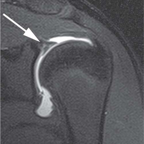
Fig. 16.1 This coronal oblique fat-suppressed T1-weighted image of a SLAP lesion in the left shoulder was obtained after the intraarticular injection of a dilute gadolinium solution posterior to the biceps attachment to the glenoid. This direct MR arthrogram shows an irregular collection of contrast material (arrow) extending into the superior labrum with partial detachment.
The success of indirect arthrography is limited for noninflamed joints because noninflamed synovium does not en hance well. Additionally, indirect enhancement may not be helpful for large joints that require a greater amount of distention or for patients with tense joint effusions. Indirect arthrography is therefore best suited for smaller joints. Subtle cartilage defects, loose bodies, and hyperemic tendons and sheaths in the wrist, elbow, ankle, and knee may also be seen more clearly with contrast compared with conventional MRI techniques (Fig. 16.4). For example, recurrent tears in a postoperative knee may exhibit synovial hyperemia with joint fluid infiltrating a tear. Unfortunately, many normal and postoperative structures enhance with gadolinium, so enhancement does not necessarily reflect an abnormality. Indirect arthrography offers a better depiction of extraarticular osseous and soft-tissue abnormalities than does direct arthrography.5
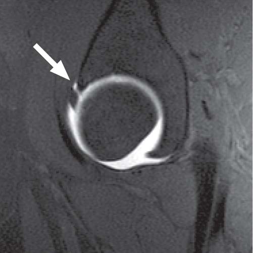
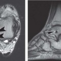
Fig. 16.2 This sagittal fat-suppressed T1-weighted image of the hip obtained after the intraarticular injection of a dilute gadolinium solution (direct MR arthrography) depicts contrast material through the anterior labral substance (arrow), reflecting a tear. Overall, the labrum maintains its triangular shape.
 Magnets and Imaging Equipment
3.0-T Magnets
High field strength MRI systems are becoming widely available in the clinical setting, typically with magnetic field strengths of 3.0 T. The higher intrinsic signal-to-noise ratio of high field strength MRI can be used to improve imaging speed or resolution, but there are changes in relaxation time at 3.0 T and increased artifacts to consider. Nevertheless, 3.0-T MRI offers the opportunity to explore physiologic imaging of joints and anatomy with greater definition.
Intrinsic signal-to-noise ratio is a function of the strength of the magnetic field, the volume of the tissue being imaged, and the RF coils used. All else being equal, 3.0 T should provide twice the intrinsic signal-to-noise ratio of 1.5 T, but this goal is not achieved clinically for several reasons. The FDA and manufacturers have mandated the use of power-monitoring systems for 3.0-T MRI systems because of the increased risk of RF burns. The more problematic sequences are FSE/turbo-spin and short TR SE (T1-weighted) sequences. Because motion, chemical shift, and susceptibility artifacts from metallic implants are increased at 3.0 T, postoperative imaging may be more problematic at higher field strengths.
Imaging speed is improved with higher field strength; therefore, it is theoretically possible to acquire images up to four times faster at 3.0 T than at 1.5 T while maintaining a comparable signal-to-noise ratio. In actuality, given the number of different considerations, it is typical to image only twice as fast with 3.0 T as with 1.5 T. Image acquisition time at 3.0 T may be optimized by minimizing the number of signal averages, increasing TR to account for longer T1 relaxation, use of a higher receiver bandwidth for non-FSE sequences, and use of small echo spacing for FSE/turbo-spin sequences. As mentioned above, the increase in signal-to-noise ratio at 3.0 T may be used to improve spatial resolution of images acquired by producing thinner and more numerous sections (Fig. 16.5).6–8
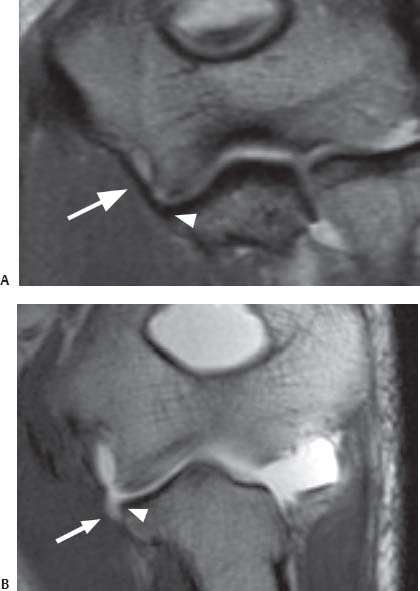
Fig. 16.3 Direct MR arthrography of the elbow. The T1-weighted coronal oblique (prescribed as a plane bisecting the humeral condyles) images obtained after the intraarticular injection of a dilute gadolinium solution show (A) the normal intact anterior bundle of the UCL (arrow), which is firmly affixed to the medial margin of the ulna (arrowhead), and (B) a partial articular surface tear as detachment (arrow) of the deep portion of the distal anterior bundle of the UCL from the medial margin of the ulna (arrowhead). Note that the contrast remains contained by the intact superficial layer of the UCL without extraarticular extravasation. This finding has been described as the “T” sign.
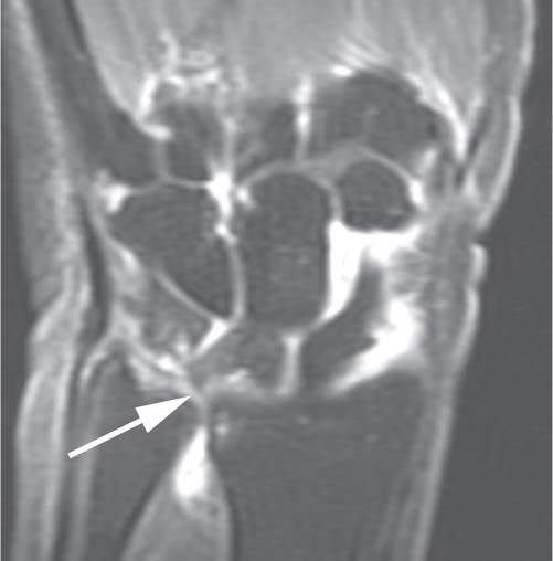
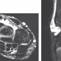
Fig. 16.4 This T1-weighted coronal oblique image of the wrist (indirect MR arthrography) shows multicompartment enhancement of the carpus and distal radioulnar joint. Findings of ulnocarpal abutment with a TFCC tear (arrow) are present.
Parallel Imaging
Parallel imaging is a relatively new class of techniques capable of substantially increasing the imaging speed of MRI. Parallel imaging involves using spatial information inherent in the elements of an RF coil array to allow a reduction in the number of time-consuming, phase-encoded steps required during a scan. Parallel imaging, therefore, imposes particular hardware requirements. Coil arrays must be used with separate preamplifiers and receivers for each individual element and with appropriate decoupling networks to decrease cross-talk between elements. Although these techniques may be used to some degree with existing coil arrays, many tailored array geometries have been designed specifically for parallel imaging. Parallel imaging techniques may be applied to any existing pulse sequence to reduce imaging time or increase spatial resolution. Resultant time savings can then be used to add modifications that would otherwise prohibitively lengthen a pulse sequence. Recent technical advances and increased availability have placed parallel imaging in widespread clinical use.
Increased imaging speeds do come with a well-defined signal-to-noise ratio penalty, which must be taken into account when developing protocols. Nevertheless, for sequences with sufficient baseline signal-to-noise ratio, parallel imaging can offer substantial benefits. There is great synergy with 3D volumetric acquisitions and high field strength MRI systems (higher signal-to-noise ratio), which facilitates a shift toward rapid, volumetric image acquisitions. Recently, major vendors of MRI scanners have implemented versions of parallel imaging in several commercial systems.9
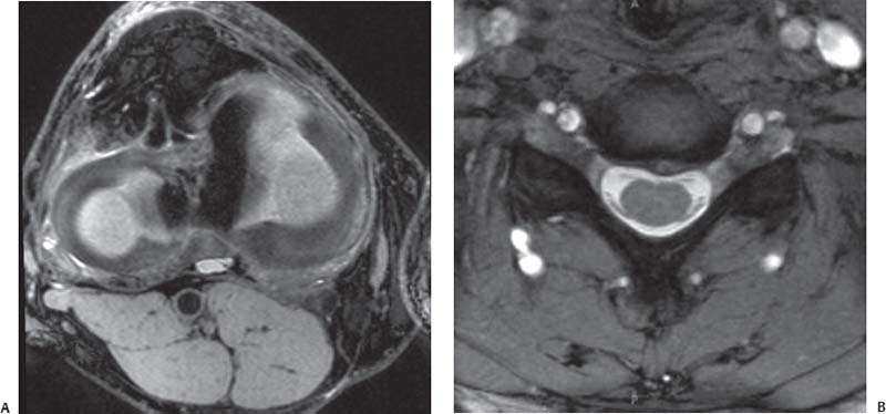
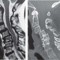
Fig. 16.5 3.0-T MRI. (A) An axial oblique multiplanar reconstruction image of the knee from a 3D isotropic image data set superbly shows the medial and lateral meniscal anatomy. (B) An axial T2*-weighted image (a T2-like image [bright fluid] created with a gradient-echo rather than an SE technique) at the C4-C5 level of the spine shows a high signal-to-noise ratio with high spatial resolution, providing excellent visualization of the ventral and dorsal roots in addition to a small central disc protrusion.
High-Resolution Imaging: MR Microscopy
MRI with microscopy coils offer much higher signal-to-noise ratio, higher contrast-to-noise ratio, and higher spatial resolution than does a conventional small surface coil. For example, resolution of conventional MRI has not permitted detailed evaluation of the entire TFCC, but primarily the triangular fibrocartilage proper (disc). However, the triangular ligament (upper and lower lamina), meniscus homologue, and ulnotriquetral ligament are clearly seen with microscopy coils. High-resolution MRI with a microscopy coil is a promising method with which to diagnose TFCC abnormalities and other ligamentous lesions (Fig. 16.6).
Microscopy coils are limited by inadequate depiction of deeper structures. This issue may be addressed by combined positioning with a larger surface coil or a flexible coil. In addition, the limited sensitivity of microscopy coils may make accurate coil setting over a targeted structure or lesion difficult. Superconducting coils have also been used for small joint imaging. Overall, it is likely that advanced coil development will lead to improved diagnostic performance of MRI because high-resolution imaging is paramount for the depiction of infrastructural features of the wrist and elbow when evaluating internal derangements.
Extremity Scanners
Low field strength open MR scanners and extremity scanners have been used for several years. Recently, a higher field 1.5-T extremity scanner (ORTHONE, ONI, Inc., Wilmington, MA) has become available clinically.10 This device can image the elbow, hand, wrist, knee, foot, and ankle, but it cannot acquire images of the shoulder, hip, or spine. Therefore, it is not considered as a stand-alone unit, but it may be useful as a supplement to a whole body scanner for a high-volume site with a backlog of musculoskeletal patients. Because there are fewer site requirements for this device than for a conventional high field strength system, an extremity scanner is often an economical imaging option. Additionally, extremity scanners may prove useful for imaging claustrophobic patients because the image quality of a 1.5-T extremity scanner is much better than that of a typical low field strength open MRI or a very low field strength extremity scanner. This type of device will likely fulfill a niche role, providing high-quality clinical images for designated body parts (Fig. 16.7).
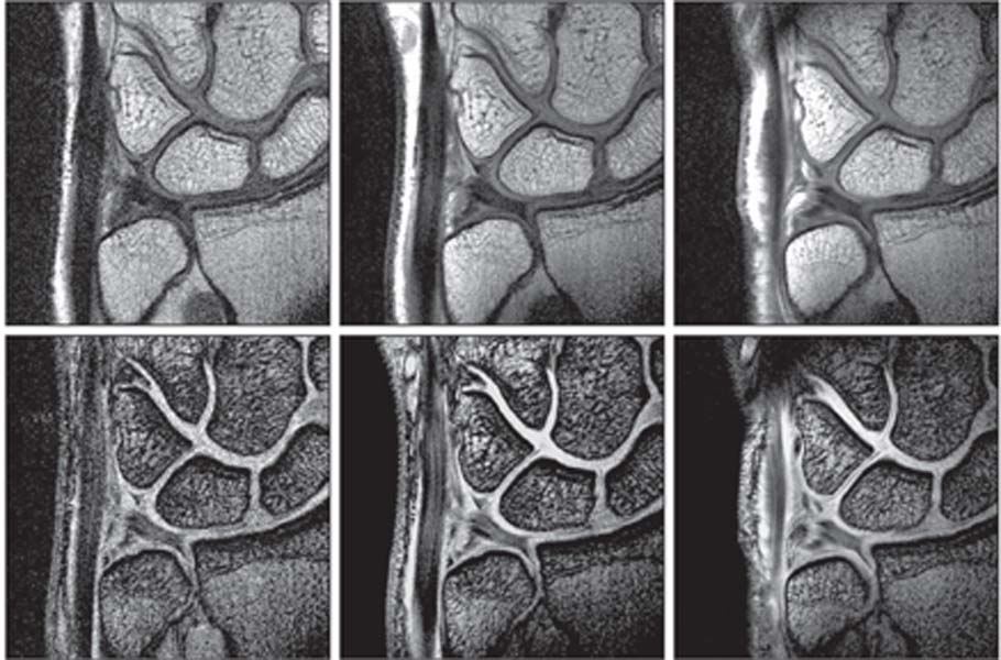
Fig. 16.6 These FSE proton-density images (top row) and coronal T2*-weighted images (T2-like images [bright fluid] created with a gradient-echo rather than a SE technique) (bottom row) of the TFCC were obtained with a 1.5-T MRI scanner and a conventional 80-mm diameter surface coil (left column), a 47-mm diameter microscopy surface coil (middle column), and a 23-mm diameter microscopy surface coil (right column). MRI with microscopy coils provided higher signal-to-noise ratios, higher contrast, and improved spatial resolution and depiction of the infrastructural details of the TFCC. (Courtesy of Hiroshi Yoshioka, MD, Department of Radiology, University of Tsukuba, Tsukuba, Japan, and Harvard Medical School, Brigham and Women’s Hospital, Boston, MA.)
Related posts:
Stay updated, free articles. Join our Telegram channel

Full access? Get Clinical Tree


