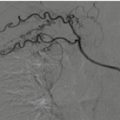
Fig. 9.1
Three-dimensional volume-rendered (3D-VR) image shows the segments of the thoracic aorta
The first two segments, which are intrapericardial, are the Valsalva sinus (segment 0), where the coronary arteries originate, and the ascending aorta (segment 1), which originates 1–2 cm above the coronary ostia. From the aortic arch (segment 2) arise the brachiocephalic, left common carotid and left subclavian arteries (LSAs), which are the three major branches of the arch in most patients. The brachiocephalic artery bifurcates to form the right common carotid and right subclavian arteries. The ligamentum arteriosus is the remnant of the patent ductus arteriosus, which shunts blood from the pulmonary artery to the aorta during development. Finally, the descending aorta (segment 3) is situated beyond the subclavian artery and extending to the diaphragmatic orifice, where it becomes the abdominal aorta [10]. The isthmus is the portion of the proximal descending thoracic aorta located between the origin of the left subclavian artery and the site of attachment of the ligamentum arteriosus [11].
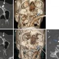
A variety of congenital alterations to the aortic arch exist, such as the true bovine arch and the so-called bovine arch. The true bovine arch (Fig. 9.2a) is a rare variant in which a single, large common brachiocephalic trunk comes off the arch and separates into the right and LSAs and the bicarotid trunk. This bicarotid trunk then bifurcates to form the right and left common carotid arteries. A more common variant is the so-called bovine arch, present in as many as 20% of patients. The so-called bovine arch (Fig. 9.2b) includes a brachiocephalic trunk that splits into the right subclavian, right common carotid, and left common carotid arteries. The LSA comes off separately from the arch of the aorta. Other variants include the left vertebral artery coming off directly from the arch in 2.5% of patients (Fig. 9.3) and the existence of a right-sided aortic arch in patients with dextrocardia or situs inversus. Anatomic variants of the aorta can mask as traumatic injury. For example, a ductus diverticulum may be present along the anterior surface near the ligamentum arteriosus, which may be confused with pseudoaneurysm formation. An aortic spindle may present as circumferential dilatation between the LSA and ligamentum arteriosus [12].


Fig. 9.2
Three-dimensional volume-rendered (3D-VR) images show in (a), bovine arch (white circle); in (b), the so-called bovine arch (white arrow); see also small pseudoaneurysm isthmus (black arrow)
Fig. 9.3
Three-dimensional volume-rendered (3D-VR) image shows normal anatomic aortic arch variant. Black arrowhead shows left vertebral artery coming off directly from the aortic arch; white arrow shows pseudoaneurysm isthmus
9.3 Pathophysiology and Location
There are several causes of traumatic aortic injury, but the common factor is the violence of the shock. Motor vehicle accidents make up 75–80% of the cases, while motorcycle, aircraft, pedestrian accidents, fall from height, and crush injury to chest account for the remainder [5].
Injury to the aortic wall is likely a result of any or a combination of several potential mechanisms include torsion and shearing forces, rapid deceleration, stretching, increased intravascular pressure (water-hammer effect), and compression of the aorta (osseous pinch) [13, 14] (Fig. 9.4). Osseous pinch results from direct compression of the aorta between the vertebral column and the anterior chest wall (sternum, clavicles, and ribs). Torsion indicates rotational forces of the aorta along its longitudinal axis. Shearing forces are caused by differential relative motion at different points of fixation; at the aortic root, the ligamentum arteriosus attachment, and the diaphragmatic crus, the aorta is connected to other tissues, so it’s submitted to increasing regional strain by different deceleration characteristics of the joined tissues. Stretching of the aorta from displacement of vertebrae is the so-called stretch injury. The water-hammer effect, proposed by Lundevall, results when the flow of a non-compressible fluid is occluded dramatically; this condition leads to high-pressure waves being reflected back along the vessel wall, and it could happen after a compression on the abdomen or lower chest. Sudden deceleration is the most common cause of traumatic aortic injury, and it concerns particularly the front seat passenger of a vehicle going at speeds 100 km/h, (sudden deceleration >32 km/h) subjected to frontal or lateral or rear shock [15]. This mechanism causes displacement of the heart, with torsion and shearing forces against the aorta at levels of relative immobility, mainly the ligamentum arteriosus, aortic root, diaphragm, and intercostal arteries.

Fig. 9.4
Three-dimensional volume-rendered (3D-VR) image shows various mechanisms of injury: in (a), osseous pinch, shearing, stretching, and water-hammer effect; in (b), torsion
Direct penetration from fractured ribs, sternum, vertebrae or from gunshot and stab wounds may also occur. Penetrating injuries to the thoracic aorta are uncommon. When present, they are likely to lead to rapid exsanguination, and many of these patients do not survive transport to the hospital.
Depending on the forces in play, the aorta injury site can be the root, ascending aorta, arch, isthmus, descending aorta, or even abdominal aorta (less common). A considerable number of patients have aortic injury at multiple sites.
The isthmus is the commonest location for lesions (approximately 90% of all cases of patients who have been subjected to thoracic trauma) [16]. Its relatively immobile position in the thorax due to its attachment by the ligamentum arteriosus explains the reason for this site being involved in many injuries (Fig. 9.5).

Fig. 9.5
Oblique multiplanar reformation (MPR). White arrow shows site of attachment for ligamentum arteriosus (A aorta, PA pulmonary artery)
Lesions of the root of the aorta are sometimes associated with damage to the aortic valve. Lesions of the ascending aorta are rare (between 5 and 8% of the cases) [17] and mainly occur close by the brachiocephalic origin. In contrast, injuries infrequently occur at the proximal portion of the ascending aorta [18]. These two types of lesions are sometimes associated with hemopericardium.
Involvement of the aortic arch and its branches is not so common. While involvement of the aortic arch itself is rare (about 2% of the cases) [18], the incidence of aortic arch branch involvement varies considerably in the literature (about 3% have a combined aortic and aortic branch vessel injury, whereas the great vessels alone are injured in about 16%) [19].
At multidetector CT, a careful search for a branch vessel injury should be performed in the presence of mediastinal hematoma when there is no direct sign of aortic injury. The innominate artery accounts for 50% of these injuries and is the second most common injured vessel after the thoracic aorta [20]. The left common carotid and left subclavian artery account for the remaining injuries. Innominate artery and left carotid injuries almost always occur proximally at the vessel origin; anatomically, this is where the vessel is tightly fixed onto the aortic arch, whereas the distal part is more mobile and flexible (Fig. 9.6).

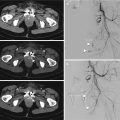
Fig. 9.6
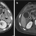
Combined thoracic aorta and aortic branch vessel injury. (a) Axial CT scan and (b) multiplanar reformation (MPR) show small pseudoaneurysm artery innominate proximally at the vessel origin (white arrow in a and white circle in b); (c) three-dimensional volume-rendered (3D-VR) image shows combined pseudoaneurysm isthmus (white arrow) in the same patient
In contrast, blunt subclavian injuries tend to be more distal; these can be explained by adding the direct force of posterior dislocated clavicles [21].
In 1–12% of the cases, there is trauma to the descending thoracic aorta [17]. The distal descending aorta is attached to the adjacent vertebral column by the diaphragm. When there is a shock to the thorax, the resulting shear forces are responsible for lesions at this site. Injuries to this segment of the thoracic aorta can be associated with diaphragm injury in 10% of cases and with adjacent compression fractures of the thoracic spine [22].
In the abdomen, the most common site of injury is the infrarenal abdominal aorta. These injuries are typically related to lap belt compression. There are a number of additional abdominal injuries that are associated with traumatic abdominal aortic injury, including lumbar spine fracture, splenic injury, pelvic fractures, bowel injury, and solid organ injury. Lumbar spine fracture has the highest association with traumatic abdominal aortic injury [23] and if seen should prompt a careful evaluation of the aorta and vice versa.
9.4 Clinical Presentation
Clinical signs and symptoms (Table 9.1) are nonspecific and insensitive for the diagnosis and exclusion of BTAI. A majority of patients with BTAI have no clinical signs of aortic injury until the sudden onset of hemodynamic instability [24].
Table 9.1
BTAI signs and symptoms
Symptoms | Signs |
|---|---|
Chest pain | Unexplained systemic hypotension |
Dyspnea | “Pseudocoarctation syndrome” (upper limb hypertension and lower limb hypotension with diminished femoral pulses) |
Cough | Systolic murmur |
Dysphagia | Chest wall ecchymosis |
Hemoptysis | Sternal, rib, or thoracic spine fractures |
Symptoms of BTAI are thought to be due to stretching of the mediastinal connective tissues by mediastinal blood and include retrosternal pain, referred interscapular pain, dyspnea, and cough [25].
Clinical signs of BTAI are absent in up to one-third of patients but when present include upper limb hypertension and lower limb hypotension with diminished femoral pulses due to “pseudocoarctation syndrome,” systemic hypotension, systolic murmur, external chest wall injuries, fractures (sternal, rib, or vertebral column), and paraplegia [26].
Factors negatively influencing prognosis are a systolic blood pressure < 90 mmHg and hypothermia with T < 35 °C.
Therefore, the clinical picture of patients with BTAI varies from asymptomatic to profound shock.
9.5 Diagnosis
The most important factor in preventing a delay in diagnosis is the arousal of clinical suspicion based on mechanism of injury. Patients sustaining massive chest trauma associated with rapid deceleration (motor vehicle accidents or falls) should carry suspicion of thoracic aortic injury.
9.5.1 Chest X-Ray
A chest X-ray (CXR) has long been a part of the initial imaging assessment of suspected BTAI with a long list of signs described (Table 9.2), including a widened mediastinum (>8 cm at the arch), irregular aortic knob, loss of aortic-pulmonary window, an apical cap, tracheal deviation to the right, nasogastric shifting to right, widening of the left paraspinal line, and the presence of a basilar hemothorax, with sensitivities ranging from 80 to 92% [27, 28].
Table 9.2
Thoracic aortic injuries: radiographic signs
Widened mediastinum >8 cm |
Loss or abnormal aortic contour |
Left apical cap |
Loss of the aortopulmonary window |
Depression of the left main stem bronchus |
Fractures (sternal, vertebral, 1–2 rib, clavicular) |
Nasogastric tube and/or trachea displacement to the right midline |
Pneumothorax |
Pulmonary contusion |
Left-sided hemothorax |
Furthermore, scapular, sternal, thoracic spine, or multiple rib fractures should heighten suspicion of thoracic aortic injury. Patel et al. combined positive chest radiograph findings with clinical suspicion and elevated the sensitivity of plain radiographs to 98% [29].
The most common radiographic abnormality is widened mediastinum (>8 cm) although only 20–43% of patients with a widened mediastinum have a thoracic aortic injury. The finding of a widened mediastinum may be an indirect determinant of thoracic aortic injury being a result more from bleeding small vessels contained within the mediastinum hemorrhage than from aortic bleeding or an aortic pseudoaneurysm, therefore giving low positive predictive values [27] (Fig. 9.7).

Fig. 9.7
Chest X-ray (CXR) in blunt thoracic trauma shows widened mediastinum, abnormal aortic contour, loss of the aortopulmonary window, left-sided pleural effusion, and pulmonary contusion
The utility of chest radiographs in the diagnosis of blunt aortic injury was questioned because radiographic signs on plain chest films carry low specificity and no improvement in overall accuracy [30].
An important factor to bear in mind is that these RX findings are based on upright chest radiographs, thus decreasing projection and magnification artifact appreciated on supine studies. This is complicated by the difficulty in obtaining upright plain films during initial trauma resuscitations secondary to a patient’s injury status. Furthermore, there are several reports documenting thoracic aortic rupture with normal initial chest radiographs [31], so a normal CXR does not exclude an aortic injury. Therefore, plain chest radiographs should not be used as sole criteria for either excluding or confirming thoracic aortic injury and the utility of CXR in the setting of suspected BTAI is low. However, in the acute trauma setting, the supine chest radiograph is still frequently obtained mainly to detect immediate life-threatening lesions requiring immediate treatment (massive hemothorax or tension pneumothorax).
CRX could be used in the long-term follow-up of young BTAI patients after endovascular treatment to reduce radiation exposure as compared with CT; it enables to detect stent-graft migration or collapse [32].
9.5.2 Angiography
Conventional angiography was considered the gold standard for the diagnosis of BTAI for decades with sensitivity and specificity nearing 100%. The publication of the Eastern Association for the Surgery of Trauma (EAST) practice management guideline for the diagnosis and management of blunt aortic injury in 2000 still defined angiography as the “gold standard” for the diagnosis of BTAI [33, 34].
Even though aortography is safe, it is a resource intensive, invasive, expensive and, most importantly, time consuming. It does not demonstrate intramural hematoma and may miss less severe injuries, such as intimal flaps. A false-positive interpretation can occur due to focal atheroma, particularly if ulcerated, an overlapping vessel, and a ductus diverticulum. A rapid development of computed tomography (CT) techniques has rendered CT more sensitive than conventional angiography, mostly due to the detection of extra-luminal abnormalities, either confined to the aortic wall or beyond.
Catheter angiography is now most commonly used to plan endovascular intervention.
9.5.3 Transesophageal Echocardiography (TOE)
Currently, the use of transoesophageal echocardiography (TOE) is very restricted: about 1% of BTAI patients receive TOE [35].
This technique is reported to identify intimal tears, intramural hematoma, pseudoaneurysms, pseudocoarctation, and active bleeding with a sensitivity of 91–100% and a specificity of 98% [36, 37].
TOE is an operator-dependent technique, and even in experienced hands there is incomplete visualization of the entire aortic circumference in a third of patients. Another disadvantage is the relatively poor visualization of the distal ascending aorta and proximal arch.
Patients with facial injuries, unstable cervical spine injuries, or where cervical spine injuries have not been excluded are unsuitable. TOE does not demonstrate the full spectrum of injuries that cross-sectional imaging can.
The primary use currently is to evaluate cardiac dysfunction and injury or hemodynamic state and response to treatment. In hemodynamically unstable patients, transoesophageal echocardiography can be performed quickly at the bedside or in the operating room, which is seen as its main advantages. Thus, unlike the other imaging techniques, TEA can be used intraoperatively to immediately affect surgical and anesthesia decisions.
9.5.4 Intravascular US
Endoluminal or intravascular US is another useful adjunctive imaging modality that can be used to provide high-resolution cross-sectional images of the vessel wall and the surrounding tissues. The findings of aortic injury at intravascular US include vessel wall disruption, intimal flap, focal pseudoaneurysm, intramural and periaortic hematoma, and complete transection. Although these findings are considered to be specific for BTAI, false-positive results have been described [38].
Patel et al. demonstrated better sensitivity compared to angiography especially for picking up MAI, before the era of CT angiography (CTA) as a gold standard [39, 40]. It can be performed concurrently with conventional aortography and has been shown to be a useful complementary modality. Intravascular US is an operator- and experience-dependent invasive procedure, requiring arterial puncture, and complete evaluation of the aorta can be time consuming and may not allow complete visualization of the brachiocephalic artery [24].
9.5.5 Magnetic Resonance Imaging (MRI)
MRI combines safety with an acceptable diagnostic performance [41]. Nonetheless, this technique is not at present used in emergency situations. The duration of acquisitions and the immobility required of the patient prohibit the use of this modality. Furthermore, It may be contraindicated by the support or immobilization equipment required in polytrauma. MRI, however, may have a role in the follow-up when delayed surgery is contemplated, particularly as a strategy for radiation dose reduction in young trauma victims [42].
MRI is useful in the follow-up of patients who have been treated with MR-compatible stent grafts decreasing radiation dose in a usually young patient population although its poorer spatial resolution could lead to a lowered sensitivity for subtle complications and will not detect stent-graft migration.
9.5.6 Computed Tomography Angiography (CTA)
The diagnostic value of chest CT became of increasing interest throughout the 1990s. Previously, chest and abdominal CT have been used as a screening tool detecting periaortic hematomas or posterior mediastinal blood, both of which are highly specific for thoracic aortic rupture, but CT had decreased sensitivity if compared to aortography [43]. During the past 20 years, the wider use of newer, helical CT angiograms (CTA) have increased sensitivity and specificity to as high as 98–100% and a 100% negative predictive value [44], so that CTA is able to exclude aortic injuries without doing any other diagnostic test (Table 9.3) [45–48].
Table 9.3
Angiography versus computed tomography angiography (CTA)
Angiography (%) | CTA (%) | |
|---|---|---|
94–100 | Sensitivity | 96–100 |
93 | Specificity | 100 |
99 | Diagnostic accuracy | 99.9 |
92.3 | Negative predictive value | 99.9 |
99 | Positive predictive value | 92.3 |
Two studies sponsored by the American Association for the Surgery of Trauma in 1997 and 2007 showed how in this decade the diagnosis of BTAI shifted from angiography and TEE to CT scanning [49]. BTAI patients underwent angiography and TEE in 87% and 12% of cases, respectively, in 1997 and only in 8% and 1% in 2007; in contrast, use of CT scan for the diagnosis of thoracic aortic injuries was increased from 34.8 to 93.3% (1997 to 2007).
Dyer et al. also noted significant cost savings of CTA when compared to traditional aortography for diagnosis [50].
With the arrival of multidetector CT (MDCT), the acquisition time was intensely reduced and the scan of whole body, from the base of the skull through the symphysis pubis, can be achieved in few second depending on the scanning parameters (Fig. 9.8).

Fig. 9.8
Multidetector CT (MDCT) angiography three-dimensional volume-rendered (3D-VR) image allows scan of whole body
In addition to faster image acquisition, other MDCT benefits are the panoramicity and an elevated spatial resolution due to axial thin slice (<1 mm) acquisition that can be utilized for “real” multiplanar reformations (MPRs) and 3D reformations.
These features of new CT scanners permit improved diagnosis of BTAI. The advent of dual-source CT scanners and scanners with 64 or more slices has revolutionized the cardiovascular applications of CT [51]. These scanners have the spatial resolution ranging from 0.25 to 0.47 mm, with most newer scanners offering 0.33 mm. These scanners also have a very high temporal resolution due to faster gantry rotation. Newer dual-energy and 256/320 slice CT machines have allowed coverage of the entire aorta in <3 s [52]. Due to the faster image acquisition, still or motion-free images of even the ascending aorta can be obtained without any ECG gating. Also, motion artifacts from patient breathing are minimal. Dual-energy CT scanners can also produce diagnostic images at a lower kV for most patients allowing a reduced contrast administration and a lowering of the radiation dose.
Computed tomography angiography (CTA) is currently the modality of choice for the acute diagnosis of BTAI replacing conventional angiography.
The practice management guideline from the Eastern Association for the Surgery of Trauma published in 2015 “strongly recommend CT with intravenous contrast for the diagnosis of BTAI” [5].
CT of the chest with intravenous contrast has the advantage of being readily available, less invasive, being less time consuming, and allowing for identification of other intrathoracic injuries and for assessment of subtle intimal abnormalities and indirect signs of aortic injury such as periaortic hematoma.
Imaging protocols for MDCT evaluation of the thoracic aorta vary considerably, depending on the technical specifications of the CT scanner (e.g., number of detector rows, the availability of electrocardiographic (ECG) gating). Opinions on the use of multiple phases differ between institutions and a variety of imaging protocols is recommended in the literature.
The protocol that is classically followed is that of the multiple trauma patient. This consists of a pre-contrast acquisition of the head, chest, and abdomen (most useful for diagnosis of intramural hematoma), followed by an arterial phase acquisition covering the neck, chest, and abdomen.
This is usually followed by a portal phase acquisition of the abdomen, so that any injuries to wholly intra-abdominal organs can be better studied [10].
A low-dose delayed phase scan of abdomen and pelvis is performed if the injury is confirmed on portal venous phase or if kidney or bladder injury is suspected.
ECG-gated CT can only be considered when the patient is hemodynamically stable. This technique, which overcomes the issue of artifacts related to movements caused by the patient’s heartbeat, can prove to be very useful in some cases by removing doubts over diagnosis.
Different protocols exist to administer iodinated intravenous contrast material, with either single-bolus, split-bolus, or triple-bolus administration being used.
It should be injected high concentration contrast media (370/400 mg/mL) at a high rate (5 mL/s), followed by another injection saline at the same rate. To avoid streak artifacts from high concentrations of iodine in the left brachiocephalic vein, contrast material should preferably be administered via the right arm whenever possible. Contrast medium should be administered via an 18 G or 20 G cannula. Depending on scanner manufacturer and type, an empirically fixed delay or a bolus-triggering mode can be used. In our institute, we generally use bolus tracking with the region of interest (ROI) placed over the descending thoracic aorta and trigger set at 100–120 HU.
At our institution, all examinations are performed by a 128-slice MDCT with slice thickness of 5–3 or 1 mm (reconstruction 1 mm), collimation of 128 × 0.6 mm, and rotation time of 0.33/0.5 s; intravenous contrast material consists 90–100 mL iodinated contrast agent at 400 mg/mL, concentration injected at 4–5 mL/s, followed by 40 mL of saline at the same flow rate. An automated bolus tracking, with region of interest placed in the descending aortic at an attenuation threshold of 120 HU, is used to time the beginning of the arterial phase. The venous phase is performed at 50–60-s delay from the end of the injection [53].
Our CT trauma protocol is summarized in Table 9.4.
Table 9.4
CT trauma protocol
High concentration contrast agent | 400 mg/mL |
Mdc ev. | 80–100 mL |
Saline | 40–50 mL |
Injection | Bolus tracking |
Injection rate | 5 mL/s through 18 G cannula (right arm) |
Pre-contrast acquisition | Head, chest, and abdomen |
Arterial phase acquisition | Neck, chest, and abdomen |
Portal phase acquisition (70 s after the injection) | Abdomen |
Equilibrium phase acquisition (180 s after the injection) | If it is necessary |
Collimation | 128 × 0.6 |
Rotation rate | 0.5/0.3 |
Pitch | >1.2 (to reduce cardiac pulsation artifacts) |
Slice thickness | 0.6 mm (arterial phase)–5/3 mm (other phases) |
Voltage | 100–120 Kv |
Current (mA) | Optimized relative to body attenuation |
To detect and evaluate vascular injuries, it is mandatory to use thin slices (0.6 mm) so that it is possible to make post-processing works, as multiplanar reformations (MPRs), three-dimensional volume-rendered (VR) images, and maximum intensity projection (MIP) (Figs. 9.9, 9.10, and 9.11).


Fig. 9.9
Thoracic aorta. Reformat—maximum intensity projection (MIP) shows the map of the parietal calcifications
Fig. 9.10
Thoracic aorta vessel-rendering 3D shows pseudoaneurysm isthmus (black arrow)
Fig. 9.11
Thoracic aorta multiplanar reformations (MPRs) show in (a) (sagittal reformat aortic arch) small pseudoaneurysm isthmus (white arrow); in (b), (coronal reformat), large pseudoanerysm aortic descendens (white circle)
Multiplanar reconstructions are sensitive for the detection of small grade I or II lesions, which are sometimes difficult to see on standard axial images. They also allow the lesions and their extent to be better understood.
A sagittal-oblique reconstruction is especially useful since it shows the entire length of the thoracic (and possibly abdominal) aorta and is most helpful to evaluate the relationship of the injury with the left subclavian artery because they give a longitudinal view of the aorta comparable to standard angiographic projections (Fig. 9.12).

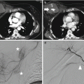
Fig. 9.12
Aorta. (a) Reformat linear image with axial analysis; (b) reformat curved image with axial analysis; (c) reformat linear image with axial analysis shows small pseudoaneurysm isthmus
To obtain a more accurate vascular analysis, a dedicated software should be used; it should able to provide accurate and reproducible measurements through reformat linear/curved images and axial analysis for choosing the appropriate management.
Finally, they are an essential tool for assessing the required dimensions of an endoprothesis when endovascular treatment is planned (Fig. 9.13).

Fig 9.13
Blunt trauma thoracic aortic injury. (a) Reformat and vessel analysis and (b) reformat linear image show small pseudoaneurysm isthmus; (c) reformat and vessel analysis show the distance measurement from left subclavian artery; (d) shows representation of volume-rendered 3D image; (e, f) reformat and vessel analysis show diameter aorta pre-/post-lesion
CTA reports should include the information on location, length, severity and type of aortic injury, aortic diameter above and below the injury, and proximity to the origin of left subclavian artery (in case of isthmic injuries). CTA reports should specify aortic arch anatomy and anatomical variants, any significant preexistent atherosclerotic disease or stenosis, prior postoperative changes (like CABG—coronary artery bypass graft surgery) and comment on anatomic variation or anomalous origin of the great vessels. The radiologist should look for possible coexisting branch vessel injuries and assess femoral or brachial access. Vertebral artery dominance should be determined, if present, on the basis of a measurable larger difference in caliber of one vertebral artery. This information helps the clinician to decide between the treatment options and also guides the intervention.
9.5.6.1 CT Imaging Findings
Based on the layer of the aortic wall involved, BTAI are called aortic dissection (when only intima and deep media are involved), intramural hematoma (when media is involved), pseudoaneurysm (injury contained by adventitia), or rupture (when also adventitia lost its integrity). Based on anatomo-pathological analysis, post-traumatic aortic injuries are generally transverse, segmented, and circumferential, rarely spiral.
The spectrum of findings (Table 9.5) in thoracic aortic injury includes the following direct signs [13, 45, 54, 55]:


Intimal tears/flaps (Figs. 9.14 and 9.15): luminal thrombus abutting the intima often demonstrated as a small, round contrast-filling defect (10 mm in length or width) on the axial images, without external contour abnormality. An intimal flap is a more linear hypodense structure projecting into the lumen of the aorta, connected to the wall.
Intramural hematoma alone (Fig. 9.16): can be seen as thickening of the aortic wall, separating the intima and adventitia by hematoma in the media. It can be focal or rather long and usually are not circumferential. If a non-contrast-enhanced CT is performed, this portion of the aortic wall will demonstrate increased attenuation (around 40–60 HU), a feature that is less obvious if contrast was given. Intramural hematoma plus is characterized by contour changes and/or intimal flaps (Fig. 9.17).
Pseudoaneurysm: focal abrupt change in the aortic contour with a regular (Fig. 9.18) or irregular outpouching, most commonly just distal to the left subclavian artery (Fig. 9.19). Pseudoaneurysm has one or both acute angles with the aortic wall (Fig. 9.20). Especially if there are irregular outlines and surrounding hematoma, there is a high chance of rupture (Fig. 9.21). It has been proposed that a circumferential abrupt change in the aortic contour with an irregular outpouching is at higher risk of rupture.
True aortic dissection (long flap indistinguishable from spontaneous dissection and managed in the same way as spontaneous dissections). This is an uncommon injury (Fig. 9.22).
Pseudocoarctation (obstructive flap reducing the caliber of the descending aorta) (Fig. 9.23).
Active extravasation (rare and often an immediately antemortem finding) (Fig. 9.24).
Table 9.5
CT imaging findings
Direct signs | Indirect signs |
|---|---|
Intimal flap | Hemomediastinum |
Luminal thrombus | Hemothorax |
Aortic dissection | Hemopericardium |
Intramural hematoma | Obliteration of the retrocrural periaortic fat |
Pseudoaneurysm | Unexplained acute renal infarcts |
Pseudocoarctation | |
Rupture |
Fig. 9.14
Axial CT scan shows (black arrow) intraluminal aortic thrombus (minimal aortic injury)
Fig 9.15
Axial CT scan shows in (a, b) (white arrows) intimal tear (intimal flap isthmus)
Fig. 9.16
Post-traumatic intramural aortic hematoma (see also rib fracture and pleural effusion). (a) CT axial non-contrast image show (white arrow) high attenuation material into aortic wall; (b) postcontrast image
Fig. 9.17
Contrast-enhanced thoracic multidetector CT (MDCT) scan of a patient with blunt trauma shows hematoma post-isthmic aortic with intimal flap (intramural hematoma plus)
Fig. 9.18
Isthmus, small pseudoaneurysm with periaortic hematoma. (a) Axial CT scan (white arrow); (b) reformat linear 2D image (size 11 mm)
Fig. 9.19
Aortic isthmus, same large post-traumatic pseudoaneurysm (white arrows). (a) Reformat linear image; (b) axial CT scan; (c) reformat 3D image
Fig. 9.20
Pseudoaneurysm (acute angles with the aortic wall). (a) Axial CT scan shows small pseudoaneurysm isthmus (white arrow); (b) reformat oblique image and (c) reformat 3D image show large pseudoaneurysm isthmus (white circle in b and white arrow in c)
Fig. 9.21
Axial CT scan shows pseudoanerysm: irregular outlines and surrounding hematoma
Fig. 9.22
Multiplanar reformation (MPR) shows post-traumatic aortic dissection
Fig. 9.23
Traumatic pseudoaneurysm with pseudocoarctation (obstructive flap reducing the caliber of the descending aorta). (a) Axial CT scan; (b) reformat linear image
Fig. 9.24
Axial CT scan shows aortic dissection with active extravasation (hematoma periaortic, hemothorax)
Indirect signs of aortic injury are hemomediastinum and hemothorax. The location of hemomediastinum is an important data because the immediate periaortic region or beyond is mostly related to the bleeding from the aortic injury. Periaortic hematoma is used to describe hematoma directly bordering the aortic adventitia and obliterating the periaortic fat plane (Fig. 9.25). If periaortic hematoma is present, the aorta should be scrutinized for the presence of injury. However, lesser grade injury is possible if periaortic hematoma is absent, around 21–22% of such cases occurring without surrounding hematoma [56, 57]. In the presence of periaortic hematoma without direct signs of major vessel injury seen on a technically adequate study, debate exists about whether or not to perform follow-up scans in 48–72 h. Mediastinal hematomas not immediately adjacent to the aorta (with a obliterating the periaortic fat plane) are likely to be secondary to venous bleeding (Fig. 9.26). Isolated anterior mediastinal hematoma is unlikely to be due to BTAI; injuries to the internal mammary artery (which may be life threatening), bronchial arteries, superior intercostals veins and ribs, clavicles, and sternal fractures are all more likely culprits.


Fig. 9.25
Axial CT scan shows periaortic hematoma (obliterating the periaortic fat plane)
Fig. 9.26
Axial CT scan shows mediastinal hematoma (white arrow shows preserved periaortic fat plane)
Bleeding from the aortic injury can extend into the pleural space (Fig. 9.27) or pericardium, depending on the location of the injury, giving rise to hemopericardium or hemothorax. Usually, hemopericardium is homogenously hyperdense, whereas hemothorax can have mixed densities with more hyperdense areas indicating cloth. However, if pleural effusion has densities similar to fluid (0–20/30 HU), differentiating hyperacute hematoma from reactive effusion can be difficult.

Fig. 9.27
Aortic rupture with active extravasation. (a, b) Axial CT scan show traumatic aortic injury (isthmus-descending aorta) with hemothorax and hemomediastinum. (c) Multiplanar reformation (MPR) oblique reformat image; (d) elaborate maximum intensity projection (MIP) image
Other two indirect signs can be seen on abdominal CT and should mandate further investigation of the thoracic aorta. These are obliteration of the retrocrural periaortic fat (possibly indicating caudal extension of more cranially located periaortic hematoma) and otherwise unexplained acute renal infarcts, especially when bilateral, that can originate from luminal thrombus of more cranially located BTAI.
Secondary signs of injury (SSI) were recently defined as pseudocoarctation, extensive mediastinal hematoma (with mass effect), and large left hemothorax [58, 59]. The SSI seem to be associated with a higher risk of rupture.
Chronic pseudoaneurysms can develop at the sites of undiagnosed and/or untreated aortic injury. These often have extensive peripheral calcification and may also contain thrombus. The peripheral calcification is thought to be protective against aneurysm rupture.
Concurrent injuries in patients with blunt TAI include major abdominal injury (57%), closed head injury (50%), major peripheral vascular injury (46%), multiple rib fractures (46%), pulmonary contusion (38%), pelvic trauma (31%), upper extremity trauma (20%), flail chest (12%), and spine injury (12%) [9].
9.6 Differential Diagnosis and Pitfalls
A number of artifacts can mimic a traumatic injury of the thoracic aorta.
Diagnostic pitfalls (Table 9.6) can be divided into two categories: anatomic and technical [13, 60].
Table 9.6
The most common diagnostic pitfalls
Cardiac pulsation artifacts |
Ductus diverticulum |
Branch vessel infundibula |
Anatomic variants |
Superior intercostal artery/vein |
Ulcerative plaques |
Pulmonary atelectasis adjacent |
Kammerell’s diverticulum |
The classic example of technical pitfall is that of the cardiac pulsation artifact, which is particularly present at the root of the aorta and in the ascending aorta that simulates an intimal pseudo-flap (Fig. 9.28). This image continues in the mediastinal fat giving a blurred interface with the hyperdense lumen of the aorta, which can help with diagnosis. Otherwise, these artifacts can be removed by ECG-gated CT in stable patients if there is any doubt. Breathing and patient movement artifacts can also be found. They are revealed by visualizing the thorax in the lung parenchymal window.

Fig. 9.28
Artifact. (a) Axial CT image shows motion artifact at the aortic ascendant. (b) Axial CT image shows dense contrast media in the superior vena cava
Anatomic pitfalls that can be mistaken for BTAI mainly reside around the level of the isthmus, namely a ductus diverticulum, patent ductus arteriosus, and aortic spindle. The ductus diverticulum, found in 9% of the arteriograms in the adult, is a remnant of the closed or partially closed ductus arteriosus which connects the pulmonary artery to the aorta in fetal circulation. Ductal remnants are located at the inferior surface of the aortic arch near the aortic isthmus which leads to confusing them with BTAIs. Ductus diverticulum has typically smooth, obtuse angles with the aortic wall and are often calcified, whereas BTAI usually is more irregular and steeply angled (Fig. 9.29).

Fig 9.29
Ductus diverticulum. Multiplanar reformation (MPR), sagittal-oblique reconstruction, shows smooth, obtuse angles with the aortic wall (white rectangle)
A patent ductus arteriosus is a rarity in itself, and it can be recognized as a tubular structure with regular contours, where the differential of active contrast extravasation in BTAI is usually irregular and situated within hematoma.
Aortic spindles are located just distal to the isthmus and are smooth, regular fusiform mild dilatations of the aorta, without periaortic hematoma (Fig. 9.30).

Fig 9.30
(a) Multiplanar reformation (MPR), oblique reconstruction, (b) axial CT scan, and (c) three-dimensional volume-rendered (3D-VR) image show aortic spindle, regular fusiform mild dilatation of the aortic isthmus
Branch vessel infundibula can also be confused with a small pseudoaneurysm. They can have a similar appearance to a ductal remnant, but are found at the origin of bronchial or intercostal arteries. They are typically cone shaped and smooth walled with a small artery extending from the apex (Fig. 9.31).