Fig. 6.1
Correct execution of DXA scans: (a) lumbar spine, (b) hip, (c) total body
Another common site for BMD measurement by DXA is the hip. This is because the proximal femur BMD is the best predictor of hip fracture, the “hottest” site for osteoporosis in terms of morbidity, mortality, impaired quality of life, and costs. For the hip DXA scan, the patient is positioned supine on the scanner table, centered on the table, with the long axis of the femoral diaphysis aligned with the long axis of the scanner table (usually the nondominant femur is examined). A positioning device is used to place the femur in internal rotation, to elongate the femoral neck, and to allow for more reproducible results on subsequent examinations. When the patient is properly positioned, the DXA image should show the femoral shaft aligned with the long axis of the scanner, and the lesser trochanter should be small or not seen, indicating sufficient internal rotation (Fig. 6.1b). If the desired amount of internal rotation cannot be achieved, as it often happens in the case of patients with hip arthritis or short femoral necks, the technologist should place the patient comfortably in a position that is likely to be reproducible in a subsequent study, and this may be recorded in the report (Watts 2004). Hip BMD measurement is obtained for various ROIs including the femoral neck, trochanter, Ward’s area, intertrochanteric region, and total hip. In certain clinical settings, a double hip examination may be useful.
The third important site used for BMD measurement by DXA is the forearm. This measurement is useful for patients in whom the spine or the hip is either not measurable or not interpretable. Moreover, the forearm is often investigated in metabolic bone diseases where cortical turnover is particularly emphasized. For the forearm DXA scan, the patient is positioned sitting in a chair adjacent to the scanner table. A positioning device is used to align the forearm with the scanner table and allow for more reproducible results on subsequent examinations. Forearm BMD measurement is obtained for various ROIs including the mid-radius and mid-ulna (33 % or one-third) and ultra-distal radius and distal ulna. Ideally, the nondominant forearm should be measured.
Finally, whole body DXA scan may also be required for both bone and body composition analysis. The patient is positioned centered and aligned with the scanner table, arms at sides separated slightly from the trunk. BMD measurement is obtained for the whole body as well as smaller ROIs, including the left upper limb, right upper limb, left thorax, right thorax, thoracic spine, lumbar spine, pelvis, left lower limb, right lower limb, and head (Fig. 6.1c). ROIs can also be defined for body composition purpose (evaluation of fat mass, non-bone lean mass, and bone mineral content, in the classical three-compartment model/molecular level of composition) in total body, trunk, upper limbs (per side or both sides), lower limbs (per side or both sides), android region (a portion of the abdomen included between the line joining the two superior iliac crests and extended cranially up to 20 % of the distance between this line and the chin), and gynoid region (a portion of the legs leaving from the femoral great trochanter, directed caudally up to a distance double of the android region). For regional body composition evaluation, it is essential to ensure that these regions only include the appropriate anatomy. To facilitate subsequent correct analysis, the individual’s arms are positioned to maximize the space between the arms and torso (Fig. 6.2). This allows clear separation of the arms from the abdomen and buttocks (Libber et al. 2012).
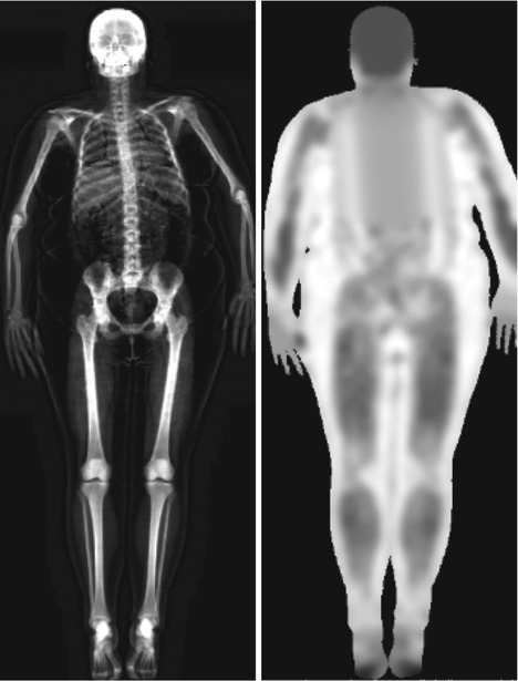
Fig. 6.2
Example of improper positioning of the patient’s right arm in a total body scan: the right hand is not correctly separated from the trunk of the patient and thus leads to underestimation of the total BMD values
Traditionally, DXA scanning beds supported limited weight and limited width of the scanning area. However, modern DXA may house patients up to more than 200 kg in weight and are provided with wider scanning areas. When the patient’s body shape exceeds the rectangular scanning area, the accuracy of the measurement is often compromised. This limitation has led to the development of “half body” scan modality to accurately estimate total body composition. The software automatically detects the off-center shift of the subject and analyzes only the right side of the image to yield the half body scan results (Rothney et al. 2009) (Fig. 6.3). This feature has demonstrated good correlation with total body measurement (Libber et al. 2012). The advantages of DXA include low radiation dose, low cost, easy use, and rapidity of measurement. However, DXA, as a two-dimensional technique, does have inherent limitations. Although recent advanced hip analysis have been developed (Fig. 6.4), allowing the measurement of cortical thicknesses at certain anatomic levels, DXA cannot distinguish between cortical and trabecular bone and cannot discriminate between changes due to bone geometry (e.g., increases in the third dimension) and those due entirely to increased bone density (within a fixed volume of bone).
Fig. 6.3
A “half body” scan modality in an obese patient: (e) indicates the estimated composition for every single region
Fig. 6.4
Example of “advanced hip analysis”
6.3.2 Pitfalls
Mistakes in BMD measurement by DXA are not uncommon. All centers involved in clinical DXA scanning and interpretation should pay attention to pitfalls related to the scanner and its software, the positioning of patient and analysis of scans, and various patient-related artifacts (El Maghraoui and Roux 2008). Errors can result from improper equipment maintenance, inadequate education and training in bone densitometry, and insufficient knowledge of current standards and guidelines. These pitfalls may easily lead to errors in interpretation; both false-positive and false-negative results are common. For these reasons, all DXA images should be carefully assessed for patient positioning, scan analysis, and artifacts before reporting any given BMD, T-score, or Z-score (Lenchik et al. 1998).
Acquisition errors (e.g., improper positioning, scanning despite a correctable artifact being present) typically require a return visit by the patient to re-scan correctly. This means time lost and new radiation exposure for the patient (although very low dose to the patient is provided by DXA). Errors of analysis, if recognized, can be corrected by reanalysis without a return visit of the patient. However, other errors, such as those involving quality control, may have been present but not appreciated in the post-acquisition diagnostic phase of the examination. These could cause systematic changes in measured BMD over time that are of sufficient magnitude to invalidate the DXA interpretation (Lewiecki et al. 2006). It is possible to avoid most of the errors in acquisition and analysis by involving well-trained and experienced DXA technologists. Good quality control can be accomplished by establishing standard operating procedures that are overseen by a knowledgeable supervisor and carried out by a skilled technologist. The skill and attention of the physician interpreting the exam remains essential to recognize mistakes before a report is given.
6.3.2.1 Technical Pitfalls
Steps should be taken to make sure that a DXA device is of sufficiently high quality and that its accuracy and precision are according to manufacturer guidelines. This is influenced by several parameters, such as skill and training of the technician performing the scan, site of measurement, and clinical features of patients (Damilakis and Guglielmi 2010). To determine the accuracy of a DXA densitometer, a phantom containing tissue-mimicking materials of known and different densities is scanned to ensure that measured values are truly assessed for all quantities under investigation (Diessel et al. 2000). The phantom represents the typical density range and size of normal human spine. The accuracy error of DXA bone densitometers is better than 10 % (Kanis et al. 1994). Phantom measurements have to be performed every day or at least three times a week. Results are entered into the quality control (QC) database to enable compensation of calibration changes (Guglielmi et al. 2012). If there are significant shifts or drifts in phantom data, the scanner should be serviced before scanning any patients.
One of the purposes of the DXA scan image is to see if the patient is positioned correctly, and the technologist should verify this condition before the patient leaves the testing unit. In fact, improper patient positioning and scan analysis may result in poor precision or poor reproducibility, both of which will limit the ability of the machine to measure small changes over time (Lenchik et al. 1998). Initially during DXA scan acquisition, the technologist uses the image to confirm adequate positioning and to ensure appropriate placement of ROIs, including appropriate intervertebral designations. The image should be assessed for patient motion because motion produces unpredictable alteration in bone mineral content measurements (Cawkwell 1998) (Fig. 6.5). Patients with scoliosis cannot be positioned with the spine straight on the table, and often with severe scoliosis, there are degenerative changes that invalidates the spine measurement (Fig. 6.6).
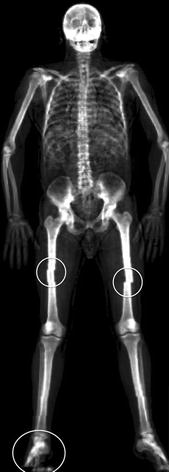
Fig. 6.5
Patient motion results in blurring or irregular contour of the bone margins on the DXA images. The circled areas show some of these common artifacts
Fig. 6.6
Severe scoliosis may invalidate the evaluation of lumbar BMD. The placement and correction of lines defining the regions of interests in lumbar DXA may be critical. This is essential for the interpretation of results and for the reproducibility of the examination (a, before and b, after correction of L1)
Identification of overlying hardware or retained barium may obscure the osseous structures, making BMD measurements at a site invalid (Fig. 6.7). The correct and appropriate undressing of patients before DXA scan is fundamental – in the spine, as in all other DXA examinations. Correct numbering of lumbar vertebral levels and correct ROI placement are especially important when performing serial BMD measurements to minimize scan result variability (Fig. 6.8). Staron et al. (1999) reported that incorrect placement of the intervertebral disk spaces on the image for ROI placement was the most common operator-dependent error in spine BMD measurements. The most common anatomy – five lumbar vertebrae and the last set of ribs on T12 vertebra – is found in about 85 % of people; about 15 % of the population has four or six lumbar vertebrae or the last set of ribs on T11 or L1 vertebrae. When in doubt, it is best to count from the bottom up, assuming that the L4–L5 interspace is at the pelvic brim (Fig. 6.9). There must be sufficient soft tissue on both sides of the spine; otherwise, BMD will be underestimated. All evaluable vertebrae should be used, but vertebrae that are affected by local structural change should be deleted from the analysis. Most agree that decisions can be based on two vertebrae. If all vertebrae are affected, the spine should be reported as “invalid,” with no BMD number or T-score given.
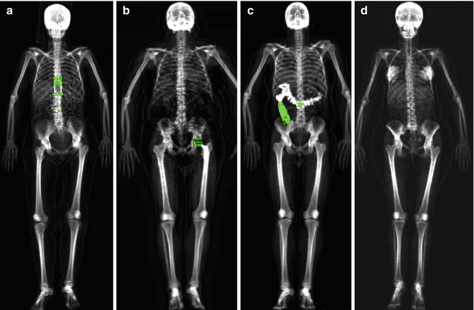
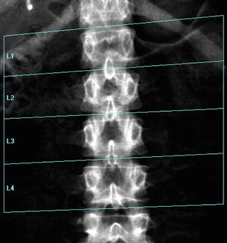

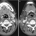
Fig. 6.7
Some examples of pitfalls in total body scans: (a) presence of distraction rods, (b) left hip replacement, (c) retained barium, (d) breast prostheses
Fig. 6.8
A typical improper execution of a lumbar scan: the DXA image does not include the superior margin of both iliac crests, thus making difficult the correct recognition of vertebral levels
Fig. 6.9
A patient with six lumbar vertebrae: the improper positioning of the vertebral levels (a) changes in an important way the BMD values of this lumbar scan; in fact after the correct positioning of these levels, (b) the BMD values increase
In the hip, analytic pitfalls relate to placement of femoral ROIs and particularly those influencing the neck region. The default hip analysis includes a midline that must be placed correctly for the other sites to be identified correctly. The preferred position for the rectangular femoral neck box differs for the different manufacturers. For all, the femoral neck ROI should include only the femoral neck; it should not extend medially to include part of the ischium, nor should it extend inferolaterally to include part of the trochanter (Fig. 6.10). Newer machines will automatically “ignore” the ischium within the femoral neck box, or it can be “painted out” manually, if necessary (Yu et al. 1995).
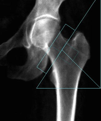
Fig. 6.10
Improper femoral positioning: the femoral neck ROI should include only the femoral neck. In this scan, the ROI includes part of the ischium, invalidating the BMD values
Correct identification of the patient is important for obvious reasons, but also important are the correct date of birth, sex, and ethnicity, all of which are used to calculate T- and Z-scores. In particular situations, the choice of the correct reference standard according to race and sex (e.g., transsexual patients) may be a matter of discussion and need to take into consideration the patient’s values in multiple reference systems. The use of the same machine for DXA consecutive evaluations in the follow-up of a patient is also another important point to take into consideration. It is important for patients to repeat BMD measurements on the same machine at any time in their follow-up or at least on a machine from the same manufacturer. The error between machines or in converting measurements from one manufacturer’s standard to another can introduce errors large enough to wipe out the sensitivity of the measurements.
No clear evidence shows the time lapse required between two subsequent surveys to show significant changes of the BMD values. Proper execution time of the different monitoring phases is another possible source of technical-methodological mistake. Because of limitations in the precision of testing, a minimum of 2 years may be needed to reliably measure a chnge in BMD (U.S. Preventive Services Task Force Recommendation Statement 2011).
As previously mentioned, to further improve the accuracy and to optimize the use of bone densitometry, a team of expert radiologists and technologists should be constituted. Some states also require specific training in bone densitometry. Hence, radiologists should be fully experienced in both physiopathology and treatment of osteoporosis and bone metabolic diseases and performance of all radiologic techniques employed for the diagnosis of the disease and bone densitometry diagnostic activity. On the other hand, technologists should have sufficient knowledge and experience of the bone densitometry equipments such as patient positioning and performance of quality control procedures (Khan et al. 2004).
6.3.2.2 Interpretation Pitfalls
Primary care physicians are usually not directly involved in the performance and interpretation of DXA scans but should be familiar with the information on DXA scan reports and how it applies to patient management (Watts 2004). Mistakes in interpretation and reporting are the most difficult to correct, because they occur in the final steps of the process, usually with no one to identify the errors before an incorrect report is sent. It is logical that such errors can be minimized by initial training and continuing education in the field of bone densitometry (Lewiecki et al. 2006). The DXA image is assessed for visible disease processes. In addition to noting the presence of these abnormal conditions in the DXA report, it is important to determine how these processes affect the BMD measurement.
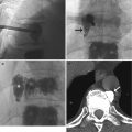
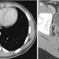
Certain conditions can artificially elevate the BMD, obscuring osteoporosis and leading to underestimation of fracture risk (Barden et al. 2003). These include degenerative disk disease, compression fractures (Jacobson et al. 2000) (Fig. 6.11), scoliosis, postsurgical defects, overlying atherosclerotic calcifications, implantable devices such as stents and vena cava filters, soft tissue calcifications (Fig. 6.12), retained radiopaque contrast agents, lumbar hardware, vertebroplasty cement, and external objects such as piercings, bra clips, and high-density objects on clothing (Theodorou and Theodorou 2002; Bazzocchi et al. 2012).
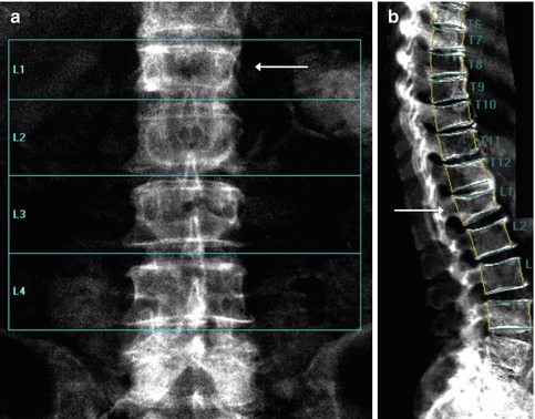
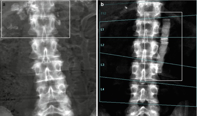
Fig. 6.11
Compression fracture of the L1 vertebral body (arrowed) seen in (a) the lumbar spine and (b) the lumbar vertebral fracture assessment DXA scan
Fig. 6.12
Lumbar spine DXA: (a) rectangular area circumscribed some paravertebral soft tissue calcifications close to the vertebral body of L1, (b) an unknown high-density object close to the L1–L3 vertebral levels
In the lumbar spine, almost all artifacts and local structural change will spuriously elevate BMD. This is especially true for spinal degenerative change (spondylosis), which can elevate spine BMD by 2, 3, or more T-score units (Yu et al. 1995). The affected vertebral levels should be excluded from the ROI, or another BMD measurement site should be selected. Lateral DXA may be used to reduce the effect of sclerotic facet osteoarthrosis (Fig. 6.13) or overlying vascular calcifications on the BMD measurement because this area would be excluded from the ROI (Fig. 6.14). In the spine, absent bone (after surgery such as laminectomy or spina bifida) will spuriously lower the BMD. In the hip, sclerotic conditions such as bone islands (enostosis) may increase the BMD measurement, if they are included in the ROI. Significant osteoarthrosis may increase the BMD measurement, if cortical thickening or buttressing extends into the femoral neck ROI. Similarly, Paget disease, calcific tendinitis (calcium hydroxyapatite deposition), and vascular calcifications may increase the BMD measurement, if included in the ROI. If a disease process is affecting the BMD measurement in a particular ROI, another ROI or, alternatively, another site may be used. Similarly, BMD at the proximal femur can be altered by the degree of internal rotation, placement of soft tissue gluteal silicon implants (Hauache et al. 2000) (Fig. 6.15), and overlying soft tissue thickness or fat.
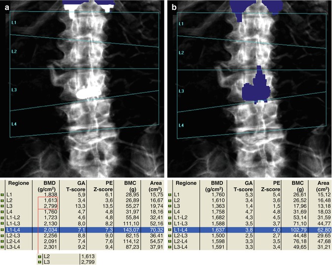
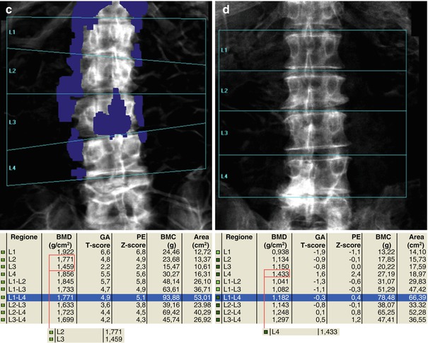
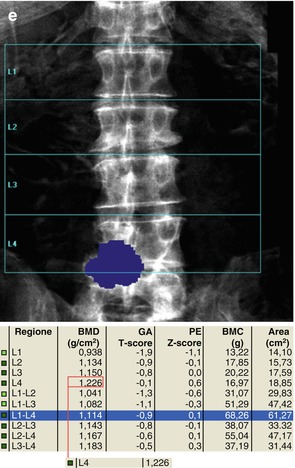
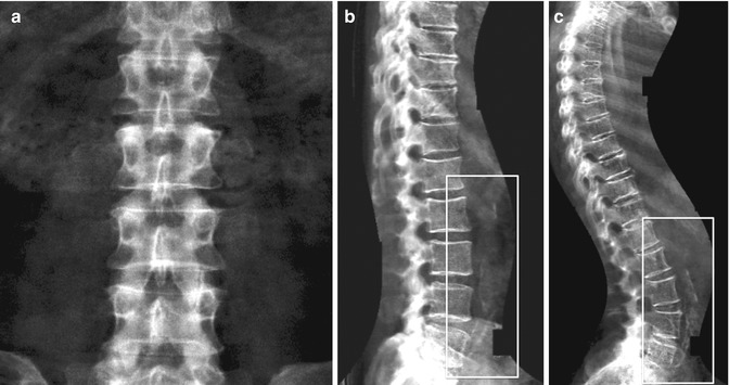
Fig. 6.13
The presence of arthrosis may significantly alter the evaluation of BMD. In (a–c) series, the marginal osteophytes lower the BMD value and these do not have to be considered as “bone” (a–c, e.g., L2–L3). On the other hand, the inclusion of the high-density device at L3 vertebral level increases the BMD value and this, as well as osteophytosis, should be excluded for analysis (as automatically provided today by most of commercially available DXA machines). In images (d, e), arthrosis is projected on the area of the lumbar vertebrae to scan (L4–L5) and this increases the BMD measurement; thus, its exclusion should be considered and reported
Fig. 6.14
Vascular calcifications (rectangular areas) may increase the BMD measurement of the spine, but they are often invisible in the posterior-anterior projections as can be seen by (a) lumbar spine DXA and (b) vertebral fracture assessment DXA scan of the same patient. (c) Another example of severe aortic calcifications detected by vertebral fracture assessment DXA scan
Fig. 6.15
Presence of a high-density image corresponding to a gluteal silicon implant is shown near the right femoral neck and trochanter (a). Right femoral neck BMD values “increased” from 0.808 to 0.871 g/cm2 after the exclusion of this silicon implant from the ROI (b)
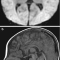
Other disease conditions such as avascular necrosis of the femoral head and developmental dysplasia of the hip may be visible on the DXA image but will not affect the BMD measurement because these conditions are outside the ROI boundaries. It is essential, however, that a suspected abnormality on the DXA image be evaluated further with correlative imaging to confirm a diagnosis and to exclude potential aggressive or malignant causes (Jacobson et al. 2000). It is important to suggest that all alternative or corrective methods and changes in technical acquisition as well as considerations related to particular elements (e.g., excluded sites or limitations) should be described in the reports.
6.4 Quantitative Ultrasound
6.4.1 Basic Concepts
Today, quantitative ultrasound (QUS) represents an effective alternative or integrative method for studying bone tissue and managing patients presenting with osteoporosis or other metabolic bone diseases (Guglielmi et al. 2011). Although QUS does not produce an image showing bone structure, it is used to measure quantitative parameters and assess tissue properties. Interest in quantitative US methods can be attributed primarily to the fact that they involve no radiation exposure. In addition, US-dedicated scanners offer the advantages of small size, quick and simple measurements, and low cost compared with axial DXA or quantitative CT scanners. These advantages explain the motivation for using QUS for the assessment of osteoporosis, assuming that performance is comparable. The primary disadvantage of QUS is its lack of sensitivity (Moyad 2003), making it inappropriate for long-term monitoring of osteoporosis or response to drug therapy. In addition to equipment drift, in vivo precision is also affected by external factors (Njeh et al. 2000). Currently, US assessment is used as a screening tool, with confirmation of diagnosis by means of DXA evaluation.
QUS devices generate pulsed acoustic waves with a frequency between 500 kHz and 1.25 MHz according to the manufacturer, which is considerably lower than the frequencies commonly used in US imaging. US waves are affected not only by the amount of material but also by its elasticity and structure. As a consequence, QUS may yield additional information about bone properties and fragility. The QUS method involves generating ultrasound impulses that are transmitted transversally or longitudinally through the bone being studied. The ultrasound wave is produced in the form of a sinusoid impulse by special piezoelectric probes and is detected once it has passed through the medium. There are two distinct probes (emitting and receiving) and the skeletal segment for evaluation is placed between them. The first ultrasound parameters employed for characterizing the bone tissue are speed of sound (SoS) and broadband ultrasound attenuation (BUA). More complex parameters have been developed from combination of the aforementioned amplitude dependent speed of sound (AD-SoS), stiffness, and quantitative ultrasound index (QUI) (Gluer 1997). In the diagnosis of osteoporosis, these latter parameters have proved to be more useful in identifying subjects with low bone mineral density and therefore at high risk for fracture (Hans et al. 1996; Guglielmi et al. 2003).
Related posts:
Stay updated, free articles. Join our Telegram channel

Full access? Get Clinical Tree


