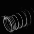
Fig. 35.1
Brain deformation. After removal of an intraventricular lesion, the brain surface collapses and opens the view onto the frontal skull base. Note the bridging veins, tethering portions of the surface to the bone. Patient is positioned supine for this left frontal craniotomy (Courtesy P. Black and S. Leon)
With the introduction of computer-assisted navigation systems [2, 3], this ubiquitous observation, the intraoperative deformation of the brain, commonly summarized as “brain shift”, became a problem [4].
Computer-assisted image-guidance systems use preoperative data for planning and intraoperative orientation. These navigation systems enabled the intuitive use of medical image information (i.e. structural CT, MRI and subsequently even functional and metabolic data) for intraoperative guidance and decision making. However, particularly in neuroepithelial tumours, where the extent of resection holds the major promise for prolonged progression-free and overall survival [5], the accuracy of these systems was progressively corrupted by intraoperative changes [6].
The ultimate solution is the intraoperative renewal of information, to update the neuronavigation [7, 8]. However, mathematical models, to capture and simulate brain shift, have yielded interesting and promising results and insights into brain biomechanics.
The Phenomenon of Brain Deformation
The brain is a non-rigid organ enclosed within a rigid structure. Primarily attention to the elastic properties of the brain came from studies relating to traumatic brain injuries (TBI) [9, 10].
With the advent of computer-assisted navigation, the interest in the brain deformation, “brain shift”, gained momentum. Initial observations and calculations were limited to the visible cortical surface or the most obvious deep structures, the ventricles (as seen on intraoperative ultrasound) [11–13]. With the integration of intraoperative MRI into the analysis of this phenomenon, more complete data sets could be gathered for the analysis of these deformations [14–16]. Within the double doughnut, we acquired repetitive volumetric acquisitions at predefined surgical stages [16]. These data sets were subsequently analysed using various mathematical models to characterize the deformations [17–19]. The most promising approach used finite element models (FEM) to calculate the deformation matrix. This approach has been employed almost ubiquitous [19–23]. On this basis, surgical simulation, modelling retraction and resection [24] have been investigated.
Various groups have shown that while the surface deformation can be precisely calculated, there were more pronounced variations in the calculation of deep located structures and their deformation [19, 21]. Thus, for superficial surgeries, i.e. in epilepsy surgery or for cortical dysplasias, mathematical modelling can precisely compensate for the sagging of the surface. However, in deep-seated lesions, or extended resections, modelling may only yield approximations, even when used in conjunction with “sparse” intraoperative imaging, for instance, ultrasound [25], as a framework for the modelling algorithm.
These and subsequent studies corroborated our initial findings in regard to intraoperative brain deformations [21, 26]. There are at least two distinct compartments, superficial and deep, which can behave differently, and may even show contrary deformations (deep swelling, superficial sagging) (Figs. 35.2 and 35.3). Further influencing factors are gravity, CSF drainage, perifocal oedema, size and location of the lesion and preoperative alterations of the brain (radiated brain appears more rigid). Furthermore, we could demonstrate that deformation patterns can have separate non-linear time-lines, counteracting or potentiating each other. Complicating influences by medication have not even been addressed yet.
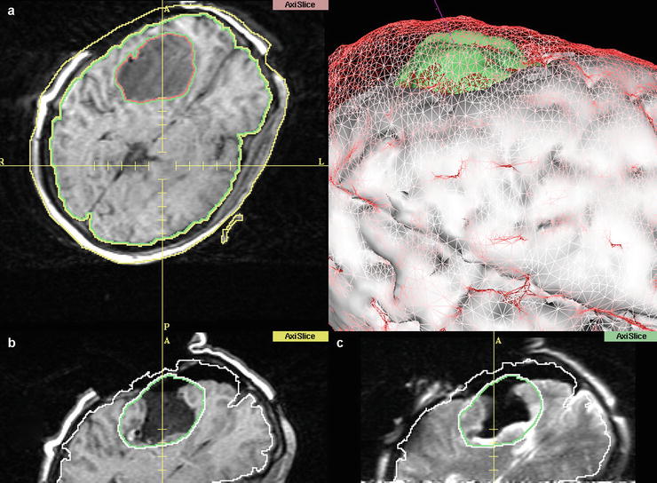
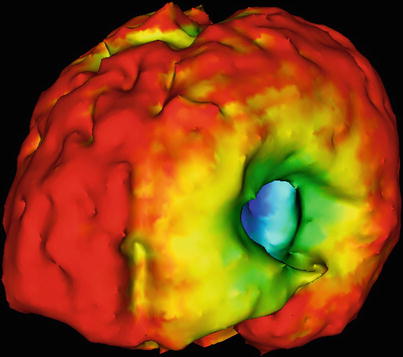
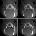
Fig. 35.2
Screen display of the 3D Slicer, demonstrating pre- and intraoperative images, as well as a 3D representation of the different stages. (a) After craniotomy, before dural opening. The tumour is segmented, as well as the cortical surface. (b) Registered intraoperative images after tumour removal. Note the collapsing wall and the basal ganglia (Caudate nucleus) expanding into the resection cavity. (c) T2 image taken at the same surgical stage (different plane) as (b) shows the expansion of the medial wall of the resection cavity into the area labelled as tumour. This deformation cannot be accounted for by conventional navigation systems. (d) 3D representation of preresection (a) data: Cortical surface is depicted as red mesh, tumour in green. Solid white is the cortical surface at (b/c) after tumour resection
Intraoperative MR imaging can be employed to capture and characterize intraoperative deformations [15, 16] as well as form a basis to investigate new algorithms [17, 18]. Initial challenges due to computation potential have been successively overcome, using parallel computing, more powerful hardware and improved algorithms based on increasing knowledge of this phenomenon [22]. Approximations already permit the elastic deformation of presurgical functional data to the intraoperative setting [27]. Precise simulation prior to surgery remains a future challenge [28, 29].
Future analysis has to accommodate that the brain has multiple compartments (at least two: superficial and deep) [16], which are internally structured by vasculature and connecting fibre bands, the CSF chambers and pathways, as well as the subdivisions of the cranial space by bony edges as well as dural duplications [30]. Furthermore, the brain is tethered by arachnoid septae as well as bridging veins (Fig. 35.1).
Physical models try to account for that, by using materials of different viscoelastic properties and traversing tubular structures to account for the organizational heterogeneity [31].
Presently tissue elasticity coefficients are arbitrarily determined. Future application of non-invasive methods [32], such as MR-elastography [33, 34], to measure these coefficients directly might yield the basis for precise individual model-based compensation of intraoperative brain deformations.
Presently, the only precise method to compensate for “brain shift” is by intraoperative imaging.
Intraoperative Imaging and Update of Intraoperative Navigation
Intraoperative imaging had been assessed with ultrasound (US), computed tomography (CT) and intraoperative angiography/X-ray. Apart from the latter, which were only used for special indications (vascular and stereotactic procedures), the systems did not flourish, even though the technical capacities increased progressively.
Only with the introduction of image-guided systems [2, 3] which enabled a more intuitive integration of the image data, the concept of intraoperative imaging resurfaced.
Ultrasound has undergone a constant evolution in regard to transducer geometry and image quality. Incorporated into navigation systems, this modality has the advantage of near real-time data acquisition [35]. Shown on a split-screen with presurgical MRI data, the unfamiliarity with this mode can be overcome. The introduction of contrast medium as well as techniques permitting the registration of physical properties, such as elastography or vibrography, may yield even better results in regard to tumour resection control. Comparison of MRI and US has to be undertaken to assess the relative indications for either modality [36].
Intraoperative CT [37] has obvious limitations in radiation exposure and tissue differentiation. However, integrated systems hold merit in vascular and spine applications [38].
Both of these modalities may yield sparse data, to drive mathematical models which deform presurgical data according to the intraoperative changes.
Intraoperative imaging was revolutionized by the integration of MRI [7, 39]. While this is the most cumbersome and expensive modality to be integrated into surgery, it also yields the most precise structural as well as functional information [40].
Two basic approaches were taken: one separating imaging and surgical site [41] and one with combined surgical and imaging site [42, 43].
The latter embodied the notion of intraoperative imaging, since images could be acquired during surgical procedures without moving the patient. This system had an integrated localization system [44]. A special software application, the 3D Slicer, was developed to expand the localizer functionality into a fully integrated navigation system combining pre- and intraoperative images for continued image guidance [6, 45]. The intraoperative images were directly transferred into the 3D Slicer, since the coordinates of the “imaging” space were the same as the “physical”, surgical space. Employing registration algorithms for an automated fusion, rather than going through all the steps of physically reregistering, the data was used to update the navigation with minimal delay (Fig. 35.4).
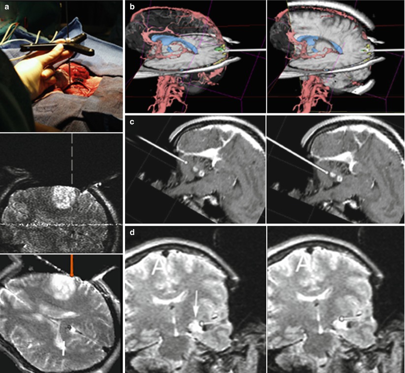
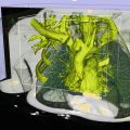
Fig. 35.4
Composite showing the capacity of the 3D Slicer in combination with the double doughnut for image-guided surgery. (a top) Localizer which operates like a 3D Mouse in the surgical site, pointer tip on the cortical surface. (a middle) Corresponding “real-time” MR image acquired through the axial plane as marked by the localizer. (a bottom) Corresponding navigation image, as displayed on the navigation monitor. (b–d) show screen shots of the 3D Slicer during navigation, as seen and used by the surgeon. The pointer’s (a top) orientation as well as the tip location is represented by a virtual pointer (white). (b) Occipital cavernoma. Example of co-registration of 3D data extracted from presurgical images (red vessels, blue ventricles, green cavernoma within the primary optical cortex, yellow visual fMRI) with intraoperative MRI (note craniotomy) in reformatted planes according to the pointer’s orientation. (c) Cerebellar pilocytic astrocytoma. Two screen shots showing the advance of the pointer’s tip towards the lesion. (d) Mesial astrocytoma. Small residual lesion (arrow) located at the superior border of the fluid-filled resection cavity. The residue was obscured by overhanging resection borders but could be identified by intraoperative imaging, located by navigation and removed, resulting in a complete tumour resection
In systems, set up as separated imaging and surgical site, the transfer of intraoperative images was more cumbersome. After resection, when intraoperative images were indicated, fiducials were implanted into the bone around the surgical site, prior to transport to the imager. The new data was registered to the surgical site by going through another registration process in order to use the intraoperative images for continued navigation [15, 41].
The restraints in regard to image quality and speed of acquisition led to a general move towards higher-field strengths and subsequently the spatial separation of imaging and surgical site.
Various combinations were installed, e.g. integrated MR-OR units, within a single room and “shared-resources” set-ups in adjacent rooms or in a modular OR environment, with various modalities in separate adjacent rooms to the surgical site [46] (for an overview on MR-Suites [47]).
In order to form a comprehensive, dependable image-guidance unit, a navigation system is pivotal [48]. The basic challenge is how to register updated intraoperative images reliably, without having to go through the elaborate process of implanting separate fiducials prior to imaging.
To facilitate the registration process, various approaches were investigated. Embedded fiducials as part of the headrest were employed, allowing an automated detection and registration by the navigation system [49].
Another approach was used by using a combination of active markers (microcoils) and fiducials, which permitted automated registration for intraoperatively acquired images. This approach uses detection technology, which enables automated registration of these coils, and thus immediate fusion of the images to the surgical area [50].
However, increasing familiarity with image-guided intraoperative MRI and updated imaging led to simpler procedures [51].
In 2005, we installed our MRI-OR (Fig. 35.5), integrating a short-bore 1.5 T Scanner (Philips Intera, Philips Medical Systems) into a fully equipped operating room.
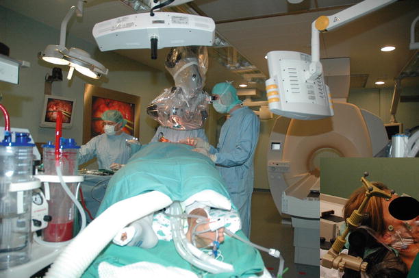
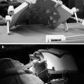
Fig. 35.5
The Kiel set-up. Patient’s head is in the “primary” surgical position. Picture is taken from position of the anesthesiologist. Ceiling-mounted navigation system in the foreground. For imaging the table is rotated, the table top connected to the MR-system and the patient moved to the scanner. Inlay shows the DRF attached to the Mayfield clamp
Our “primary” microsurgical site is outside the 5 G line, where conventional ferro-magnetic tools and equipment (e.g. microscope, ultrasonic aspirator, bipolar coagulation and cortical stimulation) can be used without limitations. A ceiling-mounted navigation system (BrainLab VectorVision) allows conventional neuronavigation with preoperative and updated navigation with intraoperatively acquired images (Fig. 35.5). The rotating angiography table (modified Angio DIAGNOS 5 Syncra Tilt Patient Support, Philips Medical Systems) allows transfer between surgical and imaging site.
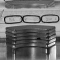
The head is fixed in a modified carbon-fibre, artefact-free Mayfield clamp (Promedics, Dusseldorf, Germany), rigidly connected to the table top. The dynamic reference frame (DRF) (current design by BrainLab) attaches to the Mayfield clamp. It has been designed in a modular fashion. The top portion holds the star, which has to be removed during scanning, while the bottom portion can remain in place. An interlocking design ensures precise repositioning of the removable upper portion.
For the initial phases of the surgery (planning, approach and initial debulking), a standard registration is performed, allowing the use of our ceiling-mounted navigation system.
The lesion is resected using microsurgical techniques. During the initial part of the resection, navigation systems can be useful to assist in the approach and identifying regions of interest. When reaching the tumour borders, the surgeon relies on the operating microscope for surface visualization. To further augment this surface visualization, we employ an additional technique, 5-ALA fluorescence guidance. Tumour cells with high metabolism, most commonly primary [5] and recurrent [52] gliomas, synthesize protoporphyrin IX (PPIX) from 5-aminolevulinic acid (administered orally prior to surgery), which accumulates intracellularly. On exposure to violet-blue light, through the specially equipped operating microscope, PPIX fluoresces bright red. Non-timorous tissue without high concentrations of PPIX does not fluoresce and remains dark.
At the surgeon’s discretion intraoperative MRI is acquired. The top portion of the modular DRF is removed (Fig. 35.6), the surgical site draped in a sterile fashion and the patient positioned within the scanner. Draping, transfer and preparation take about 3–5 min. The imaging protocol is prescribed by the surgeon according to the image characteristics of the lesion.
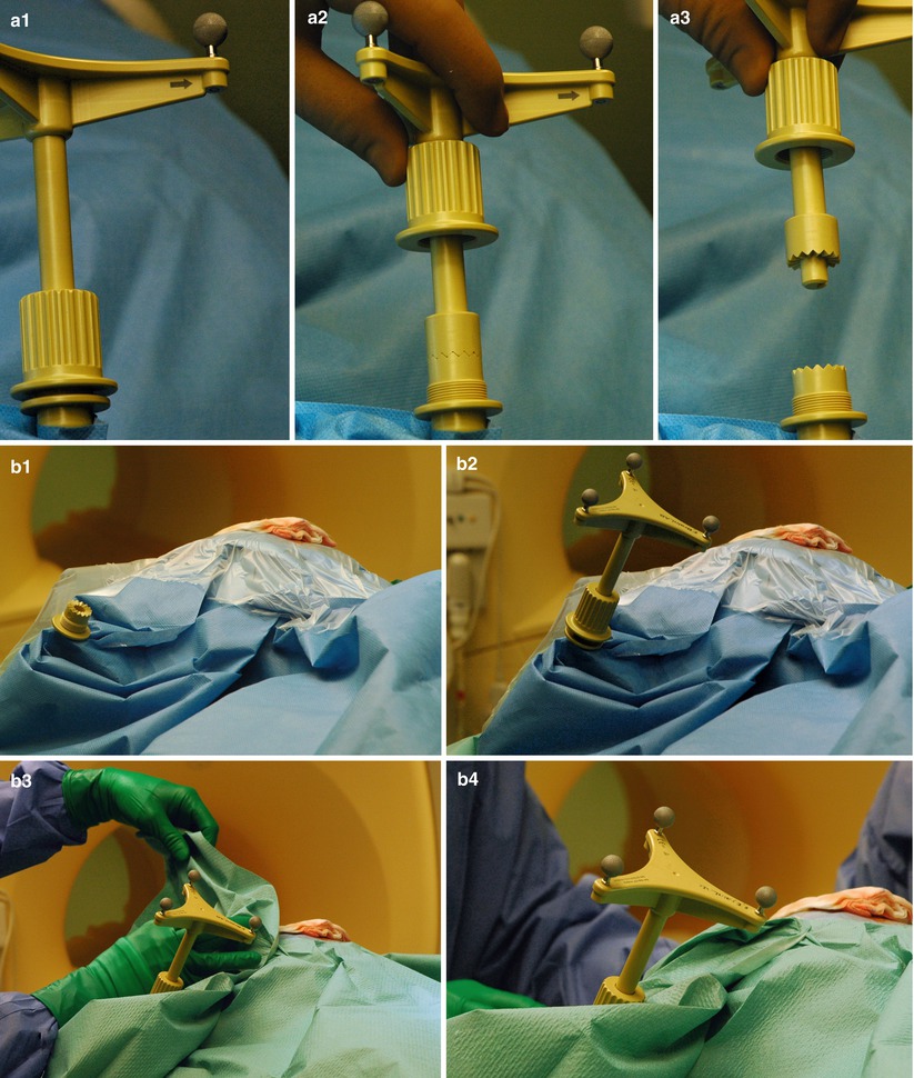
Fig. 35.6


Custom-made interlocking mechanism to attach the dynamic reference frame (DRF) for updated navigation. (a1–a3) For scanning the DRF is removed. The bottom portion remains rigidly attached to the Mayfield clamp. (b) Reattaching the DRF after scanning. (b1–b2) Additional coverings have been removed, unveiling the original drapes. A notch ensures the correct relocation of the top portion. (b3–b4) New sterile draping on top of the previous layer
Related posts:
Stay updated, free articles. Join our Telegram channel
Full access? Get Clinical Tree
