Fig. 19.1
Classification of breast imaging artifacts
19.3 Artifacts and Pitfalls in Mammography
19.3.1 Artifacts in Analog Mammography
Artifacts appear as either lighter (minus) or darker (plus) densities and as lines, bright specks, or blotches, may be caused by equipment or inadequate technique, or may be related to the patient (Berg et al. 2006a).
19.3.1.1 Film-Related Artifacts
Analog mammography involves the use of hard copy films and, hence, is associated with related artifacts due to technical errors in processing, film handling, and storage (Minigh 2009).
Film Processing Artifacts
Film processing is the major source of artifacts in analog mammography. Roller marks cause plus density parallel lines that lie perpendicular to the film travel. Delay streaks appear as plus density deposits of developer. Guide shoe marks are seen as plus or minus density lines parallel to the direction of film travel. Wet pressure produces plus density blotched artifacts from the rough surface of the rollers or uneven collections of developer. Too dark or too light films are caused by improper developer temperature or replenishment, improper fixer replenishment, or faulty film batch.
Film Handling Artifacts
Film handling is the second common source of artifacts. Dust prevents light from exposing film and may cause artifacts that resemble calcifications. Fingerprints may give plus and minus density artifacts, and minus densities may also mimic calcifications. Foreign bodies on the screen (e.g., pencil marks, fingernail polish, cleaning tissues, or chemicals) appear as minus density linear or mass-like artifacts. The artifacts resulting from stains and blotches may mimic a mass, occurring either before or after exposure. Scratches appear as sharply defined, linear, or irregular defects in the emulsion. Static electricity is recognizable as jagged lines or starlike plus densities.
Film Storage Artifacts
Cassette and film storage-related artifacts may occur. Improper film storage may result in film fogging which is caused by inadvertent exposure to a radiation source. A plus density artifact may be caused by light leak in a cracked cassette, damaged safelight filters in darkroom, upside-down film artifacts loaded in a cassette, or a cassette placed upside down in a Bucky grid.
Remedies for Analog Mammography Artifacts
Although analog mammography has been largely replaced by digital mammography, proper techniques and care are necessary in processing, handling, and storing the analog films to reduce the artifacts, keeping in mind the various causes as potential source of errors.
19.3.1.2 Equipment-Related Artifacts
These refer to mammography machine-related artifacts. These artifacts may be due to incorrect collimation, incomplete grid motion, Bucky failure, and compression system failure (Ikeda 2004). Remedies for prevention of these artifacts include mandatory regular quality control tests of the equipment. Equipment-related errors need to be detected and fixed by the service engineers. Identifying the sources of the artifacts often requires investigation with the phantoms.
19.3.1.3 Patient-Related Artifacts
Various materials located in or on patients may cause artifacts, e.g., deodorants, talc powder, clothing, tattoos, pacemaker, or foreign bodies (charm needles). Motion artifacts are caused by patient breathing and pulling. Poor positioning artifacts may be due to patient-derived artifacts such as hair, chin, nose, axillary–thoracic skinfold, and superimposition of the belly fold. Achieving an optimal mammographic image requires full patient cooperation. Patient-related artifacts, positioning as well as motion artifacts, occur more frequently in older age group. The aged loose skin is easily trapped in the compression paddle, causing the skinfold artifact. A poor or noncooperative patient who has difficulty in understanding is often unable to follow instructions that are required to attain appropriate position. Poorly mobile or wheelchair-bound patients are often not able to achieve and maintain adequate position, which leads to the positioning artifacts and artifacts caused by breast motion, uncontrollable breathing, and insufficient compression. Remedies for patient-related artifacts include reduction of patient motion by optimizing patient’s comfort and careful explanation which helps alleviate the anxiety of examination and may improve their cooperation.
19.3.2 Artifacts in Digital Mammography
19.3.2.1 Equipment-Related Artifacts
Full-field digital mammography (FFDM) is a new type of mammographic equipment which uses digital technology and X-rays to acquire and store images of the breasts (Pisano 2004). Computed radiography involves use of cassettes with photostimulable phosphor screens to record images which are scanned with a reader device in the workstation to produce a soft copy image. Digital radiography uses flat plane detectors for image acquisition. The equipment-related artifacts that occur in analog mammography can occur in digital mammography (Ikeda 2004; Lewin et al. 2004; Rothenberg et al. 2004; Bloomquist et al. 2006; Yaffe et al. 2006). Detector miscalibration artifacts are the most common artifacts in digital mammography. Fixed digital detector systems use calibration or gain correction to remove differences in sensitivity and nonuniformities of the X-rays. Sometimes, the calibration may cause persistent artifacts. Recalibration of the gain correction will remove persistent artifacts. If recalibration is made too soon after the exposure, a ghosting artifact can be introduced in form of lighter or darker areas on image. This remains and will appear on each subsequent image.
Filtration artifacts occur as mottled background across the entire image. Bad pixel artifact is seen as a white or black isolated dot. Several bad pixels in the group can cause appearance of black or white cluster artifacts. A column or row of bad pixels would introduce a line artifact. Improper collimation and improper detector alignment or damaged detector will cause black or white bands at the margins of the detector. Pre- or post-processing algorithm artifacts can occur. Dust artifacts may be seen as minus density specks on every image. The dust can the collect on top of the digital detector, breast support tray, and compressing paddle, mirror, or filter. Grid artifacts appear similar to those seen in analog mammography.
19.3.2.2 Patient-Related Artifacts
Patient-related artifacts are similar to those that occur in analog mammography and have an increased frequency in older group of women. Positioning artifacts such as belly fold (Fig. 19.2), chest skinfold (Fig. 19.3), inferior skinfold artifact (Fig. 19.4a, b), and chin artifact (Fig. 19.5) are more common phenomena in this age group as the loose skin is easier to be trapped in the compression paddle. Motion artifacts are caused by breathing or movement during acquisition. Foreign material artifacts may be due to deodorant/talc powder (Fig. 19.6), clothing tattoos, free silicone injection, and charm needles (Fig. 19.7). Patients with difficulty in understanding instructions and who are poorly mobile or wheelchair bound may not be able to stay in the required position and cooperate, which lead to considerable patient-related artifacts. The blurring caused by breast motion appears most commonly because of uncontrollable motion of breathing.
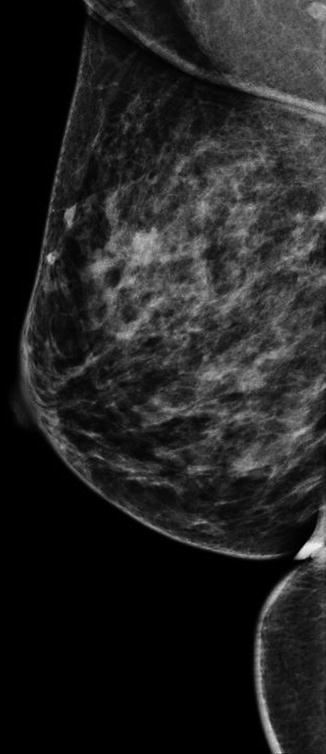
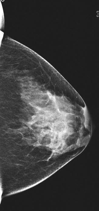
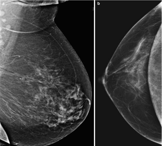
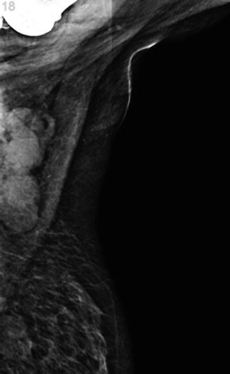
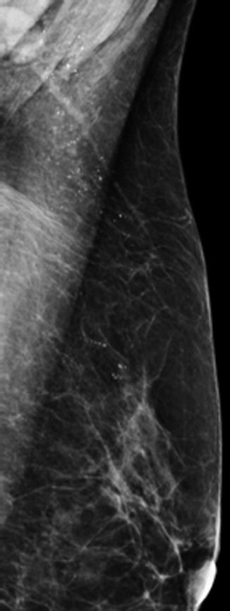
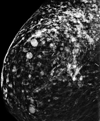
Fig. 19.2
Mammogram (MLO view) shows a belly fold at the inferior aspect of the breast and an axillary skinfold
Fig. 19.3
Mammogram (CC view) shows skinfold artifacts at the lateral and medial aspects of this projection
Fig. 19.4
Mammograms show a skinfold artifact at the inferior aspect of the breast on (a) MLO and (b) CC views
Fig. 19.5
Mammogram (MLO view) shows chin artifact at the superior aspect of the image
Fig. 19.6
Mammogram (MLO view) shows deodorant/talc powder artifacts mimicking microcalcifications in the axilla
Fig. 19.7
Mammogram (CC view) shows scattered rounded artifacts due to free silicone injection and dense linear artifacts from metallic charm needle
19.3.2.3 Other Artifacts
Other artifacts can be related to either laser printers or to image display monitors. Laser printer artifacts can be seen as horizontal or vertical lines or streaks, as a crisscrossed background, or as too light or too dark images. Image display monitor artifacts can occur as areas of nonuniformities, lines, streaks, black and white dots, or non-matching images. These artifacts are easily prevented by regular service and quality control of equipment.
19.3.3 Mammogram Interpretation Pitfalls
There is the risk of false positives, with a recall rate varying widely between 6 and 18 %. Abnormalities that are visible on both views may not be of the same lesion. The distance of the lesion from the nipple should be checked. It should be the same on the line of a curved arc from the nipple in both standard views. An additional true lateral view may help if confirmation is needed. Satisfaction of finding a lesion in the breast should not stop one from a complete systematic survey of the mammograms, as other abnormalities, such as a smaller second lesion, a cluster of microcalcifications, an axillary abnormality, or a lesion in the other breast, may be missed.
The area of interest may not be included in the mammogram if it is too peripheral, too posterior, too high in the axillary tail, or hidden in a large breast. Additional extended views, spot compression views, or 3D digital tomosynthesis, if available, can be used for further evaluation. For large breasts, a small cassette instead of the spot view may be used to identify the lesion in the region of interest. A problematic asymmetric density may be evaluated by a spot view, true lateral view, or 3D digital tomosynthesis, if available. An apparent cluster of microcalcifications or intramammary mass on standard views may actually be dermal in location. Additional true lateral, rolled or tangential views can be obtained for clarification when this is suspected.
19.4 Artifacts and Pitfalls in Breast Ultrasound Imaging
Artifacts may arise from any physical, electrical, or technical reasons which can cause abnormal echogenicity or acoustic shadowing on US imaging.
19.4.1 Grayscale US Artifacts
Crystal dropout causes a focal image defect which extends from the skin surface downwards. Inappropriate dynamic range, which is ratio of highest to the lowest displayed amplitudes in decibels, with optimal values being 55–60 dB for the breast, leads to fewer shades of gray. This may reduce image details if it is too low, or a cyst may appear hypoechoic instead of anechoic, if it is too high. Improper gain settings influence the image: if it is too high, falsely produced internal echoes make a cyst appear solid (Fig. 19.8a, b); if it is too low, it makes solid masses appear cystic.
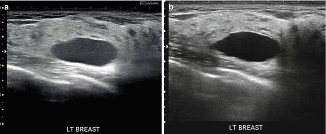
Fig. 19.8
(a) Breast US image shows improper gain setting artifact that is set too high, making the breast lesion appear solid. (b) Repeat US image with use of proper gain setting shows that the lesion is a simple cyst
Reverberation artifacts are series of bright echoes paralleling an interface with large differences in acoustic impedance. It may happen when the US beam on its way back to transducer is instead reflected on the wall of the lesion, insonate the tissue second time, the sound waves take longer to return to the transducer, or reflected sound beams are mapped deeper in tissue than they really are. This artifact is commonly seen with needles (Fig. 19.9), anterior wall of the cysts (Fig. 19.10), or silicone implants (Fig. 19.11).
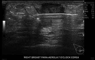
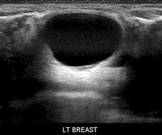
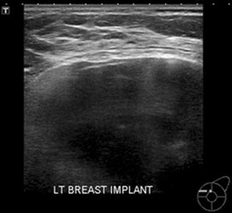
Fig. 19.9
Breast US image shows reverberation artifacts due to a biopsy needle
Fig. 19.10
Breast US image shows reverberation artifacts at the anterior wall of a cyst
Fig. 19.11
Breast US image shows echogenic noise and reverberation artifacts in a silicone implant
Ring-down artifacts are the echogenic bands perpendicular to the transducer, formed typically from air collection at the tip of the needle during biopsy. Specular reflection artifacts occur as bright linear echoes when sound bounces back to the transducer from the edge of the structure. Volume averaging artifact is due to superimposition of adjacent structures and can make the biopsy needle appear within the lesion, when in reality it is only near to the lesion (Fig. 19.12a, b). For correct interpretation of this artifact, scanning in the different axes needs to be done.
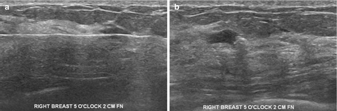
Fig. 19.12
(a) Breast US image shows volume averaging artifact making the biopsy needle appear within the lesion, when in reality it is only nearby. (b) Repeat US image in a different axis confirms that the needle is located outside the lesion
19.4.2 Color Doppler US Artifacts
Any movement will be mapped as an area of color. Respiratory motion, often uncontrollable in older or very ill patients, may cause great difficulty in the use of color Doppler US as an adjunctive tool of evaluation. Close cooperation of the patient is needed for the use of vocal fremitus (talking, humming, singing) for better distinction of a mass from normal tissue, to distinguish an isoechoic mass from normally perfused background tissue, or to distinguish a true mass from a fat lobule.
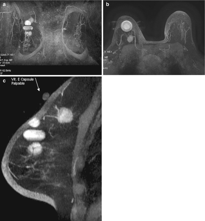
19.4.3 Silicone Implant-Related Artifacts
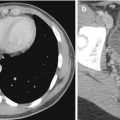
Snowstorm artifacts are caused by extracapsular silicone or by free silicone injection in the breast. They appear as a form of acoustic scatter or as markedly decreased acoustic transmission (Fig. 19.13a, b). Artificial increase of thickness and heights of implant appears because the sound waves travel slower in silicone. Echogenic noise is produced in the silicone implants due to reverberation artifacts of the invaginated fold of redundant implant shell or due to mixing fluids with gel caused by implant rupture (Fig. 19.14).
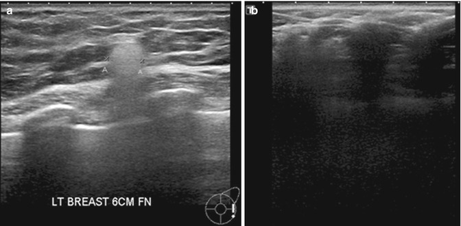
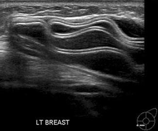
Fig. 19.13
(a) Breast US image shows a snowstorm artifact caused by extracapsular silicon. (b) Breast US image of another patient shows free silicone injection causing acoustic scatter with markedly decreased acoustic transmission
Fig. 19.14
Breast US image shows echogenic noise caused by reverberation artifacts of the invaginated fold of a ruptured implant capsule
19.4.4 Remedies for US Artifacts
In the recent decades, the generations of innovated automatic ultrasound machines have improved software for better imaging. Recent developments include B-mode enhancement tissue harmonic imaging (Szopinski et al. 2003), ApliPure compounding, and latest precision imaging by Toshiba™ which offer excellent clarification of images by reduction of equipment-related artifacts (Rosen and Soo 2001). Currently, the bigger responsibility in US artifacts are however patient related, with increased diagnostic limitation in the rapidly aging population, shared with artifacts due to insufficiently trained personnel applying inadequate techniques. A detailed patient medical history can be a big help to avoid misinterpretation of images.
19.4.5 Breast US Interpretation Pitfalls
Posterior enhancement (increased transmission) due to absorption of sound in a lesion is most pronounced in cysts which are benign. Malignancies such as invasive ductal carcinoma (IDC), metastatic nodule, or lymphoma can also exhibit posterior enhancement, which one should be aware of. Posterior shadowing (decreased transmission), considered a pronounced sign of malignancy (Cha et al. 2005), may also occur in benign lesions such as hyalinized fibroadenoma or focal stromal fibrosis. Confluence of free injected silicone into smaller or bigger foci with fibrotic reaction can mimic a mass lesion – silicoma (Fig. 19.15a, b). Calcifications may cause posterior shadowing, mimicking a malignant lesion which may be recognized by correlation with the mammogram (Fig. 19.16a, b). Acoustic shadowing behind the nipple suggestive of retroareolar mass may be resolved by changing the angle of insonation. Refractive edge shadowing around the curved edge of a mass can cause an apparent mass at the interface of the fat lobule. Increased pressure or/and change of angle as well as use of the color Doppler usually resolve the problem.
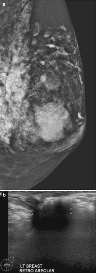
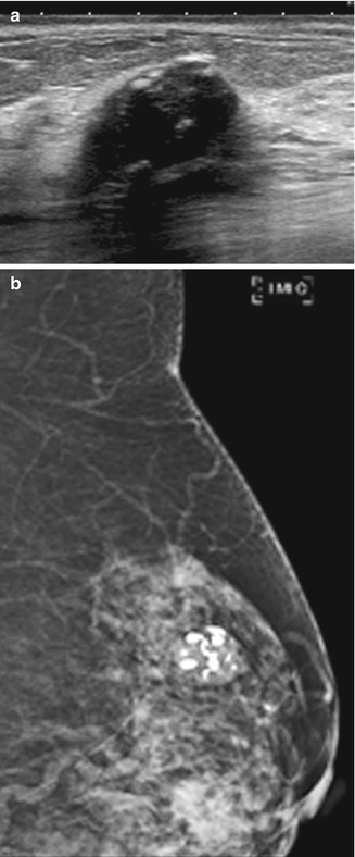
Fig. 19.15
(a) Mammogram (MLO view) shows a large mass in the retroareolar area. (b) Breast US image shows that the lesion is due to injected silicone
Fig. 19.16
(a) Breast US image shows a calcified fibroadenoma mimicking a malignant lesion. (b) Mammogram (MLO view) confirms the presence of a calcified fibroadenoma
19.5 Artifacts and Pitfalls in Breast MRI
MRI of the breast has come to the forefront as an ancillary tool in breast imaging to improve the detection and characterization of primary and recurrent breast cancers (Haydee Ojeda-Fournier et al. 2007). Apart from its use for detecting multifocality and multicentricity of breast cancer, MRI is also useful in differentiating between scar tissue and recurrent cancer. However, there are a number of artifacts and pitfalls that can potentially limit interpretation of the breast MR images by masking or simulating disease (Arena et al. 1995; Morris 2002). Artifacts are the features seen on breast MR images that do not faithfully correspond to actual anatomic structures leading to nondiagnostic and/or confounding findings. These artifacts may be related to patient, technique, or equipment (Coulthard and Potterton 2000) (Fig. 19.17).

Fig. 19.17
Classification of breast MRI artifacts
19.5.1 Patient-Related MRI Artifacts
19.5.1.1 Motion Artifacts
A significant artifact in MRI is due to motion and is often seen while imaging elderly patients. Even with an optimal prescribed protocol, any amount of motion can degrade image quality, or even render a study completely nondiagnostic. Artifacts from blood flow as well as cardiac, respiratory (Fig. 19.18), and patient motion all propagate in the phase-encoding direction, regardless of the direction of the motion. Motion results in blurring of moving tissues but also causes a structured noise pattern, resulting in “ghosting” of brighter moving tissues in the phase-encoding direction (Pusey et al. 1986; Rausch and Hendrick 2006). Motion artifacts can be due to physiologic motion and non-physiologic motion.
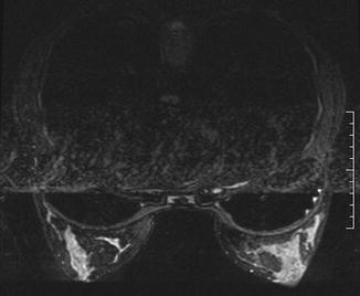
Fig. 19.18
Axial T2-W MR image of the breasts shows artifacts due to breathing and cardiac pulsation
Physiologic motion can be due to various causes. Pulsation of blood vessels may affect only a few image slices (Fig. 19.19). Periodic motion from vessel pulsation is specifically referred to as ghosting (Fig. 19.20). Generally, the pseudo-image appears as a hyperintense signal-replicated image of a normal structure in the phase-encoding direction. As motion always propagates in the phase-encoding direction, regardless of the direction of the motion, even minimal motion will cause misregistration on subtraction images that may limit their usefulness. The correct choice of the phase-encoding direction for breast MRI is left to right for axial images and superior to inferior for sagittal images. To eliminate pulsation artifacts, a saturation band can be placed over the moving structure using a standard sequence. The smearing from respiratory or cardiac motion occurs across the lateral chest rather than the breasts. If the phase-encoding direction is incorrectly chosen to be anterior to posterior with either axial or sagittal sequences, smearing from cardiac or respiratory motion can obscure large amounts of breast tissue. Periodic motion, such as vascular pulsation, results in ghosting occurring at regular intervals in the phase-encoding direction. Ghosting is a form of phase-encoding artifact (Morris 2002; Harvey et al. 2007). Reducing the repetition time may help reduce ghosting so that it is not propagated throughout the entire image, but doing so is often impractical in breast MRI.
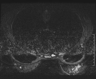
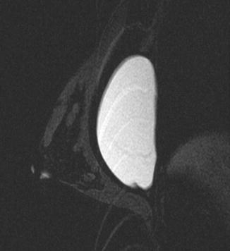
Fig. 19.19
Axial T2-W MR image of the breasts shows vascular pulsation artifact. This physiological motion artifact causes image distortion
Fig. 19.20
Sagittal T2-W MR image shows ghosting artifact with breast implant causing misregistration
Non-physiological motion is due to patient movement during the scan and can lead to unsatisfactory images affecting the entire series (Coulthard and Potterton 2000). Claustrophobia and patient anxiety remain the major contributors of this artifact, which are more commonly encountered in the geriatric age group due to different grades of senility. Patient motion can be reduced by assuring optimum patient comfort. This can be obtained by explaining the study to the patient, reassuring the patient before the examination, appropriate positioning with comfortable arm and head rests, optimizing examination time, providing sedatives, using physical restraints (straps), providing earplugs and blankets, and communication with the patient throughout the study as and when required (Rausch and Hendrick 2006).
Misregistration artifact is a type of motion artifact specific to subtraction imaging used in interpretation of breast MR images. This artifact is encountered when there is movement between the pre- and post-contrast image data sets to be subtracted (i.e., contrast-enhanced T1-weighted and non-enhanced T1-weighted image subtraction image). Edge artifact is a term used to describe the color mapping artifact caused by subtle misregistration that occurs in computer-aided detection. This artifact is identified as a mass appearance in a single section of one plane, but reformatted multiplanar images demonstrate no mass. The edge of the fat–parenchyma interface is color mapped in a planar fashion.
19.5.1.2 Metallic Artifacts
Ferromagnetic metals (such as iron, nickel, cobalt) cause severe inhomogeneity in the magnetic field. Metallic objects, including biopsy clips, jewelry, snaps on clothing, or imaging equipment on or near the patient, can interfere with the main magnetic field, resulting in metallic artifacts. The metallic object is devoid of mobile protons and hence does not emit a MR signal. However, the induced fixed heterogeneities of the magnetic field cause additional artifacts around the metallic object, resulting in a local signal intensity void in the vicinity of the metal (Haydee Ojeda-Fournier et al. 2007), often with a surrounding area of high signal intensity and image distortion. Similar but less prominent effects are seen due to the varying magnetic susceptibility of different tissues, such as bone and soft tissue. The size of the susceptibility artifact is dependent on the size and composition of the metallic object.
Surgical clips (Fig. 19.21a–d) and percutaneous biopsy clips may cause considerable distortion. If extensive, the artifact could preclude diagnosis of local recurrence at the lumpectomy site. On the other hand, signal intensity void from percutaneous biopsy clips may help confirm the biopsy location (Genson et al. 2007). MRI is sensitive for detection of metallic susceptibility artifacts, even when no metal is perceptible at mammography, due to the deposition of tiny metal fragments from the core needle biopsy or from devices used during surgery (Finder et al. 1998; Haigh et al. 2000a; Genson et al. 2007).