The rapid evolution of devices in the diagnosis and treatment of cardiac disease poses a challenge to the imaging professional. Devices are often readily apparent on imaging, yet extrapolating their use from their appearance is not always straightforward. Understanding the expected appearance and function of cardiac devices is the first step to identifying clinically significant complications. Additionally, understanding the indications for cardiac devices can provide important clues to the patient’s underlying cardiac disease if such clues are not provided in the clinical history.
Intraaortic Balloon Pump
Background and Indications
The intraaortic balloon pump (IABP) or intraaortic counterpulsation balloon device is a 25-cm long inflatable balloon mounted along a catheter placed into the descending thoracic aorta through a transfemoral approach. Inflation of the balloon with carbon dioxide is coordinated with ventricular diastole to reduce left ventricular afterload and to augment coronary artery perfusion. This process both decreases the demand on cardiac function and increases myocardial oxygenation. This device is temporary and is usually indicated in the immediate postoperative setting after cardiac surgery or after an acute myocardial infarction until cardiac function has recovered. Other indications include cardiogenic shock, septic shock, and left ventricular failure.
Imaging
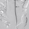
The tip of the IABP is ideally positioned approximately 3 cm distal to the expected location of the left subclavian artery in the descending thoracic aorta ( Fig. 18-1 ). A radiopaque marker indicates the tip of the balloon pump. The position of this tip relative to the aortic knob (radiographic landmark representing the confluence of the aortic arch, left subclavian artery, and proximal descending thoracic aorta) is typically taken as a surrogate marker for the position of the left subclavian artery origin. Positioning the balloon too near the ostium of the left subclavian artery may predispose the patient to embolism to the brain. Positioning the balloon too distal in the descending thoracic aorta risks transient occlusion of the superior mesenteric artery or renal arteries and subsequent ischemia or embolization.

Complications
The most common complications of IABP are vascular, including arterial perforation, dissection, visceral and limb ischemia, and peripheral embolization. Limb ischemia occurs in anywhere from 14% to 45% of patients. An IABP is an independent predictor of cerebrovascular accident in patients after percutaneous coronary procedures. Hemorrhage and infection of the groin access site are additional risks of this device.
Impella
Background and Indications
The Impella Circulatory Support System (Abiomed, Inc., Danvers, Mass) is a percutaneously placed device inserted through the femoral artery and advanced across the left ventricular outflow tract to bypass left ventricular function. Once the device is in position, with the tip in the left ventricle, internal propellers siphon blood from the left ventricle to the aorta. This device is typically used for short-term hemodynamic support in the setting of left-sided heart failure.
Imaging
The Impella device is visible radiographically in the expected distribution of the left ventricular outflow tract and ascending aorta ( Fig. 18-2 ). The curled tip of the device is meant to lie within the left ventricle and the outlet area in the ascending aorta.

Tandemheart
Background and Indications
The TandemHeart (CardiacAssist, Inc., Pittsburgh) is a continuous flow pump that directs blood from the left atrium to the systemic circulation and thus bypasses left ventricular function. Blood from the left atrium is accessed by passing an inflow cannula from the inferior vena cava to the right atrium and across the interatrial septum. This blood is transmitted to the systemic circulation through the femoral arteries. This device is typically used for hemodynamic support in patients with cardiogenic shock and in patients requiring high-risk cardiac interventions who are not appropriate surgical candidates.
Imaging
The inflow cannula is visible on radiographs as it traversing the expected location of the interatrial septum ( Fig. 18-3 ). The outflow cannulas are visible within the femoral arteries. The pump is not often imaged, external to the patient, and usually positioned about the thigh.

Complications
Complications of TandemHeart use include access site bleeding and hematoma, as well as the need for postprocedure transfusion.
Ventricular Assist Devices
Background and Indications
Ventricular assist devices are implanted mechanical pump devices used to augment cardiac output in the setting of heart failure. These devices are typically used as a bridge to heart transplantation, by sustaining perfusion to other organs and helping to rehabilitate the patient before the surgical procedure. If the patient is not a candidate for heart transplantation, these devices may be the only treatment option. Types of ventricular assist devices include pulsatile and nonpulsatile extracorporeal devices, implantable devices, and the total artificial heart.
Implantable devices, the most common ventricular assist devices, are implanted in a preperitoneal pocket in the upper abdomen. This site is chosen for easy access in the case of bleeding and infection. The inflow conduit is connected to the left ventricular apex, thus diverting blood from the left ventricle to the device. The outflow conduit connects the device to the ascending aorta. The device contains internal valves to prevent reflux of blood back to the left ventricle, and an external power source drives forward blood flow. Whereas first-generation devices work by pulsatile pump (e.g., HeartMate, Novacor), second-generation devices use continuous flow. A newer design of ventricular assist device allows placement in the pericardial space, directly adjacent to the heart, above the diaphragm (HeartWare HVAD left ventricular assist device, HeartWare International, Inc., Framingham, Mass).
Imaging
On radiography, the mechanical device is easily identified, although often it is imaged only partially ( Fig. 18-4 ). The inflow conduit should project over the left ventricle, and the outflow conduit connecting to the ascending aorta is often not radiopaque. Computed tomography (CT) shows the device conduits and their insertion to the left ventricle and ascending aorta, although beam-hardening artifact may limit evaluation of the mechanical portions. The HeartWare HVAD left ventricular assist device is shown in Figure 18-4 , D .

Complications
Device complications are related to device function or device placement. The risk of thromboembolic events necessitates anticoagulation while the device is in place. Pleural bleeding and pericardial bleeding are additional complications, and they should be suspected if the cardiomediastinal contour suddenly changes or a large amount of pleural fluid suddenly accumulates. Hemoperitoneum and abscess formation are abdominal complications of device placement. Finally, device failure may lead to worsening heart failure symptoms and pulmonary edema.
Smaller patients may not be able to receive a ventricular assist device. If necessary, these devices may be positioned intraabdominally.
Heartnet
Background and Indications
The Paracor HeartNet (Paracor Medical, Inc., Sunnyvale, Calif) is an investigational elastic ventricular restraint device developed for patients with heart failure in whom standard therapy has failed. The device is composed of nitinol mesh and is implanted around the ventricles through a minithoracotomy. The elasticity of the device is expected to reduce wall stress and to allow reverse ventricular remodeling.
Imaging
On chest radiographs, the HeartNet device appears as wavy radiopaque mesh around the ventricles ( Fig. 18-5 ).

Complications
In a feasibility study of 21 patients with New York Heart Association functional class II or III heart failure, the device was successfully implanted in 20 patients. Atrial fibrillation occurred in 2 patients, and the 2 in-hospital deaths were not directly related to the device.
Cardiomems Heart Failure Pressure Measurement System
Background and Indications
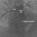
The CardioMEMS heart failure pressure measurement system (CardioMEMS, Inc., Atlanta) uses microelectromechanical systems (MEMS) technology to monitor pulmonary arterial pressure in patients with heart failure. The device, currently under investigation, consists of a radiopaque 15 mm × 3.5 mm wireless implantable sensor with nitinol anchoring loops ( Fig. 18-6 ), as well as an external electronics module. The electronics module powers the sensor through transmitted radiofrequency energy and receives data from the sensor.

Imaging
The CardioMEMS device (see Fig. 18-6 ) is usually implanted in the left pulmonary artery and is visible on chest radiographs. Depending on its orientation, it may be more visible on the lateral or the frontal view. The nitinol anchoring loops are visible on CT scans but are not easily seen on radiographs.
Complications
Potential complications of the CardioMEMS device include those related to the implantation of the wireless sensor (infection, bleeding, and thrombosis).
C-Pulse
Background and Indications
The C-Pulse (Sunshine Heart, Inc., Eden Prairie, Calif) device is a non–blood-contacting extraaortic implantable counterpulsation pump designed for the treatment of moderate to severe heart failure. The device is implanted using a full open sternotomy-hemisternotomy approach or using a limited right parasternal thoracotomy incision, leaving the sternum intact, and is then secured around the ascending aorta and pneumatically driven by an external system controller.
Imaging
In chest radiographs, the C-Pulse device is visible as radiolucency around the ascending aorta, in both the frontal and lateral views ( Fig. 18-7 ).

Complications
Device and drive-line infections have been reported with this device.
Left Ventricular Apicoaortic Conduit
Background and Indications
The apicoaortic conduit connects the left ventricle to the descending thoracic aorta. This conduit is typically used to bypass the aortic valve in patients with severe aortic stenosis when direct repair of the valve is precluded by contraindicated sternotomy (coronary bypass graft surgery) or severe ascending aortic calcification (porcelain ascending aorta). Alternatively, this device may be used when either the left ventricular outflow tract or the ascending aorta is hypoplastic, such as in congenital heart disease.
The conduit is connected between the left ventricular apex and the thoracic aorta, and an internal conduit valve prevents reflux of blood back to the left ventricle. Rarely, the outflow conduit is connected to a great vessel.
Imaging
The metallic ring of the apicoaortic conduit valve projects over the left lung base on frontal chest radiographs ( Fig. 18-8 ). On the lateral chest radiograph, the metallic ring projects over the middle mediastinum, usually posterior to the cardiac silhouette. The conduit itself, however, may not be visible radiographically. CT best defines the anastomotic sites and course of the conduit. Electrocardiogram (ECG) gating provides the optimum evaluation of the inflow (ventricular) conduit. Alternatively, magnetic resonance angiography may demonstrate flow through the graft, although dephasing artifact from the valve may limit evaluation. Echocardiography does not show the course of the graft or its aortic insertion. However, because blood flow should preferentially enter the low-resistance graft, significant forward flow through the left ventricular outflow tract on echocardiography may be an indirect sign of graft occlusion.