To lay the foundation for a discussion of thoracic cardiovascular disease, this chapter begins with an introductory review of anatomy on the chest radiograph. Central venous catheters are then used to illustrate vascular anatomy further and aid in recognition of malposition. Radiographic clues to abnormalities of the thoracic aorta and pulmonary vasculature are reviewed. Finally, pathologic appearances of the heart and pericardium are examined.
Normal Cardiovascular Anatomy on the Chest Radiograph
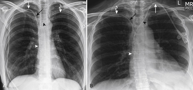
Normal posteroanterior (PA) and lateral chest radiographs, as well as relevant computed tomography (CT) correlations, are shown in Figure 11-1 . On the PA radiograph, the cardiovascular structures visible in the mediastinum are those that produce interfaces with the lungs. Along the right aspect of the cardiomediastinal silhouette, from superior to inferior, the margins of the right innominate vein, superior vena cava (SVC), right pulmonary artery, right atrial appendage, right atrium, and inferior vena cava (IVC) are visible. Along the left aspect of the cardiomediastinal silhouette, from superior to inferior, the left subclavian artery, aortic arch, aortopulmonary window, main and left pulmonary artery, and left ventricle are visible. Other cardiovascular structures and interfaces that can usually be seen on the radiograph include the azygoesophageal recess, azygos vein, and descending aorta.


On the lateral radiograph, the anterosuperior margin of the right ventricular wall and right ventricular outflow tract are visible adjacent to the retrosternal airspace. The IVC, lateral wall of the left ventricle, and aorta form interfaces with the lung. The right pulmonary artery is usually visible as an oval opacity anterior to the right upper lobe bronchus, whereas the left pulmonary artery can be seen coursing over the left upper lobe bronchus.
The normal locations of the cardiac valves can be approximated on radiography. On the lateral radiograph, the phrase “PAM watches TV” can be helpful in remembering the location of the valves with respect to each other. Because of the fibrous continuity of the aortic and mitral valves, these valves should always be in close proximity to each other.
Venous Anatomy and Normal and Malpositioned Central Venous Catheters
Chest radiographs are frequently obtained to confirm the position of central venous catheters and to exclude complications associated with line insertion. The course and tip position of the catheter allow the examiner to infer whether the vessel in which it travels is a specific vein or artery or whether it is extravascular in location.
Innominate, Subclavian, and Internal Jugular Veins
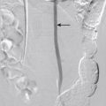
The right subclavian vein joins the right internal jugular vein to form the right innominate vein. Of these vessels, only the right lateral aspect of the innominate vein may be visible on the radiograph because an interface is created between the vein and the right upper lobe. In contrast, the left subclavian vein joins the left internal jugular vein, but the left innominate vein is not visible. The right and left innominate veins join to form the SVC. The relationships of these veins are demonstrated in Figure 11-2 . Peripherally inserted central catheters (PICCs) are commonly malpositioned in the internal jugular or left innominate vein ( Fig. 11-3 ).

The medial aspect of the subclavian veins should parallel the medial third of the clavicles, as should catheters in the subclavian veins. A catheter inserted into the right subclavian artery courses more medially into the mediastinum, with a less vertical course than expected from a catheter in the right subclavian vein. A catheter inserted into the left subclavian artery courses inferolaterally to the aortic arch instead of crossing the mediastinum in the left innominate vein, as expected ( Fig. 11-4 ). The subclavian vein courses between the first rib and the clavicle, anterior to the subclavian artery. Rarely, a catheter inserted into the subclavian vein can fracture as a result of repetitive compression of the catheter between the first rib and the clavicle, with migration of the distal fragment.

The internal jugular veins have a relatively vertical course, and catheters should also have a vertical orientation. A catheter inserted into the common carotid artery courses medially toward the aortic arch and is vertical in orientation ( Fig. 11-5 ).

Superior Vena Cava
The inferior margin of the SVC is at the SVC–right atrial junction or cavoatrial junction and is indicated by a convex bump that usually corresponds to the right atrial appendage. Because the right atrial appendage abuts the SVC to form this convex bump and they are in the same approximate coronal plane, this landmark is not usually affected by lordotic or antilordotic positioning. When visible, this convex bump is the most reliable marker of the cavoatrial junction, and the termination of the SVC is usually less than 1 cm inferior to this level.
A left-sided SVC occurs when the left superior cardinal vein caudal to the innominate vein fails to regress in embryologic development. The left SVC can be difficult to see on the chest radiograph, and it usually appears as a vertical interface projected over the aortic arch. The superior margin of the left SVC is formed by the left subclavian and jugular veins. The left SVC usually drains into the great cardiac vein in the left atrioventricular groove and then becomes the coronary sinus. In most cases, the left innominate vein persists between the two SVCs. Rarely, the right SVC regresses, and the left SVC is the only route for drainage of blood from the upper body. The presence of a left SVC can be inferred by the vertical course of a catheter along the left aspect of the mediastinum ( Fig. 11-6 ). Occasionally, an anomalous left innominate vein or an anomalous pulmonary vein can mimic a left SVC ( Fig. 11-7 ).


Inferior Vena Cava
The lateral margin of the suprahepatic IVC is visible on the frontal radiograph as a short line inferior to the right heart border. On the lateral radiograph, the posterior margin of the IVC is visible adjacent to the posteroinferior margin of the left ventricle.
Azygos Vein
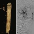
The azygos vein ascends in the posterior mediastinum along the right anterior aspect of the spine, drapes over the right mainstem bronchus, and drains into the posterior wall of the SVC. On a frontal radiograph, the normal azygos vein can be identified as an oval or round opacity in the right tracheobronchial angle and is usually less than 1 cm in maximal dimension. Enlargement of the azygos vein can be seen in the setting of volume overload or in any condition that impedes the return of blood to the heart through the SVC or IVC such as SVC obstruction or IVC thrombosis ( Fig. 11-8 ). Azygos continuation of an interrupted IVC ( Fig. 11-9 ) may be as large as and mistaken for a right aortic arch. A common normal variant is the presence of an azygos fissure ( Fig. 11-10 ). In this developmental variant, the azygos vein takes a more superior and lateral course through the lung before it crosses over the right mainstem bronchus and empties into the SVC. Malpositioned catheters in the azygos vein have a characteristic appearance on the frontal chest radiograph with a small, superiorly directed curve of the distal tip ( Fig. 11-11 ). On a lateral radiograph, a catheter in the SVC takes an approximate 90-degree turn posteriorly to enter the azygos vein.


Other Smaller Left-Sided Veins
The left second superior intercostal vein may be visible on the frontal chest radiograph as the vein courses anteriorly over the superolateral aspect of the aortic arch and appears as the so-called aortic nipple. If a catheter enters the left internal mammary vein and then the second superior intercostal vein, it can also have a classic appearance similar to a catheter in the azygos vein with a small, superiorly directed curve of the tip.
Occasionally, a left-sided catheter may not follow the course of the left innominate vein but takes a relatively vertical course. A left-sided SVC may be present, but malposition in a normal vein such as the left internal mammary vein ( Fig. 11-12 ) or left pericardiophrenic vein should also be considered, especially when the distal catheter does not course into the coronary sinus or right atrium. The left internal mammary vein is a tributary of the left innominate vein and runs immediately left of and posterior to the sternal body. On a lateral radiograph, the catheter is anterior to a catheter in a left SVC and also paralleling the sternum. Patients usually have two or three pericardiophrenic veins, and on the left side, these veins can outline the contour of the cardiomediastinal silhouette ( Fig. 11-13 ).


Extravascular Catheters and Complications
Catheters that do not conform to the expected course of a known artery or vein must be suspected to be extravascular in location ( Fig. 11-14 ). In addition to malposition, a high suspicion of complications of catheter insertion including pneumothorax and hemorrhage aids in detection. Mediastinal widening caused by hemorrhage may be easier to detect by comparison with prior radiographs.

Thoracic Aorta
The normal left aortic arch produces an oval opacity to the left of the spine at the level of T4 that is commonly referred to as the aortic knob. The descending aorta creates a vertically oriented linear interface with the left upper and lower lobes as it descends adjacent to the left aspect of the spine. On the frontal radiograph, the ascending aorta is usually not visible, except in the setting of older patients who have unfolding of the thoracic aorta, aortic dilatation, or, occasionally, aortic stenosis.
On the lateral radiograph, the anterior margin of the ascending aorta creates an interface with lung in the retrosternal space. The aortic arch and descending aorta are vaguely visible but are better delineated when patients have atherosclerosis and concomitant calcification.
Left Aortic Arch
The most common aortic arch variant is the common origin of the right innominate and left common carotid arteries, the so-called bovine arch (bovines do not actually have this aortic branching morphology). This aortic arch variant is typically not visible on radiography, although occasionally it can cause widening of a narrow superior mediastinum. The second most common aortic arch variant is independent origin of the left vertebral artery from the aortic arch, between the left common carotid artery and the left subclavian artery. The third most common aortic arch variant, the left aortic arch with retroesophageal aberrant right subclavian artery, occurs in approximately 1% of the population.
On the frontal radiograph, the aberrant right subclavian artery is occasionally visible as a mediastinal mass distorting the normal superior mediastinal contour ( Fig. 11-15 ). On the lateral radiograph, the aberrant subclavian artery (left or right) may appear as an oval opacity indenting the posterior aspect of the esophagus in the upper thorax. Rarely, the aberrant subclavian artery may cross the mediastinum between the esophagus and trachea or anterior to the trachea. If the origin of the aberrant subclavian artery is dilated, it is called a diverticulum of Kommerell.

If a predominantly right-sided superior mediastinal mass crosses the mediastinum and appears to arise from the aortic arch, the possibility of an aberrant right subclavian artery aneurysm should be considered ( Fig. 11-16 ).

Right Aortic Arch
If the normal left aortic arch is absent and a mass in the right paratracheal region is identified, the examiner should consider the possibility of a right aortic arch ( Fig. 11-17 ). The right aortic arch causes slight leftward deviation of the trachea and esophagus as it passes to the right. Then it descends along the right aspect of the spine, crosses to the left at the level of the right pulmonary artery, and continues its descent into the abdomen on the left side. Thus, the descending aortic interface is visible initially on the right in the upper mediastinum and then on the left in the inferior thorax.

Right aortic arch with mirror-branching morphology is a mirror image of the left aortic arch. The order of branches, from anterior to posterior, is as follows: left innominate artery, right common carotid artery, and right subclavian artery. Right aortic arch with aberrant left subclavian artery branches is as follows, from anterior to posterior: left common carotid artery, right common carotid artery, right subclavian artery, and left subclavian artery. In conjunction with the ligamentum arteriosum, the right aortic arch with aberrant left subclavian artery produces a vascular ring around the esophagus and can result in dysphagia, although most patients are asymptomatic. In contrast, the mirror right aortic arch has a ductus arteriosus that connects the left subclavian artery to the left pulmonary artery in front of the trachea and does not result in a vascular ring. More than 95% of patients with right aortic arch with mirror branching also have congenital heart disease. Fewer than 2% of patients with right aortic arch with aberrant left subclavian artery have congenital heart disease. Forty percent of patients with truncus arteriosus and 25% of patients with tetralogy of Fallot (TOF) have a right aortic arch with mirror-branching morphology.
Double Aortic Arch
Double aortic arch occurs when the ascending aorta divides into left and right aortic arches. This abnormality can be suspected on the frontal radiograph in patients with bilateral paratracheal masses indenting the lateral aspects of the trachea; these masses represent the aortic arches ( Fig. 11-18 ). The right aortic arch is usually larger and more superior than the left aortic arch. The arches join up posterior to the trachea and esophagus. On an esophagogram, the aortic arches that cause indentation of both sides of the contrast column can be seen. Classically, the more superior indentation results from the right aortic arch, whereas the more inferior indentation is caused by the left aortic arch. Thus, this complete vascular ring can also result in dysphagia or dyspnea.

Aortic Aneurysms
Fusiform aortic aneurysms are usually true aneurysms (i.e., all three layers of the vessel wall confine the aneurysm). Fusiform aortic aneurysms can be difficult to exclude on radiography unless the margins of the aorta are well visualized. In a young patient, visualization of the ascending aortic contour on the frontal radiograph should raise the possibility of an ascending aortic aneurysm or other aortic disease. The maximal diameters in the adult of the ascending aorta, aortic arch, and descending aorta are 4, 3, and 2 cm, respectively. An aneurysm is classically defined as present when the vessel is larger than 50% of its upper limit of normal. However, the ascending aorta is usually practically classified as aneurysmal when it is greater than 4.5 cm in maximal diameter and ectatic if it is between 4 and 4.5 cm. In addition to aortic dilatation, aortitis or inflammation of the aortic wall can cause tortuosity of the aorta.
Saccular aneurysms are usually pseudoaneurysms (i.e., not all three layers of the vessel wall surround the aneurysm). Saccular aneurysms can be identified as focal outpouchings of the aortic contour on radiography. Saccular aneurysms of the descending aorta ( Fig. 11-19 ) are usually easier to visualize than are those arising from the aortic arch. Saccular aneurysms may be secondary to infections (also referred to as mycotic aneurysms, although fungal organisms are not the only etiologic agent) ( Fig. 11-20 ) or trauma.


Acute aortic syndromes such as aortic dissection or intramural hematoma can cause nonspecific widening of the mediastinum, but this finding is not sensitive.
Aortic Coarctation
Aortic coarctation is a developmental anomaly that is thought to occur because of a small amount of tissue from the ductus arteriosum that migrates onto the descending aorta and constricts, as does the ductus arteriosus after birth. The coarctation usually occurs distal to the left subclavian artery origin, although occasionally it can be between the origin of the left common carotid artery and that of the left subclavian artery.
On the frontal radiograph, the constricted segment of the descending aorta appears as an indentation in the lateral interface of the descending aorta that produces the so-called figure 3 sign ( Fig. 11-21 ). Sixty percent of patients with coarctation have an abnormal radiographic contour of the aorta. The superior convexity, or top half of the 3, is the aorta proximal to the coarctation and may not be visible in children. The inferior convexity, or bottom half of the 3, is the aorta distal to the coarctation and represents poststenotic dilatation.

Related posts:

Stay updated, free articles. Join our Telegram channel

Full access? Get Clinical Tree


