Cardiovascular Magnetic Resonance Imaging Equipment
Mark Doyle
OVERVIEW
Cardiovascular magnetic resonance (CMR) utilizes a great deal of hardware. The major equipment systems for a CMR facility are as follows:
Magnet
Radio frequency (RF)
Scanner room
Patient monitoring
Scan controller
Peripheral equipment
MAGNETIC RESONANCE IMAGING SYSTEM
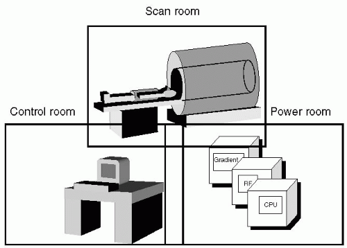
Currently, the CMR environment is organized around a suite of rooms, with one room devoted to the main system, one to power equipment, and one to scan control (see Fig. 2-1). Typically, other ancillary rooms that are common to any imaging facility are required and include patient reception, changing rooms, preparation, and interview areas. The heart of the magnetic resonance imaging (MRI) system is the main magnet. Commonly this is of a superconducting design, with the gradients and RF coils housed within it, with the whole assembly located in the scanner room. Accompanying the MRI unit are the power and control systems required to generate the imaging waveforms and to drive current through the gradient and RF systems. These are located in a power room, which has special cooling requirements to deal with the heat dissipation that is required. The third main area is devoted to scanner control and monitoring, and is usually referred to as the control room. Typically, the control room is arranged to provide a direct line of sight between the scanner operator and the patient in the scanner.
MAGNET
The most efficient magnet design is of the electromagnetic type, with the electrical windings wound on a cylindrical former. The coil windings are cooled to liquid helium temperature (4°K) allowing them to become superconducting, that is, current will continue to flow even after the power source is removed. To keep the magnet at 4°K requires isolating the system thermally. This is accomplished by surrounding the windings in a vacuum chamber and filling the cavity with liquid helium. Under normal operating conditions, helium will boil off and escape from the system. In order to conserve helium, a helium reliquefying system is typically integrated into the system; limiting “top-up” fills to greater than 1-year intervals. The chirping sound often heard in the scanner room is associated with the reliquification pump. In regions of the world where liquid helium cannot be easily obtained, it is possible to use nonsuperconducting electromagnets which are water-cooled. These require power when in operation, and typically the field strength is less than 1 T. Some design features can be introduced to offset the lower fields of these systems. In a horizontal cylindrical magnet, sensitivity to the received RF signal is physically in the transverse plane. The strongest signal reception can be achieved by using a Helmholtz or solenoidal coil design, but to be sensitive to this signal plane would require the patient to be positioned vertically in the scanner. However, such a design is not compatible with the human body lying horizontal along the direction of the field and the solution is to employ signal receivers of a less efficient design (see Fig. 2-2). Alternatively, a vertical magnetic field system allows the use of a solenoidal receiver coil (see Fig. 2-3). Vertical fields are typically found in magnets of the open design, and therefore these systems can harness the inherent superior sensitivity of the solenoidal design for the RF system. Therefore, due to the more efficient receiver coil design, a 0.7 T vertical bore magnet can perform similarly to a 1 T horizontal field system in terms of signal-to-noise ratio (SNR). Magnets are also available of a permanent design, which do not required power to generate a field, but typically their strength is limited to a maximum of 0.3 T.
 FIGURE 2-2 A cylindrical design of magnet with the patient lying horizontally is shown. The main direction of the field is indicated by the arrow and the radio frequency (RF) receiver coils that are arranged in the horizontal plane are sensitive to magnetization in the vertical (i.e., transverse) plane. Although this design is common, signal reception is suboptimal. |
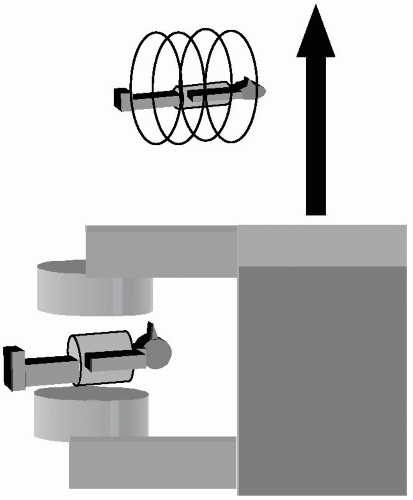 FIGURE 2-3 A vertical bore magnet system with the patient lying horizontally is shown. In this configuration a solenoidal receiver coil can be used, with sensitivity to radio frequency (RF) in the horizontal plane. This orientation of receiver coil is optimal, which, to some extent, may compensate for the lower field strength typical of this design. |
GRADIENT SYSTEM
Three strong electromagnetic gradients built into the scanner system constitute the primary gradients. They are activated when current is passed through them and are driven by powerful amplifiers. Typically, the gradients are designed to allow the maximum access for the patient, and in the case of the horizontal bore cylindrical system, the gradients are wound on a cylindrical former, which is located in the magnet bore. To appreciate the gradient design, it is important to note some salient properties of each gradient:
The magnetic field from each gradient varies in only one spatial direction.
The field from each gradient is applied to the body over a volume.
The direction of the field is always aligned with the main field direction.
The result of applying a gradient in this manner is that parallel planes within the body are established, each plane being at a uniform, but unique magnetic field strength (see Fig. 2-4). The field strength imposed on the body by a gradient is key to the imaging process. It is necessary to encode information in three orthogonal directions, which requires application of up to three imaging gradients. It should be noted that when two gradients are simultaneously applied, only a single gradient is realized, formed by the vector sum of the two component gradients. Therefore, two gradients applied simultaneously produce only a single gradient at an angle to the original two. In this case, the combined gradients simply change the orientation of the parallel planes of uniform magnetic field within the body. The primary gradients are very powerful, and generally require cooling by circulating chilled water thought the system. A water chiller located in the power room is required. Adequate removal of heat from the gradients allows them to perform at a high duty cycle. The power supplies for each of the electromagnetic gradients are housed in the power room. Usually the cables and coolant are passed through a “penetration panel” into the scanner system. The penetration panel filters out RF noise and signal that would otherwise contaminate images.
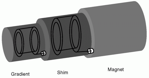 FIGURE 2-5 A telescoped view of three magnetic systems: main magnet, shim magnet (to correct for field inhomogeneities), and the primary gradients (X, Y, and Z). In the assembled system, the gradient and shim coils would be slid into the magnet in a symmetric manner. |
Stay updated, free articles. Join our Telegram channel

Full access? Get Clinical Tree


