Cardiovascular Magnetic Resonance Imaging Positioning
June Yamrozik
INTRODUCTION
The heart is an oblique structure in the body. Specific positioning techniques are needed to image this dynamic organ. This chapter will focus on the imaging planes of the heart. Step-by-step imaging techniques will be provided to perform these positions. The cardiac anatomic structures will also be shown on the resultant cardiac images. This will enable the novice technologist to become familiar with cardiac terminology, anatomy, and the cardiac planes of the heart.
IMAGING PLANES OF THE BODY
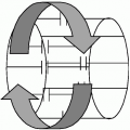
It is imperative to have a full understanding of the imaging planes for magnetic resonance imaging (MRI) positioning. The body is divided into three planes and a detailed description of each plane is as follows (see Fig. 4-1):
The Z plane, also known as transverse or axial plane, cuts the body from top to bottom or superior to inferior.
The Y plane, also known as the coronal plane cuts the body from front to back or anterior to posterior.
The X plane, also known as the sagittal plane cuts the body from right to left.
CARDIAC IMAGING PLANES
Two-Chamber or Vertical Long Axis (VLA) View
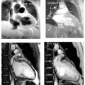
To acquire a two-chamber image (VLA), center parallel to the long axis of the left ventricle and left atrium from an axial or transverse breath-hold image (see Fig. 4-2A). To ensure accurate positioning always center from a breath-hold image. The resultant image will demonstrate the LV, left atrium, left atrial appendage, and mitral valve (MV) (see Fig. 4-2B).
Aliased Two-Chamber View
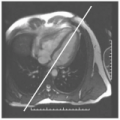
The field of view (FOV) that was selected was too small for this body habitus and fold over or wrap has marred this image (see Fig. 4-3).
Four-Chamber or Horizontal Long Axis (HLA) View
To acquire a four-chamber image (HLA), center parallel to the long axis of the two- chamber image (VLA) (see Fig. 4-4A).
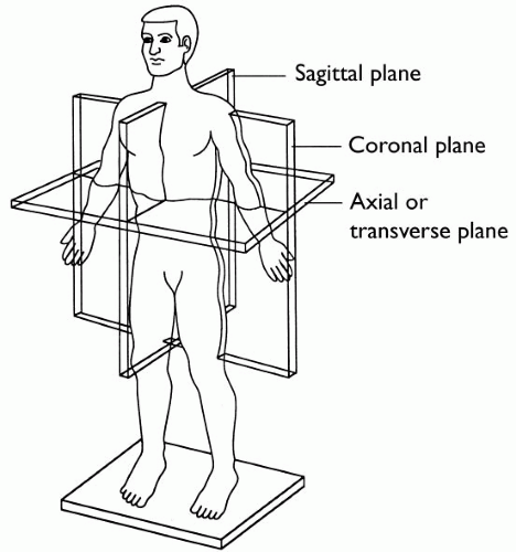 FIGURE 4-1 The planes of the body: Z = transverse or axial, divides the body superior to inferior or top to bottom, Y = coronal, divides the body anterior to posterior or front to back, X = sagittal, divides the body from right to left. |
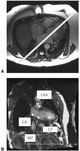 |
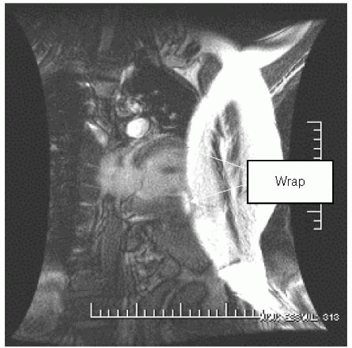 FIGURE 4-3 Wrap or aliasing producing a nondiagnostic two-chamber (VLA) image. This is produced by selecting an incorrect field of view (FOV). |
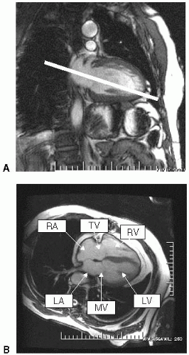 FIGURE 4-4 (A) Center parallel to the long axis of the left ventricle and left atrium from the 2 chamber (VLA) image. Do not center directly in the middle of the left ventricle but a little lower to avoid the aortic valve. (B) A properly positioned 4 chamber (HLA) will demonstrate the left ventricle (LV), right ventricle (RV), left atrium (LA), right atrium (RA), mitral valve (MV) and tricuspid valve (TV). |
 FIGURE 4-5 This image was centered a bit too superior resulting in having the aortic root in the image. It is wise to take more than one image to save time. |
The resultant image will demonstrate the right and left ventricle, the right and left atrium, mitral and tricuspid valve (see Fig. 4-4B).
Malpositioned Four-Chamber View
This image was positioned too superior on the two-chamber view. It is wise to set up two to three slices to get an accurate output image. The resultant image has the aortic root making it a five-chamber image (see Fig. 4-5).
Short Axis View
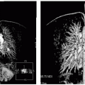
To acquire a short axis (SA) view, center perpendicular to the septum on the four-chamber view (HLA) (see Fig. 4-6A). The resultant image will demonstrate the left and right ventricle in a nice circular shape (see Fig. 4-6B).

Short Axis with Motion Artifact
This image demonstrates impaired image quality because the patient had difficulty holding their breath (see Fig. 4-7).
Additional Positioning to Acquire the Two- and Four-Chamber Images
There are additional ways to acquire the aforementioned images. A good mid-SA image that demonstrates the papillary muscles can be used to position the twoand four-chamber view. To acquire a four-chamber or HLA view, center in between the papillary muscles and at the base of the RV (see Fig. 4-8A). The resultant image known as the four-chamber or HLA view will demonstrate the right and left atrium, the RV and LV, and MV and tricuspid valve (see Fig. 4-8B).
The same SA image can be used to demonstrate the two-chamber view. Center perpendicular to the LV (see Fig. 4-9A) and the resultant image will demonstrate the LV, left atrium, left atrial appendage, and MV (see Fig. 4-9B).
It is wise to know both of these positioning methods, because sometimes for whatever reason (patient anatomy) one position might work better than the other. Therefore, make sure you know both ways of acquiring these images so it will not be difficult to deviate from your routine when one position is not working.
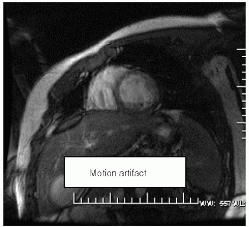 FIGURE 4-7 This patient had difficulty holding their breath causing motion on this image. To remedy this problem different parameters can be set on the machine. For instance, decrease field of view (FOV), or decrease matrix, or decrease number of excitations or try parallel imaging. |
 FIGURE 4-8 (A) Center in between the papillary muscles and at the base of the right ventricle (RV) from the short axis (SA) image to acquire a 4 chamber (HLA) image. (B) A properly positioned 4 chamber (HLA) will demonstrate the left ventricle (LV), right ventricle (RV), left atrium (LA), right atrium (RA) ,mitral valve (MV) and tricuspid valve (TV). |
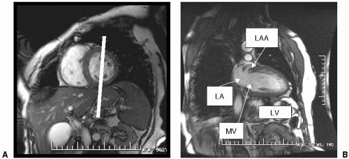 FIGURE 4-9 (A) Center perpendicular to the mid left ventricle from the SA view. (B) A properly positioned 2 chamber (VLA) image will demonstrate the left ventricle (LV
Get Clinical Tree app for offline access
Related posts:Stay updated, free articles. Join our Telegram channel
Full access? Get Clinical Tree


|