Cardiovascular Magnetic Resonance Imaging Protocols
June Yamrozik
This chapter discusses imaging protocols. Different protocols vary from institution to institution; so let this serve as a guideline to assist cardiac imaging. The cardiac magnetic resonance imaging (MRI) technologist will learn the proper sequences and positions for specific examinations.
OVERVIEW
Positioning
Two-Chamber or Vertical Long Axis View
To acquire a two-chamber view (vertical long axis [VLA]), center parallel to the long axis of the left ventricle (LV) on an axial or transverse breath-hold (BH) image (see Fig. 5-1A). To ensure accurate positioning always center from a BH image. The resultant image will demonstrate the LV, left atrium, left atrial appendage (LAA), and mitral valve (MV) (see Fig. 5-1B).
Four-Chamber or Horizontal Long Axis View
To acquire a four-chamber view (horizontal long axis [HLA]), center parallel to the long axis of the two-chamber view (VLA) (see Fig. 5-2A). Amid short axis (SA) slice that shows the papillary muscles can also be used (see Fig. 5-2B). The resultant image will demonstrate the right and left atrium, right ventricle (RV) and LV and MV and tricuspid valve (see Fig. 5-2C).
Three-Chamber View
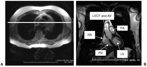
Center parallel to the long axis of the LV and aorta as shown on the left ventricular outflow track (LVOT[coronal view]) (see Fig. 5-3A). This image can also be acquired using a basal SA image that has the aortic valve (AV) captured on the image. Center parallel to the aortic root as demonstrated on an SA image (see Fig. 5-3B). Both positions will demonstrate the AV, MV, LV, and a portion of the RV (see Fig. 5-3C). Become familiar with both of these positioning techniques because sometimes one might work better than the other.
CARDIOVASCULAR MAGNETIC RESONANCE PROTOCOLS
Two to three of the images shown earlier are performed on all of our cardiac protocols. These views enable the physician to get a sufficient display of heart function. These sequences are considered routine at our facility.
Double inversion recovery-spin echo (DIR-SE) (black blood) non-breath-hold (NBH) transverse (axial) from the pulmonary artery (PA) to the base of the heart for morphology and diameter of vessels are also routine at our imaging modality. With no further ado, let us proceed to cardiovascular magnetic resonance (CMR) protocols.
CARDIOVASCULAR MAGNETIC RESONANCE IMAGING PROTOCOLS
Arch Cardiovascular Magnetic Resonance Imaging Protocol
A patient suffering from the following indications is most likely to be scheduled for an arch MRI/magnetic resonance angiography (MRA):
Dissection
Coarctation
Aneurysm
Marfan disease
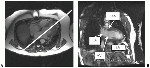 FIGURE 5-1 A: Center parallel to the long axis of the left ventricle and left atrium from a transverse or axial breath-hold image. B: A properly positioned two-chamber (vertical long axis [VLA]) image will demonstrate the left ventricle (LV), left atrium (LA) left atrial appendage (LAA) and mitral valve (MV). |
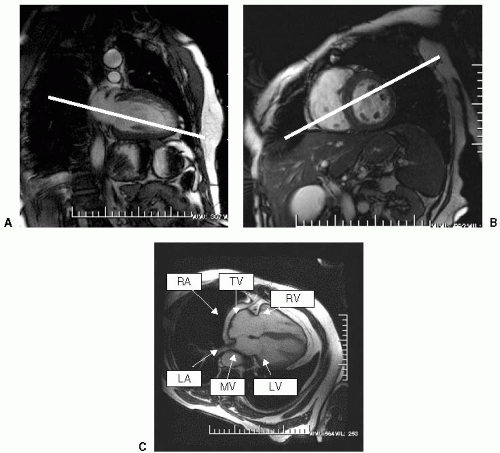 FIGURE 5-2 A: Center parallel to the long axis of the left ventricle and left atrium from the two-chamber (vertical long axis [VLA]) image. Do not center directly in the middle of the left ventricle but a little lower to avoid the aortic root. B: Center in between the papillary muscles and at the base of the right ventricle from the short axis (SA) image to acquire a four-chamber ([HLA]) image. C: A properly positioned four-chamber (HLA) will demonstrate the left ventricle (LV), right ventricle (RV), left atrium (LA), right atrium (RA), mitral valve (MV) and tricuspid valve (TV). |
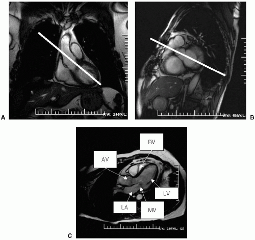 FIGURE 5-3 A: To acquire a three-chamber image, center parallel to the long axis of the left ventricle (LV) and aorta as shown in the (left ventricular outflow track [LVOT]) coronal view. B: Another way to acquire a three-chamber is to center parallel to the aortic root as shown on the basal short axis (SA) image. C: Both positions will demonstrate the aortic valve (AV), mitral valve (MV), LV and a portion of the right ventricle (RV). |
Protocol Set Up
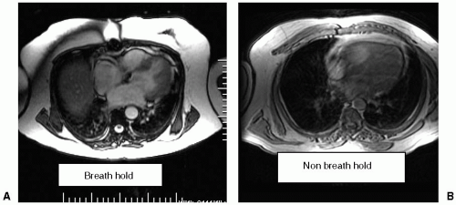
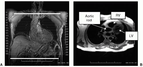
A three-plane (Z transverse, Y coronal, X sagittal) BH localizer scout is performed to ensure that the patient is properly positioned on the cardiac coil. The scout images should look as shown in Fig. 5-4A-C. A BH transverse (axial) scout image is then used to set up for the two-chamber images. Please look at Fig. 5-5A, B.
Sequences Performed
White blood imaging
Demonstrates heart function
Always center from a BH image (see Fig. 5-6A-C)
DIR-SE transverse (axial) NBH imaging
Start at the level of the apices of the lung and terminate at the renal arteries
DIR-SE
Black blood (see Fig. 5-7A, B)
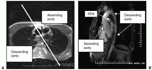
Center parallel to the ascending and descending aorta from a transverse (axial) BH image (see Fig. 5-8A)
Aortic arch seen in a candy-cane view (see Fig. 5-8B)
White blood sequence
This image is done to look for the following:
Coarctation
Dissection
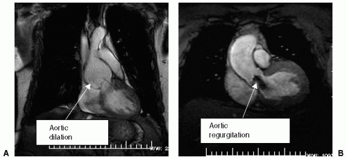
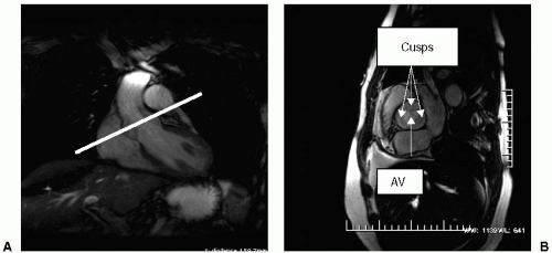
Center perpendicular to the aorta from a BH transverse (axial) image (see Fig. 5-9A, B)
This image is done to look for the following:
Aortic dilatation
Aortic regurgitation
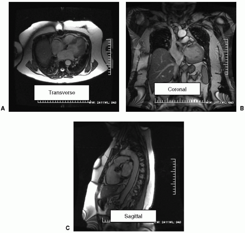
FIGURE 5-4 A-C: The signal intensity is in the heart area representing proper positioning of the patient and coil placement. Each image is a breath-hold which will produce consistent output images.
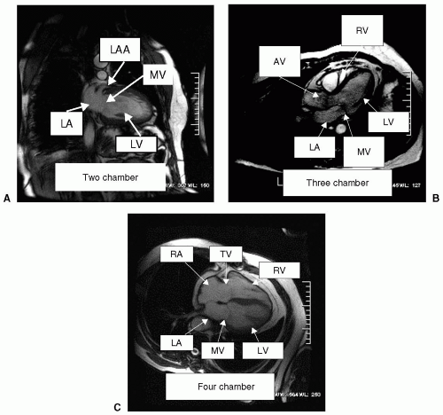
FIGURE 5-6 A-C: Routine imaging at our facility; two-, three- and four-chamber images. The two-chamber (vertical long axis [VLA]) image will demonstrate the left ventricle (LV), left atrium (LA) left atrial appendage (LAA) and mitral valve (MV). The four-chamber (horizontal long axis [HLA]) will demonstrate the left ventricle (LV), right ventricle (RV), left atrium (LA), right atrium (RA), mitral valve (MV) and tricuspid valve (TV). The three-chamber image will demonstrate the aortic valve (AV), mitral valve (MV), LV, and a portion of the RV.
Aortic aneurysm
Aortic stenosis (see Fig. 5-10A, B).
BH DIR paraxial is optional
It is imperative to perform aortic valve imaging if Marfan’s or coarctation is suspected
Bicuspid AV is critical to assess for these two diagnoses
Examples of AV (see Fig. 5-12A, B)
Perform a prerun parasagittal 3D volume centered parallel to the ascending and descending aorta from an axial (transverse) image
Coronal 3D volume may also be used depending on physician preference
10- to-20-second BH scan duration
This is done to ensure that the proper field of view (FOV) is used to accommodate the structure of the heart (see Fig. 5-13A, B).
Timing test run (GE)
Various methods can be performed, as follows:
Bolus tracking
Smart prep
Fluoroscopy
Basic timing to a parasagittal image will be discussed
This method has been found to be most accurate at our institution

Stay updated, free articles. Join our Telegram channel

Full access? Get Clinical Tree


