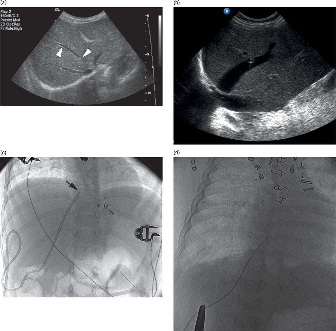
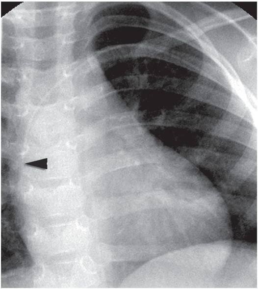
This transesophageal echocardiogram demonstrates the structures that form the inferior margin of the superior vena cava (svc) in the right atrium (ra), including the crista dividens (remnant of the septum secundum) in the intra-atrial septum (posterior arrowhead), and the crista terminalis (anterior arrowhead). Image courtesy of Meryl Cohen, MD.
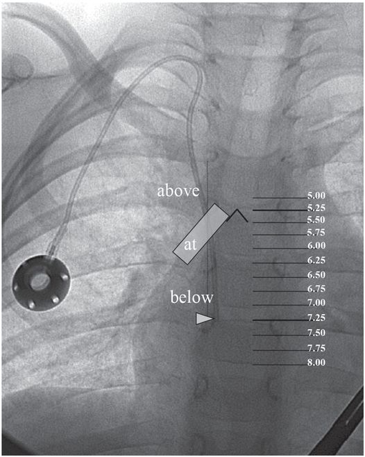
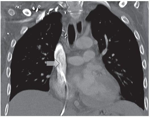
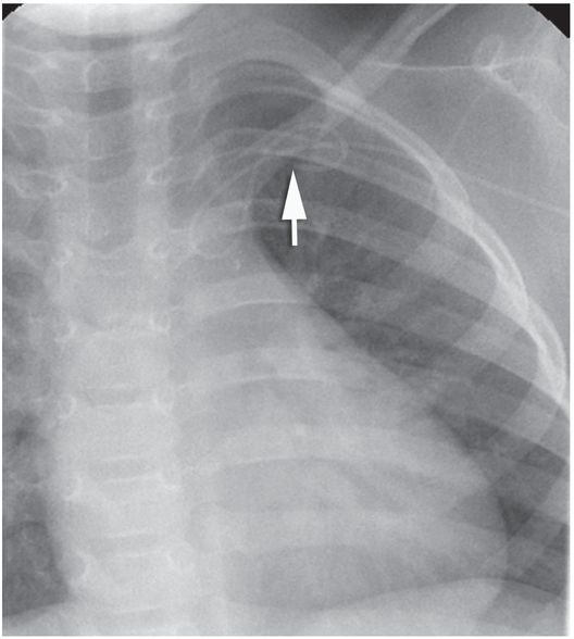
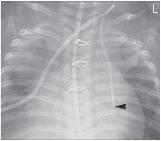
A right internal jugular indwelling venous port catheter tip is positioned with its tip (arrowhead) two vertebral bodies below the carina, below the right mainstem bronchus. Three-dimensional analysis of the chest CT obtained at the same time as this topogram confirmed this point to be precisely at the cavoatrial junction in this patient.
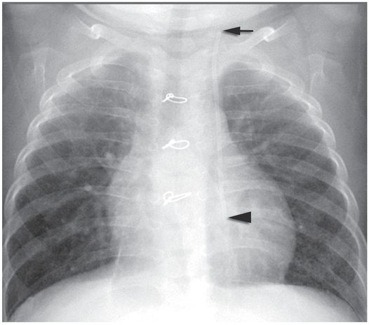
This region corresponds to a point two vertebral bodies below the carina on a posterior–anterior (PA) chest radiograph (Figure 2.1b), and not to the upper margin of the right cardiac silhouette. In fact, CVCs that seem to be located high in the right atrium by chest radiograph are often actually in the superior vena cava (SVC) and pose little risk of cardiac perforation. Catheter tip position in the region of the entrance to the right atrium helps assure that the catheter tip will float freely and more centrally within the vascular lumen, less prone to malposition through respiratory and other patient motion, fixation or occlusion against the lateral wall of the SVC, or vascular injury and perforation, especially for catheters entering from the left side.
Challenges may arise when preferred pathways are not accessible, due to venospasm, venous thrombosis or fibrosis, overlying scar, inflammation, burns, infection, or other factors. Prolonged attempts at a difficult site often show rapidly diminishing returns. In patients without a history of prior access, simply moving to the contralateral side or to an alternate preferred site is usually sufficient for success. This may require changing access devices as well, perhaps selecting jugular CVC insertion when venospasm prevents passage of a PICC, for example. Anticipation of such changes in plan is reflected in preprocedural discussions with referring physicians, patients, and parents, so the child leaves the interventional suite with adequate access despite unforeseen obstacles. In patients with a history of difficult access, more careful pathway planning becomes important.
Magnetic resonance angiography has been suggested for mapping potential pathways for central venous access in patients with a history of chronic deep venous thrombosis (DVT). However, it is in just those most challenging patients with extensive collateralization that MR angiography is least accurate. Ultrasonography (US) performed just prior to access frequently displays patent veins as well as obstacles to access such as intravascular thrombosis and anatomic variation. However, the limited field of view compared to CT or fluoroscopy makes it less useful for demonstrating collateral pathways. Once collaterals are identified, US can be used to guide needle insertion. In patients with a history of difficult access, it is sensible to perform contrast venography at the time vascular access is first obtained, even if initial access is achieved under US control. Even if a direct pathway (i.e., via named vessels) to the right atrium is not available, alternate pathways are often visualized.
These pathways may be quite complex (e.g., jugular → paravertebral → hemizygos → azygos → right atrium; Figure 2.2), and may require unusual methods to navigate as variously described in “Technical variations,” below. Procedures for access via some alternative pathways (e.g., translumbar (Figure 2.3) and transhepatic (Figure 2.4)) have been well described. Other alternate pathways, such as retroclavicular brachiocephalic access (Figure 2.5), are not well known and require advanced ultrasound guidance skills but offer very safe and durable access in patients with extensive central venous occlusions. In the end, one must weigh the needs of the patient against the time and cost of pursuing difficult access. For a relatively short course of antibiotics, serial peripheral angiocatheters might provide adequate access. For a line-dependent child, more novel, complex, and higher risk procedures may be warranted.
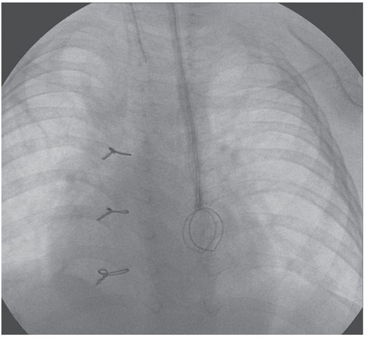
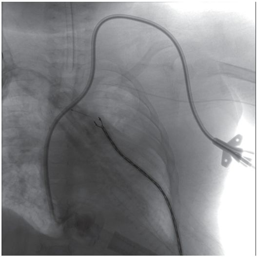
This child with chronic intestinal failure, dependent on parenteral nutrition, presented for central venous access insertion after therapy for a prior central line associated bloodstream infection. All conventional venous pathways above the diaphragm were occluded. This double lumen catheter was advanced over a wire that had been manipulated through a complex route from left jugular vein through the paravertebral vein, hemizygos vein, and azygos vein to the right atrium, where it was snared from a right transfemoral approach and exteriorized for stability. The central venous catheter could not be advanced beyond the azygos arch due to the tortuosity of the pathway, but provided adequate access until liver transplantation was performed.
A nine-year-old boy with multicystic dysplastic kidneys, after numerous venous procedures, had complete occlusion of all six conventional central venous pathways despite vigorous recanalization efforts.
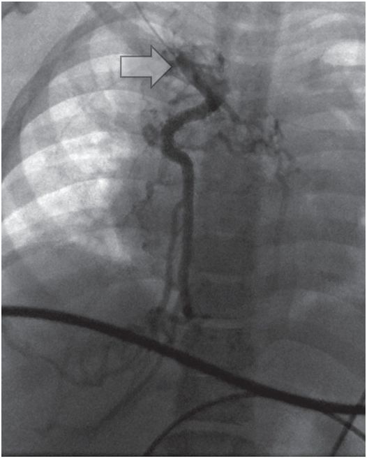
Venography from the junction (arrow) of the right internal jugular and subclavian veins demonstrates complete occlusion of the systemic veins and azygos arch with drainage below the diaphragm through azygos and hemizygos collaterals.
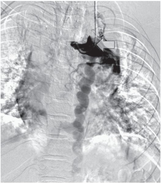
Venography from the contralateral side (arrow) shows complete occlusion of the left internal jugular, subclavian, and brachiocephalic veins with drainage below the diaphragm via hemizygos collaterals.
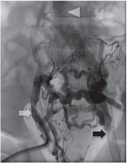
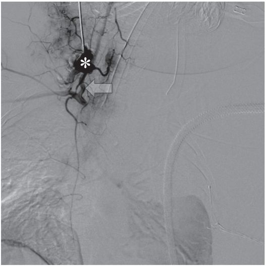
Contrast injection through the existing right external iliac hemodialysis catheter (white arrow) shows complete occlusion of the pelvic veins with reconstitution of the IVC (arrowhead) via somatic collaterals. A left femoral vein stent (black arrow), placed several years previously by interventional cardiology, is also completely occluded.
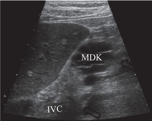
After pathway planning with three-dimensional rotational venographic reconstruction, the infrarenal inferior vena cava (IVC) was accessed under US guidance with a 15-cm 22-gauge Chiba needle (arrows), passing inferior to the kidney (MDK).
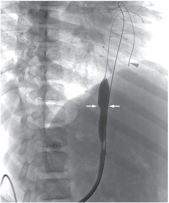
Secondary patency was retained after balloon disruption of a fibrin sheath (arrows) and catheter replacement over a superstiff guide wire. A second guide wire (arrowhead) was placed outside the sheath as a safety wire.
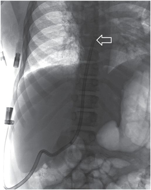
The tip (arrow) of the dialysis catheter is within the right atrium per Kidney Disease Outcomes Quality Initiative (KDOQI) guidelines. This pathway remained in use for hemodialysis over two years later.
A 17-year-old male with long-standing renal failure after liver transplantation requires a hemodialysis catheter. The IVC is occluded at the confluence of common iliac veins.
Contrast injection through a preexisting middle hepatic venous catheter shows complete occlusion of the brachiocephalic veins at the confluence, with a patent proximal SVC.
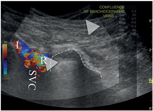
An overlay of two right retroclavicular coronal ultrasound images demonstrates color Doppler signal in the SVC, at the confluence of the right (R) and left (L) brachiocephalic veins. A 21-gauge Chiba needle (arrowheads) has been advanced from the base of the neck into the stump of the right brachiocephalic vein, just medial to the superior-medial pleural margin (dotted line).
Contrast is seen in one lumen of the tunneled right brachiocephalic vein. 14-Fr hemodialysis catheter inserted using the access shown in (b). A preexisting right pleural pigtail thoracostomy drain is also seen, unrelated to this procedure.
Peripherally inserted central catheter (PICC) insertion
Introduction
Silicone catheters were first introduced in 1961 by Stewart and Stanislow and have subsequently gained favor. Development of the silastic catheter and insertion techniques has helped make long-term indwelling catheter insertion one of the most commonly performed procedures in both the pediatric and adult populations. Peripherally inserted central catheters (PICCs), introduced for parenteral nutrition in neonates by Shaw, have been in use since the 1970s. These small-gauge silastic or polyurethane catheters are advanced through peripheral veins, usually of the upper arm or forearm, with the tip positioned centrally. Initially, these were passed through a short peel-away sheath preloaded over a single wall access needle, and passed blindly without a guide wire a predetermined distance calculated to place the tip in the mid- to distal-portion of the SVC. This method is still in use for bedside placement on the ward and in intensive care units. It is associated with a high rate of complication, including failed insertions and frequent malposition or non-central position.
Various methods have been used since to assure proper positioning, including radiographic and US guidance, and use of adjuncts such as intra-atrial EKG monitoring. Many institutions now find it cost-effective to stratify candidates for PICC insertion, assigning straightforward insertions to specially trained nurses, and reserving complicated patients for image-guided placement by an interventional radiologist. This again emphasizes the importance of coordination of vascular access services across the institution.
Indications
There is a general perception that nearly all patients will require a peripheral intravenous angiocatheter on admission to the hospital. This perception may delay consideration of PICC or CVC insertion in the substantial proportion of patients for whom prolonged therapy (greater than one to two weeks) can be anticipated on or prior to admission. For this reason, many children are subjected to the discomfort and increased complications associated with frequent replacement of peripheral angiocatheters, and end up with a PICC anyway. Since their introduction, their scope of use has been broadened considerably (Table 2.2).
| Temporary (non-tunneled) CVC (short-term access: <7 days) Urgent or emergent access Fluid and electrolyte resuscitation Antibiotic therapy Hemodialysis and apheresis |
| PICC (short- to long-term access: two weeks to >three months) Antibiotic therapy Hyperalimentation Fluid and electrolyte therapy Phlebotomy |
| Permanent (tunneled) CVC (intermediate- to long-term access: two weeks to >three months) Chemotherapy Hyperalimentation Antibiotics Blood product administration Fluid and electrolyte therapy Phlebotomy Chelation therapy Hemodialysis and apheresis |
| Indwelling port (long-term access, intermittent) Chemotherapy Hyperalimentation Blood product administration Fluid and electrolyte therapy |
Originally, PICCs were used predominantly as an alternative to serial peripheral angiocatheters, allowing safer administration of sclerosing medications, avoiding the need for frequent catheter replacement, and permitting substantial improvements in nutrient delivery and weight gain. PICCs are now also used as an effective alternative to tunneled central venous catheters in many applications. They are most commonly used in children to deliver long-term parenteral nutrition, but are also helpful for intermediate- to long-term access for delivery of chemotherapy, antibiotics, blood products, and fluids and electrolytes, as well as for patients who require frequent blood sampling.
Because children can receive care at home with a PICC in place, central venous access via a PICC line can allow them to be discharged earlier from tertiary care institutions to receive care closer to home, lowering the cost of care as well as the impact on the patient and family. PICC insertion with imaging guidance is safe and effective for patients of all ages and sizes, and is associated with a high rate of success and a low rate of infections and other complications.
Technique
Equipment
The selection of needles, catheters, guide wires, and other equipment varies considerably depending on the experience and preference of the interventionalist and the size, age, and condition of the patient (Table 2.3). In the pediatric age group a range of access needle sizes, catheter diameters, and lengths of single and double lumen catheters are needed (Figure 2.6).
| PICC Access needle angiocatheter (22–18 gauge) single wall needle Potts–Cournand needle Seldinger needle Peel-away sheath (3–5 French) Catheter (3–5 French) (single or double lumen) Guide wire (glide wire, Newton wire, mandril wire,” J” wire) Heparin (<10 kg = 1.5 ml 1:1,000, >10 kg = 3 ml 1:1,000) Suture (3–0 silk, 4–0 vicryl) Clear occlusive dressing |
| CVC Access needle single wall needle angiocatheter (22 gauge) Micropuncture kit Tapered vascular dilators Peel-away sheath (3.5 to 17 French) Tunneling device Scalpel Central line (single, double, or triple lumen) polyurethane (3 to 7 French) (length: 5, 8, 12, 15 cm) silastic (3 to 9 French) (length: tailored to patient size) apheresis (7 to 12 French; double lumen) dialysis (7 to 14 French; double lumen) Guide wire (Newton wire, “J” wire, glide wire, Amplatz Stiff® wire) Heparin (<10 kg = 1.5 ml 1:1,000, >10 kg = 3 ml 1:1,000) Suture (3–0 silk; 2–0, 3–0, 4–0 vicryl) Clear occlusive dressing |

3 French single lumen PICC (Cook Medical).

5 French dual lumen CT compatible PICC (Cook Medical).
The needle size selected for venipuncture depends on the child’s weight and size. A sheathed needle (angiocatheter) or a single wall needle is usually preferred. A Potts–Cournand or Seldinger single wall needle attached to a slip-tip saline syringe is occasionally helpful during fluoroscopically guided access to keep the operator’s hand out of the beam. We recommend an access needle thin enough to decrease risk of vasospasm but with a bore large enough to pass at least a 0.018-inch guide wire. For very small infants it is occasionally necessary to begin with a smaller needle and wire, exchanging for a larger dilator or peel-away sheath once access is achieved. Children weighing 10 to 20 kg are usually accessed with 20- or 22-gauge needle. Occasionally, in larger children, 19- or 18-gauge needles are used.
PICCs are available in a range of sizes (2 to 7 French as single lumen catheters, 3.5 to 7 French as double lumen catheters) constructed of polyurethane in fixed lengths or of silicone/silastic, tailored to the desired length during the procedure. Most clinical indications for PICC insertion in children may be satisfied with a 3 or 4 French single lumen catheter. If desired, the silicone PICC lines are made with cuffs and can be tunneled or connected to a port. They are non-tapered and have a high friction coefficient. Thus, they are best inserted through a peel-away sheath and are more difficult to insert over a guide wire than catheters constructed of other materials. In contrast, the polyurethane catheters are firmer, have larger lumens and greater flow rates relative to French size, and are easier to insert. Since they have tapered ends they do not require a peel-away sheath and travel over a guide wire with considerably less effort. Their stiffness may increase the risk of vascular perforation in certain applications.
Patient preparation
Informed consent for PICC insertion generally includes discussion of the technical aspects of line insertion, the differences between a CVC and PICC, the procedural risks, benefits and alternatives to PICC insertion. The lower risk of PICC insertion is stressed but the more common, adverse effects including local phlebitis, hematoma formation and infection, are noted. We find it helpful to draw a diagram of the proposed procedure to aid patient and parental understanding and answer questions. Because PICC insertion is never a certain outcome, especially in very sick or small children, we routinely prepare patients, parents, and referring clinicians for the possibility of CVC insertion as an alternative to abandoning or unduly protracting a difficult or unfeasible attempt at PICC insertion.
All children are kept NPO for at least six hours so that they can be safely sedated. The occasional child requiring general anesthesia (GA) will be prepared according to the anesthesiology department protocol as if the child were to go to the operating room. When possible, children not receiving GA may benefit from topically applied anesthesia (e.g., eutectic mixture of local anesthetic, or EMLA®, cream or J-tip) placed at likely access sites at least one hour prior to the planned procedure. Laboratory tests are seldom required prior to PICC insertion, unless there is a known or suspected bleeding diathesis, or other pertinent medical condition. In such cases, tests may include a CBC, platelet count, PT, PTT, and rarely a bleeding time. Even so, PICC insertion may be accomplished with due care even in patients with an uncorrectable coagulopathy if the indication warrants, although every effort is made to normalize coagulation. Similarly, with appropriate caution and image guidance PICC lines and perhaps even CVCs may be inserted in patients receiving concurrent anticoagulant therapy. Prophylactic antibiotics are not routinely given, even for children with heart disease, congenital or acquired immune deficiency, sepsis, or high risk for infectious complications, as they do not measurably decrease the catheter-related infection rate in these children, but may increase antibiotic resistance in the at-risk population.
Once in the room, the child is placed on the angiography table and lightly secured with Velcro straps to reduce motion and avoid falling. All children are monitored with pulse oximetry and an automated blood pressure device. A sensor for pulse oximetry is secured to a finger, toe, foot, or an earlobe. Leads are placed for cardiovascular monitoring. Reusable sensors are available for small babies. An intravenous line is started, if possible in the basilic or cephalic vein, or in the hand of the same arm where PICC placement is anticipated. Currently, venographic guidance for entry site selection is rarely used (Figure 2.7). Instead, US is almost exclusively used for entry site selection and real-time guidance of venipuncture. Although it is sometimes faster and easier to perform a standard venipuncture without imaging guidance at or just below the antecubital fossa with an angiocatheter to gain access into the venous system, the superficial access and location of the catheter at the crease of the elbow may increase the risk of “blown” veins, phlebitis, and mechanical injury to the catheter. We have found it preferable to access under US guidance in nearly all cases, in the upper arm above the antecubital fossa, where the deeper veins are more stable.
After cannulation of a collateral vein (arrow) in the arm of an 18-year-old woman with cystic fibrosis, injected contrast refluxes into the basilic vein. A hemostat tip is used to localize the basilic vein prior to venographically guided access. An elastic tourniquet (arrowheads) effaces the axillary vein.
A diagnostic venogram is not routinely performed prior to PICC insertion. We have found a venogram to be beneficial in the following situations: children who have had cut-downs; children who have had numerous venipunctures; those with a history of difficult or limited venous access; small children; and whenever there is difficulty maneuvering a catheter or guide wire into position. A venogram will show the venous anatomy and demonstrate the presence of collaterals, small, angulated connecting veins, and vasospasm.
Standard technique
There are variations in the order of steps, equipment, and monitoring used to place PICCs in various interventional practices (Table 2.4). In some practices, initial access is accomplished aseptically, with or without image guidance, according to the preference of the interventionalist. Our approach is to sedate or anesthetize the child, select the entry site, locally anesthetize the skin and subcutaneous tissue, and to use image guidance to assist venipuncture. Regardless how initial access is achieved, strict sterile technique and adherence to universal precautions is required for insertion of all central lines. The interventional suite is closed and entry restricted. All personnel entering the IR suite must wear hospital scrubs, surgical hats, and masks. The interventionalists and any ultrasonographer or other interventional assistants also must wear sterile gowns and gloves. The skin of the entry site is sterilely prepared and draped. For small children, we have found a fenestrated transparent cover to be useful. A large sterile field is created with sterile sheets to accommodate equipment, wires, etc., without risk of contamination. In addition, the imaging equipment is covered with sterile plastic covers.
Preprocedural laboratory studies usually not needed.
Insert IV with ultrasound guidance. If access is uncertain or complicated consider contrast injection with fluoroscopy. If access may be tenuous or difficult, be prepared to insert a guide wire immediately.
Prepare and drape skin.
Locally anesthetize entry site.
Small skin incision at entry site.
Puncture basilic or brachial vein. Avoid cephalic vein if possible.
Insert guide wire to or beyond right atrium.
Dilate tract.
Exchange dilator for peel-away sheath.
Measure distance from entry site to upper right atrium or cavoatrial junction.
Cut PICC to length (for silicone catheters).
Insert PICC.
Inject contrast to confirm satisfactory position.
Secure line in place (e.g., with Stat-loc or suture).
Cover entry site with a 2 × 2 gauze and occlusive dressing.
Heparinize PICC.
The selection of the entry site is important to the child and should be chosen after an understanding of the individual’s handedness and needs has been developed. The skin (and tunnel tract if necessary) is generously anesthetized using a thin (27- or 30-gauge) needle with buffered lidocaine. A small (1–2 mm) skin incision is made at the entry site, either prior to initial access, or alongside the wire once access has been achieved. Once the wire is in place, the prospective tract may be dilated by blunt dissection with the tips of a thin hemostat to ease passage of the dilator or peel-away sheath. Whenever possible, the basilic or brachial vein is punctured at least 2 to 3 cm above the antecubital area. Passage of a catheter from the cephalic vein to the right atrium is often more difficult, especially in small children, due to the small size and angulation (Z shape) of the terminal segment of the cephalic vein (Figure 2.8). Additionally, the risk of PICC-related venous thrombosis appears most highly related to cephalic placement or tip malposition, rather than to age, sex, or catheter size. The brachial vein is approached with caution and always under US control because of the higher risk of arterial puncture and nerve injury. The nerve and artery should be positively identified in each case of brachial vein access to avoid such injuries.
Other sites may be considered when more preferable sites are not available, including the lower forearm and hand, the saphenous vein, and scalp veins. However, if elaborate methods are necessary to pass a PICC, central access (e.g., internal jugular or common femoral vein CVC insertion) should be considered as a more cost- and time-effective alternative. Recently, we have begun to move away from peripheral access as a primary choice in children less than 12 months of age. Also, in small children in whom peripheral access is selected we limit the number of attempted venipunctures and time spent to less than 30 minutes. In these children we prefer to insert a tunneled femoral venous line. In our preliminary experience the procedure is easier, less time consuming and has a similar rate of complications. In some cases a directional wire, and on occasion a directional catheter (e.g., JB-1), are necessary to gain access into the right atrium under fluoroscopic guidance (see “Stabilizing the guide wire” under “CVC insertion,” below).
When needed, the choice of imaging modality for initial venous access is multifactorial and ultimately strongly operator dependent. Venographic guidance using fluoroscopy (Figure 2.8) allows the operator to get an excellent idea of the size and position of the vein to be punctured and to visualize it in real time in its long axis as it is punctured. Also, fluoroscopy gives the interventionalist a good feel of when the needle is in contact with the vein as the contrast column becomes effaced and the vein changes position. However, the three-dimensional orientation of the vein is substantially more difficult to appreciate in the planar fluoroscopic image, and may require either angulation of the beam or rotation of the extremity to better define anatomic relationships. Perhaps the most problematic aspect of fluoroscopic guidance is the radiation dose to both the child and interventionalist.
Ultrasound also provides an accurate real time method for guidance of the venipuncture. Ultrasound guidance allows the operator to choose the long or short axis to monitor needle insertion. In addition, because the vein is seen in cross-section, the relationship of the needle to the vein is more precisely visualized. However, for US to be effective, especially in small veins (e.g., premature neonates), quality equipment must be available. The currently available portable US units often do not adequately image peripheral veins in small children.
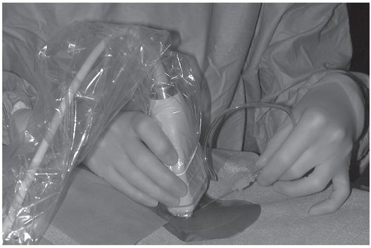
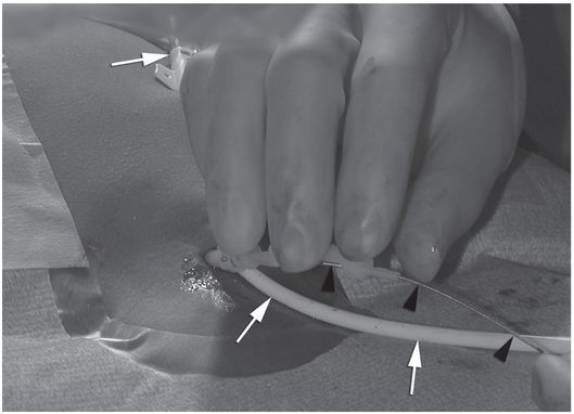
To use US successfully the operator must commit one hand, at least intermittently, to the US transducer (Figure 2.9) or rely upon the assistance of a technologist. Previous US scanning experience is extremely helpful if this approach is selected, and the learning curve may be steep for interventionalists not already well versed in US-guided interventions (Figure 2.10). Ultrasound equipment and associated personnel may place a burden on already crowded interventional suites. Ultimately, once facility is gained by the operator the frequency of success should be high with both methods, and the complication rate associated with both techniques are indistinguishable. Regardless of the guidance technique used for initial access, once the venous system is entered a guide wire is inserted and positioned in the right atrium or IVC and the catheter is inserted under fluoroscopic control.
Ultrasound guidance for venous access. The transducer is placed in a sterile cover containing gel, and sterile gel is applied to the skin. The access needle, target vein, transducer, and US monitor are organized ergonomically in line to reduce operator fatigue. This may require that a second person operate the US keyboard and controls.
In this long axis view, a PICC placed by an IV nursing team at the bedside passes through the brachial nerve (arrowheads) before entering the brachial vein (arrow). When the PICC was removed, the patient’s pain and paresthesia subsided.
If a silastic catheter is chosen, a peel-away sheath is necessary. Although in some cases no tract dilation is necessary, we find that dilating the tract 0.5 to 1.0 French larger than the sheath is helpful and may reduce venospasm. Whether tract dilation is routinely performed, it seems to be extremely important in young infants due to the presence of tough connective tissue about the vein, which catches on the transition zone of the peel-away sheath. This is particularly true when 3 French systems are utilized. Unfortunately, 3 French sheaths have rough transition zones with a rather abrupt change in caliber between the dilator and sheath. In some situations, changing to a longer 3 French dilator (10 cm) in the peel-away sheath helps. If the tip of the peel-away portion becomes deformed it must be replaced or damage to the vein is likely.
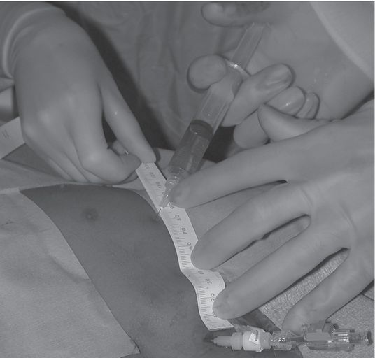
Once the peel-away sheath is in place, location of the catheter tip in the preferred final position must be assured. Of the several techniques available to accomplish this, we prefer a modification of the “bent wire” technique, which we have found reliable, quick, and easy to perform. Additional methods are described in “Technical variations,” below. To determine the length to which the silastic catheter should be trimmed, the guide wire is passed through the peel-away sheath and its tip positioned at the entrance to the right atrium under fluoroscopic guidance. Anatomic landmarks that may be used to approximate the appropriate tip position include a point two vertebral bodies below the carina, the inferior margin of the right mainstem bronchus, or the level of the sixth thoracic vertebra.
A hemostat is clamped to the wire at its exit from the sheath (Figure 2.11a), and the wire is completely withdrawn. The length of the external portion of the sheath is subtracted from the marked length of wire, and the hemostat moved to this shortened length (Figure 2.11b). With the hemostat positioned at the point on the catheter where it will exit the skin, the distal end of the wire now marks the point at which the catheter should be trimmed. Some PICCs have a zone where the catheter has a larger diameter just proximal to its hub. Failure to include this area in the total catheter measurement will leave the catheter too long. The dilator is removed from the peel-away and the PICC, having been cut to the desired length, is inserted.
The tip of the guide wire is positioned under imaging guidance at the desired location (i.e., entrance to the right atrium), and a hemostat is clamped to the wire as it exits the hub.
The guide wire is removed. Once the distance from the hub to the skin entry site has been subtracted, the length of wire remaining is used to mark the point at which the catheter should be cut.
In some instances, the catheter can be successfully positioned by just advancing it through the peel-away sheath into the venous system, allowing venous flow to carry the tip to its desired intra-atrial position. In our practice a 0.018-inch hydrophilic glide wire is inserted into the PICC and together they are advanced into position. This practice is used in most situations since it reduces procedure time and makes catheter positioning easier. Use of a guide wire is generally required for placement of a PICC via the cephalic vein.
When a guide wire is used, an angled glide wire is usually selected since silastic and silicone catheters do not move easily over non-hydrophilic guide wires. A glide wire must be kept wet to function properly, and wiping the wire frequently with a saline-soaked, lint-free pad (e.g., Telfa) kept in hand facilitates its use. On occasion 3 French catheters will not move easily over a moistened hydrophilic guide wire. One must be careful with a wet or lubricated hydrophilic wire since it can easily slip even through a moderately tight grip and the hard won access can be lost in a moment of inattention.
Once the catheter is positioned at the entrance to the right atrium its location is confirmed fluoroscopically by injection of contrast. Any suspicion of malposition or unexpected catheter deviation should be explored with multiplanar imaging. Any catheter tip that impinges on the vessel wall at greater than a 40-degree angle should be repositioned so that it lies as parallel to the long axis of the vessel as possible to avoid perforation. The catheter hub is then secured to the skin (e.g., with a Stat-Lock® or SorbaView® shield) and covered with a sterile, dry, transparent dressing.
When imaging guidance and interventional techniques are used for central venous access, postprocedure radiographs need not be obtained on a routine basis. Occasionally convenience or other circumstances dictates selection of an alternate location for the catheter tip other than the entrance to the right atrium. Regardless, if available a central location is usually preferred. Catheters that end in tributaries of the vena cava have a much higher frequency of complications. Correct position of the tip, as described in “Route of access,” above, is especially important in PICC insertions, as the tip may move up to 3 to 5 cm with changes in arm position and respiration. If the tip is too high in the SVC, it can easily become malpositioned and may require forward flushing or more extensive maneuvers to reposition.
Technical variations
Catheter measurement
Alternatives to the bent guide wire technique include the use of a “single wire” method that allows the operator to leave the initial glide wire in position once access to the right atrium is achieved. This is important when passage from the arm entry site to the right atrium has been difficult due to challenging anatomic factors or venospasm. First, the wire tip is positioned at the projected catheter tip position at the entrance to the right atrium. Subtracting the distance from the back end of the wire (outside of the patient) to the skin entrance site from the total wire length will determine the appropriate length of the PICC to be inserted.
Alternatively, appropriate PICC length can be indirectly measured by anticipating the course of the catheter. The catheter may be placed on top of the child following the course of the wire as monitored by fluoroscopy, from the skin entry site to the desired tip position at the entrance to the right atrium. The PICC is then cut to length and advanced through the peel-away sheath over the glide wire into position. The sheath is peeled open to the skin surface so that the final length of the catheter may be verified before and after the sheath and guide wire are removed.
Postprocedure and follow-up care
At the completion of the procedure catheter course and tip position are documented with fluoroscopy and an image retained.
The catheter is flushed with 1.5 ml of a heparin solution (10 U/ml). The final catheter length and position of the catheter is recorded in the patient’s chart along with any other pertinent details of the procedure (see Table 2.1). Prior to discharge, the patient and family receive thorough education in home care of the catheter and dressing from a member of the interventional staff or vascular access service. When PICCs are placed at the bedside without imaging guidance the catheter tip may not be in a satisfactory position in more than 20% of cases. Therefore all of these patients have a postprocedural chest radiograph to document catheter course and tip position. If the catheter is coiled or is not in the distal SVC or upper right atrium the interventional team repositions the PICC. If the catheter is coiled in the proximal venous system but is long enough it is treated using the flush technique. A 3 ml or 5 ml syringe filled with sterile saline is used to forcefully inject the catheter. In most instances the jet effect at the catheter tip pushes the catheter forward into the appropriate position (Figure 2.12). If the catheter is too short or cannot be flushed into position it is replaced in the IR suite. Parenthetically, we believe that catheter tips positioned in the subclavian vein, brachiocephalic vein, or proximal SVC are of concern, especially those above the SVC. It has been our experience that the short or midline catheters are many times more prone to complication than those placed centrally.
PICC placed by IV team without imaging guidance is coiled in the subclavian vein (arrow).
After forceful saline flush using a 3-ml syringe, the catheter tip (arrowhead) is correctly positioned near the entrance to the right atrium.
PICC removal
At the endpoint of therapy, or when other conditions indicate, someone familiar with the device and the procedure supervises removal of the PICC. A first precaution deserving consideration is that CVCs are easier to remove than to replace. It is sometimes wiser to leave the catheter in place until the endpoint is certain rather than remove it prematurely and subject the patient to a second procedure a short time later.
An uncuffed silicone or polyurethane PICC may simply be pulled out, keeping gentle pressure at the exit site until hemostasis is achieved, then covering the wound with a clean, dry dressing. For every PICC removal, the catheter is inspected for defects, measured, and its length documented and compared with the length recorded at insertion. A significant difference implies fragmentation and possible embolization of the distal fragment. If the PICC is being removed because of suspected catheter infection, the tip is secured under sterile conditions in a suitable container and transported promptly for Gram stain and culture.
A cuffed PICC may sometimes be removed in the same fashion; especially if it is removed before significant tissue in-growth occurs (ten days to two weeks). However, if there is substantial resistance, or if the patient experiences pain during a brief attempt to extract the catheter, this approach may be abandoned in favor of the following.
If extraction of the cuffed PICC is inhibited by tissue in-growth, it may be removed using a minor surgical procedure after the distal tract and exit site have been generously infiltrated with local anesthetic. The external component of the catheter and the area around the exit site are prepared and draped in sterile fashion. Using a narrow hemostat, the exit site is dissected, opening the tract to the cuff. With gentle traction on the catheter, the cuff is brought into view. Using care not to damage the catheter itself, the pseudo-capsule of connective tissue is dissected from the circumference of the catheter just proximal to the cuff with blunt dissection and iris scissors. Once free, the catheter will pull out effortlessly. Vigorous traction on the catheter should be avoided due to risk of catheter fracture and embolization. Once hemostasis is achieved, the exit wound is cleaned, bandaged, and left to heal by secondary intention. A suture is not placed, as the wound is considered “dirty”.
Technical problems and pitfalls
When venospasm occurs it is difficult to resolve, makes successful placement unlikely, adds a considerable amount of time to the case, and usually adds to the cost since other drugs, catheters, and guide wires may be necessary. When venospasm occurs, a variety of approaches may be tried. Unfortunately, no single approach has been especially helpful. In our experience, most venospasm is due to vessel trauma with a guide wire. Therefore, it is best to avoid pushing a wire tip into the wall even if you feel that it is harmless. Also, one should be careful about spinning a directional guide wire as this “helicopter” action may cause minor intimal injury and venospasm. If the cuff is buried too far above the entry point to safely free it in the manner described above, one may perform a cut-down from a point directly superficial to the cuff, taking care not to damage the catheter. The cuff is then freed and the catheter removed as previously described, except that this wound is closed primarily.
When present, there are several options to treat venospasm. Parenthetically, it may be best to find another site for catheter insertion before embarking on this time consuming and potentially costly journey. Reducing the size of the PICC by 1 French may be helpful and is our first choice if luminal patency, albeit diminished, is noted (i.e., if a wire can be passed beyond the region of spasm). Venospasm may be broached from a physiological, mechanical, or pharmacological basis. First, 5 to 30 minutes of patience may be rewarded with relaxation of the spastic region. If a catheter or dilator is already positioned just proximal to the area of venospasm, a brisk infusion of saline may break the episode long enough to allow passage of the catheter. Should spasm persist, various pharmacologic agents have been used with variable success, including nitroglycerine, papaverine, priscoline, calcium channel blockers, or (if the child is under general anesthesia), halothane.
Attempting to pass a silastic catheter through a spastic or narrow region often causes the catheter body to “accordion” distal to the narrow area. A polyurethane catheter may be stiff enough to pass successfully in these situations. While pulling the wire back to a position proximal to the spasm may allow adequate reduction in the catheter circumference to allow it to pass, this maneuver risks losing access entirely and is not usually recommended.
A similar situation may be encountered when attempting to exchange a silicone PICC over a guide wire. If the PICC becomes accordioned even over a glide wire, we have found it very effective to coat the wire, and even the catheter itself, with a biologically inert lubricant, such as sterile mineral oil or silicone spray. The marked reduction in friction that results is often sufficient to allow passage of the catheter beyond the narrow region.
Complications
Infection, thrombophlebitis, tip occlusion, catheter damage and mechanical malfunction, dislodgment and malposition are the most common complications associated with PICC lines. In general, complications associated with PICC lines and other central venous access devices are similar in nature, differing primarily in frequency. Phlebitis and catheter dysfunction are discussed below. A more complete discussion of catheter-related infections, malposition, tip occlusion, thrombosis, mechanical malfunction, and intravascular foreign body management is provided under “Complications” in the section on “Central venous catheter (CVC) insertion.”
Catheter-related thrombophlebitis
Although there have been reports of thrombosis in as many as 23 to 38% of PICC lines, more recently the prevalence of PICC-related thrombosis in children when placed by an experienced interventional radiology team is less than 1%. The incidence of thrombosis was related to the site of access, with the highest incidence in the cephalic vein (57%), followed by the basilic (14%), and the brachial (10%). There is a substantial prevalence of phlebitis (defined as erythema, swelling, pain, or palpable cord overlying the catheter course) associated with PICC insertions. Since this is often a self-limited process, it is important to differentiate phlebitis from catheter-related infection, to prevent unnecessary catheter removal. When phlebitis is suspected, treatment with a warm compress and a tincture of time is often sufficient to resolve symptoms within 24 hours. If necessary, treatment with a non-steroidal anti-inflammatory drug (e.g., intravenous Torudol®) is helpful and may be diagnostic of non-infectious inflammation. Heparin solutions (either 1 U heparin/ml infusion given continuously, or 100 U/ml of intermittent flush each six to eight hours in locked catheters) significantly decreases the risk of phlebitis in peripheral angiocatheters. To our knowledge no prospective trial has proven similar effect in PICC lines. However, this seems a reasonable intervention in situations where phlebitis is suspected, or an increased risk of phlebitis can be anticipated (e.g., difficult insertion, venospasm at insertion, small difference between vessel and catheter diameter).
There has been increased interest in recent years in “midline” or non-central placement of peripherally inserted catheters, especially as a method to salvage difficult PICC insertions complicated by venospasm, venous tortuosity, venous valves, or other factors. It is clear, however, that non-central location of the PICC tip significantly increases the risk of phlebitis, occlusion, leakage, and other complications. In fact, we recommend that if a catheter tip is noted to be outside the ideal “landing zone,” that is, between the inferior margin of the right mainstem bronchus and a point two vertebral bodies below the carina, that the tip should be repositioned or the catheter replaced, especially in patients at high risk of catheter-related complications or those with a chronic diagnosis likely to require central access into the foreseeable future.
Catheter dysfunction
Catheter dysfunction usually presents as loss of ability to obtain blood return, total occlusion (catheter does not flush or draw), or pain during flushes or drug administration. These problems can be managed according to a logical protocol that emphasizes a definitive diagnosis and management plan, preserves access safely when possible, and conserves cost.
When pain or edema accompanies infusion, this problem should be evaluated promptly with contrast-enhanced dynamic fluoroscopy. Other studies either delay a definitive diagnosis or increase risk of injury. Pain during injection is usually caused by extravasation of fluid causing increased interstitial pressure in the subcutaneous or perivascular tissues. The principal purpose of the examination is to identify the location and etiology of the extravasation. At times, fluid extravasates through a very subtle pinhole defect in the catheter, often related to rough handling of the catheter during insertion. It is imperative to image the entire course of the catheter prior to contrast injection, and to compare this with the course and position of the catheter at the time of initial insertion. If the position has changed, the tip may no longer be intravascular. One must then carefully observe as the contrast first flows through the catheter.
Extension of a fibrin sheath from the tip to the venous entry site may allow reflux along the distal length of the catheter and into the perivascular tissues. Attempts to resolve a fibrin sheath with instillation of a fibrinolytic agent are occasionally effective, but this is often simply a temporizing intervention. Stripping the catheter with a transfemoral snare is usually successful, but should be reserved for those cases where access is lifesaving or difficult to achieve. The simplest and most definitive therapy is to change the catheter over a wire.
Catheter fractures and tears are among the most common PICC-related complications, occurring in up to one in ten patients. Most of these may be attributed to tearing of the catheter during insertion, overpressuring during injection (e.g., injecting forcefully through a small-caliber syringe), or traction on the catheter hub junction. Such damage to the catheter may range from a pinhole to outright disruption, and may appear on imaging as a subtle line of contrast along the outer wall of the catheter to frank extravasation to an apparent discontinuity in the catheter itself. This common problem has received little attention in most reviews of CVCs and PICCs, especially how to repair leaks and tears in silastic catheters. Although it is technically easy, physicians seldom perform the procedure and it is therefore not widely known (Appendix 2.B). When there is any evidence of damage to the catheter, strict caution should be employed during its removal to avoid catheter fragmentation and embolization of the distal fragment. At least, the catheter should be removed under fluoroscopic control. If embolization appears imminent, the distal component may be guided gently during removal with a transfemoral snare.
Complete occlusion of a CVC (inability to flush or draw) may be due to tip thrombus or fibrin sheath formation, catheter kinking, malposition, or a variety of factors discussed elsewhere in this section. Again, simple causes of dysfunction should be explored before more costly or invasive studies are pursued. For example, it is surprising how often disengaging the clamp, unkinking the external portion of the catheter or unclogging the hub is all that is necessary to restore function. Since it is difficult to perform a contrast study through a catheter that will not flush, it may be worthwhile attempting a forceful injection of contrast or saline prior to removing the catheter. Serial attempts may be made with successively smaller syringes (from 5 ml to 1 ml), remembering that smaller syringes generate greater pressure. Only experienced personnel should use syringes smaller than 10 ml, to avoid damaging the catheter and causing tissue injury.
Inability to obtain blood return when the catheter still flushes often relates to a ball-valve mechanism operating at the catheter tip, due to one of several factors: wedging of the catheter tip against the vessel wall (malposition or fibrinous adherence to the wall), tip thrombus, or fibrin sheath. A contrast-enhanced fluoroscopic study may be required to differentiate these causes in order to direct specific treatment. However, simpler causes may be ruled out first. For example, a change in patient position (elevation of the ipsi- or contralateral arm, rolling from supine to prone, deep inspiration or expiration, etc.) may be enough to free the catheter tip and achieve adequate blood return.
A high calcium phosphate product in the infused solution, or certain acidic or basic drugs may cause precipitation along the catheter anywhere from the hub to the tip. Similarly, a nutrient admixture or piggybacked lipid solution may cause a slow build up of lipid thrombus at the tip. A review of the patient’s medical course may reveal such a common cause of occlusion. Treatment depends on the precipitating factor (Appendix 2.C).
If the medication history is unproductive, and tip thrombus is suspected, a trial of thrombolytic therapy is warranted (Appendix 2.C). However, prior to administration of tissue plasminogen activator (tPA) a chest radiograph is obtained to confirm the intravascular course of the catheter in order to avoid tissue injury or bleeding complications. Irregularity of tip position, catheter conformation, or catheter motion may prompt further investigation with contrast-enhanced fluoroscopy. Angulation of the fluoroscope may help resolve real kinks or conformational abnormalities from apparent kinking caused by tortuosity of the catheter course through the imaging plane.
In addition to watching for extravasation and abnormalities of catheter position, the catheter length and motion of the tip is carefully observed. If the catheter is shortened compared to prior studies, this may indicate fragmentation, and the distal (embolized) fragment must be located and, if possible, recovered (Figure 2.13). If the tip moves freely, but the contrast jet streaming from the tip “sprays” diffusely or appears to be deflected (Figure 2.14), this indicates likely tip thrombus or fibrin sheath, as discussed elsewhere. Abnormal tip motion or lack of tip mobility may signify adherence of the tip to the vessel wall, or entrapment of the tip within a deep venous thrombus (Figure 2.15). This finding cannot be adequately evaluated with contrast through the catheter alone, and a focused venogram or US scan may be indicated. If venography is used, it is performed with simultaneous bilateral contrast injection if possible, with gentle compression of the jugular vein, to reduce inflow artifact. For this reason, we routinely request that patients referred for venographic catheter studies are provided with peripheral angiocatheters bilaterally prior to transport to interventional radiology.
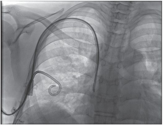
A one-year-old girl with trisomy-21, atrioventricular canal repair, and intestinal failure had a left IJ tunneled central venous catheter inserted by the surgical service for nutrition.
The catheter tip (arrowhead) is positioned within the persistent left SVC.
Four months later, the catheter fractured (arrow) during attempted removal.
A 15-mm snare is deployed through a transjugular sheath passed into the left SVC.
The loop snare was closed over the tip of the catheter, and the fragment was recovered through the sheath without further complication.
PICC inserted with tip (arrow) in mid-subclavian vein. Contrast injection demonstrates occlusive thrombus.
Central venous catheter (CVC) insertion
Introduction
Compared to PICC insertion, placement of CVCs is usually technically easier, faster, and more often successful, particularly in small children. The internal jugular vein (IJV) is the preferred venous entry site. If the IJV is not available, a PICC, femoral CVC, or subclavian vein (SCV) can be used. In the past, the use of the femoral vein for CVC insertion has generally been discouraged due to restriction of patient movement and higher likelihood of infection especially in younger children who wear diapers. However, the use of a tunneled, cuffed CVC has made this route useful especially in young children, children with occluded IJVs, those with complex congenital heart disease, and for emergent indications or temporary access (e.g., CVC, apheresis, hemodialysis). Additional considerations regarding femoral location and device selection in older patients may include cosmetic appearance as well as interference with clothing, sport, sexual relations, and seatbelt use, for example. It is generally accepted that subcutaneous tunneling of long-term CVCs significantly reduces the risk of complications, especially catheter-related infection. There is some evidence that tunneling may also reduce the risk of infection in short-term CVCs, especially transjugular CVCs, although prospective evidence in children is not yet available.
In our opinion, use of the subclavian vein as a primary choice for venous access should be discouraged. If the subclavian vein is used it should be only after all other options have been considered. There are several reasons why the subclavian vein should not be considered as a primary choice for venous access including its strategic position as the inflow vessel from the ipsilateral extremity and the neck, and its higher rate of complications when compared to the IJV.
Indications
Central venous catheters are indicated for treatment of both emergent and chronic conditions. Emergent access for volume replacement, blood sampling, or administration of life-saving medications is probably best achieved by the most expedient method available. Usually, this means “blind” percutaneous insertion using anatomic landmarks, or even intraosseous access, by emergency department, intensive care, or surgical personnel. Image-guided placement is normally best reserved for less urgent indications. In the future there will likely be more US-guided bedside insertion of CVCs by interventionalists and other physician and nurse groups (Table 2.2).
Some of the more common indications for CVC placement in the pediatric population are for chemotherapy in oncology patients; for parenteral nutrition; and for dialysis in nephrology patients. Central catheters are also helpful for blood product replacement in hematology patients; prolonged antibiotic therapy (e.g., in cystic fibrosis and osteomyelitis patients); fluids, electrolytes, and medications in intensive care patients and children with metabolic diseases; and a variety of similar applications.
Few contraindications to placement of CVCs exist. An uncorrectable coagulopathy has traditionally been a contraindication for invasive procedures. However, it is precisely these seriously ill children who require central venous access for therapy. Thus, it has been our practice to take all appropriate measures to correct abnormal laboratory data. In cases where correction of low platelets or prolonged PTT has been attempted without success, we perform the procedure with platelets or fresh frozen plasma infusing to maximize safety. Hemophiliac patients with high titers of inhibitors who require central access for factor and blood product replacement are particularly challenging. Although these patients may benefit from immune tolerance treatment and recombinant factor replacement they are usually best approached in close consultation with a pediatric hematologist. Frankly, if uncontrollable bleeding is observed after US-guided access to a neck vessel, one ought first look for mechanical disruption of the catheter (e.g., perforation by a retention suture) before attributing the bleeding to a coagulopathy.
In these situations, an easily accessible peripheral site for PICC or a large central vein well visualized by US is selected. In the latter case the right internal jugular vein (RIJV) is strongly preferred. The RIJV has the advantage of being the largest and easiest central vein to cannulate with the most direct course to the right atrium. It also facilitates accurate measurement of catheter length, and allows for the shortest procedure time.
In addition, in these instances a temporary CVC (tapered polyurethane CVC) may be inserted (Figure 2.16). Since neither tract dilation nor a peel-away sheath is required procedure time is minimized. Additionally, because the catheter completely fills the tract and venous puncture site, the risk of bleeding is decreased. In both theory and practice cannulation of an IJV has the lowest risk of complications since hemothorax and pneumothorax are less likely to occur. Another significant advantage of the RIJV approach is the ease of achieving postoperative hemostasis and monitoring for delayed bleeding. Placing the patient in a reverse Trendelenburg or semi-upright (sitting) position to lower venous pressure will facilitate hemostasis when the IJV is used.
3-French tapered non-cuffed polyurethane temporary central venous catheter with access needle, guide wire, and dilator.
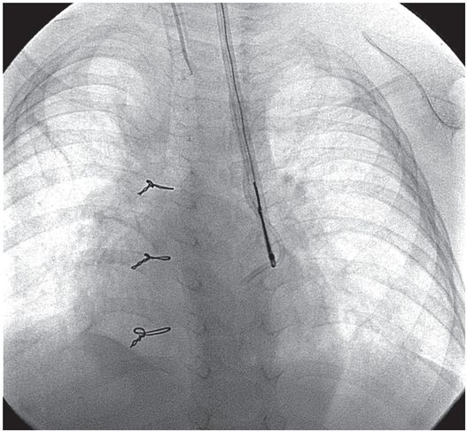
A word of caution when inserting temporary CVCs! These catheters are stiffer than silastic or silicone CVCs and have a tapered tip (Figure 2.17). Thus, it is important to avoid contact with the cardiac wall, floor, or ceiling. If forward pressure is placed on the cardiac wall perforation and tamponade may occur. The IR or diagnostic radiologist should be mindful of the catheter position and the conformation of its path and tip location. If the tapered catheter abuts the wall and is bowed one should be concerned about the potential for injury and have the catheter repositioned as soon as possible.
Ten-year-old boy with thrombotic thrombocytopenic purpura requiring plasmapheresis was unable to receive therapy due to catheter malfunction. The temporary pheresis catheter is kinked at the venotomy site, a complication similar to catheter “pinch off” previously described. Note the tapered tip (arrowhead) of this stiff catheter projecting toward the lateral wall of the SVC. This patient is at increased risk of vessel perforation.
Technique: internal jugular CVC insertion
Equipment
The selection of needles, catheters, guide wires, and other equipment varies considerably depending on the experience and preference of the interventionalist and the size, age, and condition of the patient (Table 2.3). In the pediatric age group a range of access needle sizes, catheter diameters, and lengths should be available to the interventionalist. The needle size selected depends on the child’s weight and size.
When a CVC is inserted, a single wall needle is preferred since it is more echogenic than an angiocatheter. For very small infants it is occasionally necessary to begin with a smaller needle and wire, such as a micropuncture kit (Figure 2.18), exchanging for a larger dilator or peel-away sheath once access is achieved. Children weighing 10 to 20 kg are usually accessed with 20- or 22-gauge needles. Occasionally, in larger children, 19- or 18-gauge needles are used. Again, the needle selected is often based on operator preference since all types work well.
Micropuncture introducer sets, such as the one pictured here (Cook, Bloomington, IL) are usually introduced over a 0.018-inch platinum tipped (nitinol) or stainless steel wire, placed through a 21-gauge access needle. Once the coaxial introducer is in position, the inner core is removed, leaving a 4 or 5 French outer catheter in place, which will accept a 0.035- or 0.038-inch guide wire.
Regardless of the needle selected, we prefer to place a connecting tube between the needle and the syringe so that gentle suction can be applied. Once “free” blood flows into the tube one can be confident that the needle tip is intraluminal. Also, use of a connecting tube protects against significant movement or accidental dislodgment of the needle tip with unexpected patient or operator motion.
Central venous catheters are available in a wide range of sizes and configurations. In most instances the choice of access device in a given case is made giving consideration to a combination of factors such as the referring physician’s preference, the child’s illness, and anticipated length of treatment. Our recommendations are included under “Route of access,” above. Catheters from 3 French to 9 French are available for use in the pediatric population. Five and 7 French single lumen catheters are the catheters most commonly used. Dialysis or apheresis catheters are generally 7 to 14 French in size. One may choose from a variety of catheter types including PICCs, non-tunneled (temporary) catheters, tunneled catheters, dialysis catheters, and indwelling ports. The final choice depends on the expected catheter use and the dwell time. In addition, one may choose catheters with single, double, or triple lumens. It is important to recognize that for the same outer diameter increasing lumen number decreases cross-sectional area (and therefore, flow) by at least 16 times. Also, blood return is substantially more difficult to obtain in 3 French and smaller catheters making them undesirable for some uses. In general, the catheter with the fewest number of lumens and smallest internal diameter that will satisfy the clinical need is selected. This will maximize the diameter of the lumen and flow through it, while minimizing the potential for catheter dysfunction especially in the small French sizes.
Patient preparation
As is the case for all major interventional procedures, informed consent is obtained from the patient when age permits, or from the parent or legal guardian. When appropriate, assent is obtained from the minor patient. For CVC insertion the technical aspects of the procedure and its risks are reviewed with the consenting adult, usually in the presence of the child. The technical factors, most common risks, benefits, and alternatives are carefully explained, including sedation problems, bleeding that could require transfusion or operative intervention, pneumothorax, hemopneumothorax, and infection. Uncommon problems such as catheter fragmentation and distal embolization are rarely discussed in detail.
The evaluation of the individual prior to placement of a CVC varies with the indication and the status of the child. In general, a coagulation profile is obtained for documentation of the PT, PTT, CBC, and platelet count. In rare instances the bleeding time is measured.
For CVC insertion the IJV vein is the preferred entry site, especially when there is an increased risk of bleeding or if the child is severely ill. A decision to tunnel the catheter is made on a case-by-case basis. A tunneled catheter is placed in children who are expected to go home with the central line in place, require access for at least two weeks, or those who will need frequent access. In high-risk situations, especially in children with an uncorrected coagulopathy, tunneling is avoided because of the potential for bleeding and subsequent infection. If necessary, tunneling can be performed at a later date when the risk level is appropriate. In a high-risk population, a temporary line may be preferred over a silastic catheter for ease of insertion, shorter procedure time, and avoidance of tract dilation and need for a peel-away sheath. There appears to be a lower incidence of postprocedural bleeding with this approach because of the avoidance of tract dilation and the precise fit of the polyurethane catheter into the vein promotes hemostasis.
Prior to CVC insertion, all children are kept NPO for at least six hours so that they can be safely sedated. The child requiring general anesthesia is prepared according to the anesthesiology department protocol as if the child were to go to the operating room. Standard laboratory tests include a CBC, platelet count, PT, PTT, and (rarely) a bleeding time. Prophylactic antibiotics are not routinely given.
Once in the room, the child is placed on the angiography table and secured with Velcro straps to avoid falling. If the procedure is performed on a tilting angiography table, placing the patient in approximately 10- to 15-degree Trendelenburg fills the jugular vein more prominently, allowing the vein to be punctured with less risk to surrounding structures, and decreasing the risk of air embolism. All children are monitored with pulse oximetry and an automated blood pressure device. A sensor for pulse oximetry is secured to a finger, toe, foot, or rarely an earlobe. Leads are placed for cardiovascular monitoring. Reusable sensors are available for small babies.
Children presenting for primary CVC insertion have a peripheral IV placed if one is not already present. Preprocedural US is performed and the prospective entry site is marked on the skin with an ink marker.
Standard technique
In most instances the IJV, usually the right, is the largest and easiest central vein to puncture (Table 2.5). This is particularly important in small infants in whom access of the subclavian vein may be challenging and carries a higher risk of malposition, pneumothorax, and other complications.
Obtain preprocedural laboratory studies.
Select entry site with US.
Prepare and drape skin.
Locally anesthetize entry site.
Small skin incision at entry site.
Puncture internal jugular vein using real-time US guidance.
Aspirate until free blood return. Confirm position with venography if necessary.
Insert guide wire into right atrium, IVC, or hepatic vein.
Dilate tract (if silastic catheter used).
Exchange dilator for peel-away sheath.
Measure distance from entry site to upper right atrium.
Insert CVC.
Inject contrast to confirm satisfactory position.
Suture incision closed.
Cover entry site with a 2 × 2 gauze and occlusive dressing.
Heparinize CVC.
Document procedure in medical record.
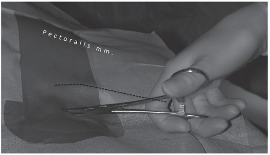
Caution should be exercised when selecting the site of entry into the internal jugular system. The distance from the jugular bifurcation to its junction with the subclavian vein is short in small infants and children with short necks. Therefore, it is important to choose an entry site at least 2 to 3 cm superior to the clavicle (Figure 2.19) to minimize the risk of penetrating the posterior wall of the distal jugular or subclavian vein and entering the apical pleural space, or injuring the subclavian artery. If these complications occur, a life-threatening hemothorax may occur. To avoid this problem it is our practice to select an entry site two fingerbreadths superior to the clavicle and to puncture the vessel with the needle at about a 6-degree inclination.
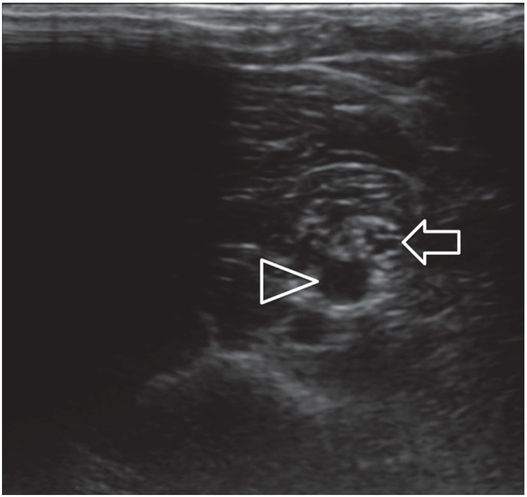
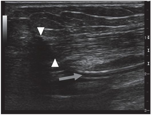
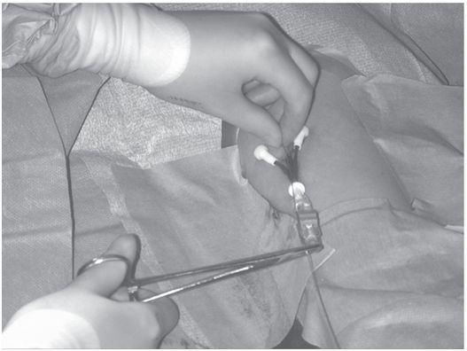
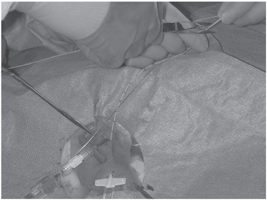
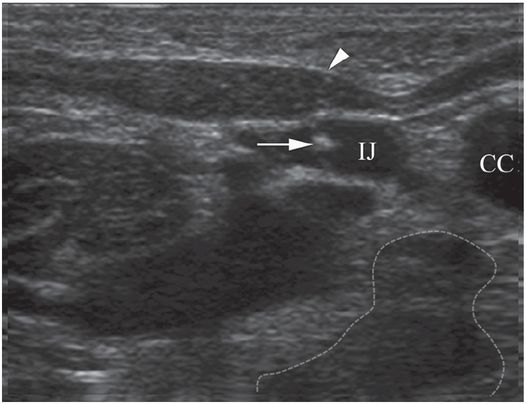
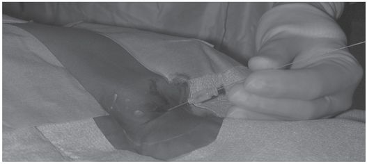
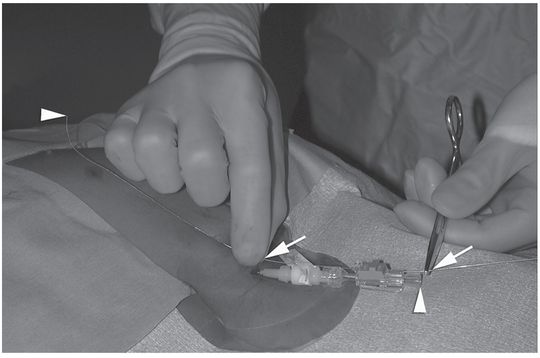
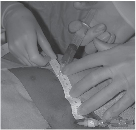
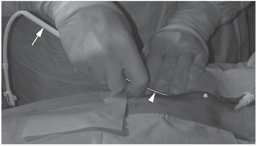
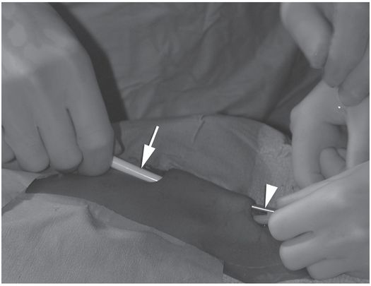
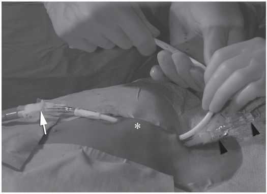
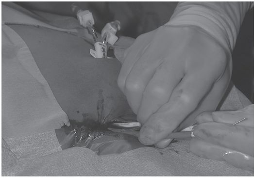
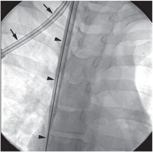
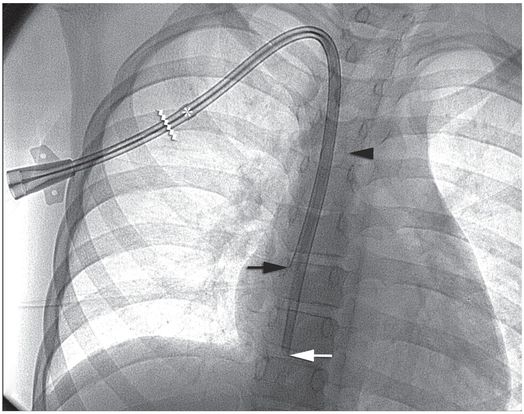
Ten-year-old girl with nephrotic syndrome for IJV dialysis catheter insertion. (a) A short skin incision is made at least 2 to 3 cm from the clavicle (dotted line), up to halfway between the clavicle and the angle of the jaw. The tract is dilated by blunt dissection with a curved Kelly forceps. (b) Under US guidance the IJV is punctured with an access needle (c) as shown in this linear US image, passing through the sternal head of the sternocleidomastoid muscle (arrowhead). The needle tip (arrow) is seen within the lumen of the internal jugular (IJ). Care must be used to distinguish the vein from the common carotid artery (CC), by compression and Doppler flow, and to guard against inadvertent puncture of other vessels, nerves, or the cupola of the lung (dotted line). (d) A 0.018-inch mandril guide wire is advanced through the micropuncture needle, and the needle is exchanged for an introducer sheath. (e) After verifying the position of the guide wire tip at the entrance to the right atrium under fluoroscopy, the wire is clamped at the hub and withdrawn. The difference between the clamp and the skin entry site (arrows) is subtracted from the initial measurement (arrowheads) to determine the length of the catheter from the venotomy site to the proximal lumen tip. (f) This is shown on the catheter as the distance between the white arrow and arrowhead. The remaining distance (arrowhead to black arrow) is measured. (g) This becomes the distance from the venotomy site to the skin entry site. The skin entry site and the subcutaneous tract are generously infiltrated with local anesthetic. (h–i) The tunneling device (arrowhead) is attached to the catheter (arrow) and the subcutaneous tract is formed, keeping the tip of the tunneler (asterisk) in the subcutaneous layer but superficial to the clavicle. (j) The catheter is pulled through the tract, until the cuff (asterisk) is several centimeters beyond the skin entry site. Both the check-flow valve on the introducer (arrowheads) and the clamps on the catheter (arrow) should be closed to prevent air embolus. (k) With the catheter (arrows) through the subcutaneous tunnel, the mandril wire and inner core of the introducer are removed and a 0.038-inch guide wire is inserted, as deep as the IVC if possible. (l) The tract is prepared with serial dilators up to the diameter of the peel-away sheath. (m) Dilations and sheath insertion are performed under fluoroscopic control, maintaining the dilators (arrowheads) parallel to the mediastinum and plenty of wire beyond the tip to prevent inadvertent injury to the heart or great veins. (n) Split dialysis catheters are designed for the proximal tip (black arrow) to be positioned at the entrance to the right atrium, in this case approximately two vertebral bodies below the carina (arrowhead), with the distal tip (white arrow) in the atrium itself, to maximize flow and minimize recirculation. Note that the cuff (asterisk) is well beyond the skin entry site (wavy line) to assure in-growth and long-term stability.
Although venous access may be achieved by non-guided puncture using anatomic landmarks, real-time image guidance to assist venous entry is safer and more efficient in most cases. In our laboratory US is used preferentially. We have found that imaging the vessel in the short axis is best since it nicely demonstrates the relationship of the needle to the middle of the vessel. The long axis can also be successfully used for guidance and some operators prefer this approach. Ultrasound may also identify anatomic reasons for difficult access in some cases. Conversely, use of US without adequate training and experience and without knowledge of the patient’s venous history can lead to severe complications (Figure 2.20), including venous or arterial injury, pneumo- or hemothorax, pulmonary hemorrhage, hypovolemic shock, and death.
Urgent access of the right internal jugular vein was attempted with US guidance by ICU personnel in this one-year-old female in renal failure who had had the right jugular vein ligated with extracorporeal membrane oxygenation (ECMO) as a newborn.
Diagnostic angiography after puncture of a vascular mass the following morning demonstrates a pseudoaneurysm (asterisk) of the right vertebral artery (arrow).
A 9.5 Fr double lumen catheter was successfully placed via the left internal jugular vein that provided satisfactory hemodialysis for three months until the patient’s death from unrelated sepsis.
Selecting the correct catheter length can be challenging, more so when entering from the left IJV. With a longer length of catheter and tunnel for the CVC to recoil into, the degree of shortening tends to be greater. Especially with tunneled catheters, it is easier to pull the catheter back a short distance to achieve appropriate position than to advance it forward the same distance. Therefore, if in doubt it is helpful to measure the catheter a few millimeters longer than otherwise anticipated. When a tunneled catheter or port is placed in an obese or large-breasted patient, care must be taken to account for differences in location of soft tissues between the recumbent and upright positions. The degree of catheter migration may be unexpected and may result in several centimeters of upward movement in the catheter tip (Figure 2.21).
Sixteen-year-old girl with acute lymphoblastic leukemia (ALL) and an indwelling port insertion for chemotherapy.
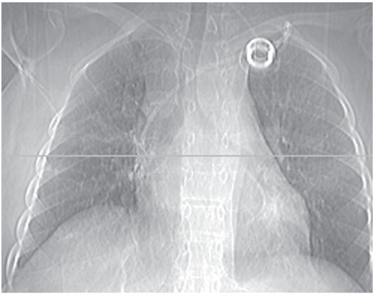
With the patient recumbent, the port catheter tip appears to be in a satisfactory position. The horizontal line on this CT topogram indicates the level of the most inferior axial image on which the tip was still visible.
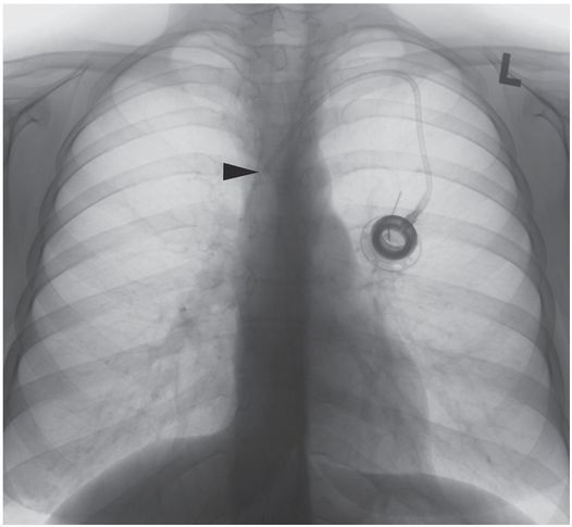
In an upright position, movement of breast tissue results in superior migration of the port catheter tip, approximately 1¾ vertebral levels, with the tip (arrowhead) now abutting the lateral wall of the SVC. Taping down the breast tissue before catheter insertion may help achieve a more reliable final position.
While somewhat complex non-radiographic methods have been described for positioning the catheter tip (such as intra-atrial electrocardiography and transesophageal echocardiography), radiological control is definitive and non-invasive, and obviates postprocedure radiographic confirmation in most cases. The inferior margin of the right mainstem bronchus, the right tracheobronchial angle, the carina, the level of the sixth thoracic vertebra, the level of the third anterior intercostal space, and the lateral deflection of the radiographic “right heart border” have all been suggested as anatomic landmarks that may be used to determine the appropriate catheter length. None of these recommendations arise from prospective study of the relationship between an unequivocal catheter position and the associated rate of mechanical or other complications. Many who respond to rare events such as cardiac perforation and lethal tamponade caution against positioning the catheter tip closer to the atrium than the pericardial reflection. In a particularly erudite editorial, Fletcher and Bodenham note that this latter recommendation is likely to lead to equally serious if less dramatic complications. We agree with their conclusion that “the catheter tip should be placed in as large a vein as possible, ideally (for non-dialysis catheters) outside the heart and parallel with the long axis of the vein such that the tip does not abut the vein or heart wall end-on.” Until an appropriate study is completed in children, we recommend that (1) the position of each catheter tip be recorded unequivocally, as the number of vertebral bodies (whole and fractional) the tip is located below the carina on a fluoroscopic image or plain chest radiograph, and (2) a position from the intersection of the catheter with the inferior margin of the right mainstem bronchus to a point two vertebral bodies below the carina is the safest “landing zone” overall in our experience.
Once the prospective entry site has been sonographically evaluated and marked, the sterile equipment is uncovered and the entry site (including the chest wall if a tunneled line or port is planned) is prepared and draped in sterile fashion. The skin (and tunnel tract if necessary) is then generously anesthetized using a 30-gauge needle with buffered lidocaine. A small skin incision is made (just large enough to accommodate the diameter of the catheter or cuff to be inserted, Figure 2.19a) and a single wall or sheathed needle, is used to access the vein, according to the operator’s preference. If it is consistently difficult to achieve a clean single wall puncture without undue compression of the vein, it may be helpful to use an access needle with a more acutely angled bevel.
In young children the puncture needle is maintained somewhat upright at approximately a 60-degree angle to the skin. The US transducer is kept perpendicular to the skin surface with some cranial angulation (Figure 2.19b) to improve conspicuity of the bevel. The jugular vein must be differentiated from the carotid artery (Figure 2.19c). In general, the jugular vein is larger, non-pulsatile, and enlarges with Valsalva maneuver or a Trendelenburg position. Compression and color Doppler imaging are helpful in verifying the appropriate vessel. If the jugular vein is superficial to the artery, lateral angulation of the US may separate the two vessels and allow a safe window for access.
The puncture needle is directed toward the center of the transducer to its anticipated focal point. An 8 MHz curvilinear to 18 MHz linear transducer, covered with a sterile plastic sleeve, is most commonly used for imaging. The vessel is imaged in the transverse plane so that the relationship of the needle tip to the center of the vessel can be appreciated. Because the jugular vein is highly compliant, care must be taken to achieve a clean puncture of the anterior wall without perforating structures posterior to the vessel lumen. The needle is attached to a connecting tube and 10 ml syringe containing normal saline and suction is applied as the needle is withdrawn. In neonates, the IJV is extremely collapsible. As a result, it is sometimes useful to substitute a smaller syringe in order to avoid collapsing the vessel and interrupting free blood return. When blood return freely flows the tube is disconnected. A guide wire is then inserted and directed into the right atrium or IVC under fluoroscopic control (Figure 2.19d).
If a polyurethane catheter (e.g., temporary central lines) is selected the catheter may be inserted directly without tract dilation or placement of a peel-away sheath. Because they cannot be cut to length, the correct length of temporary, apheresis, and dialysis catheters needs to be selected (Figure 2.19d–f). If a non-tunneled or tunneled silastic or silicone catheter is chosen (see “Creation of a subcutaneous tunnel,” below), a peel-away sheath must be inserted before the catheter can be introduced. The tract is dilated to the diameter of the peel-away sheath prior to its introduction. For small diameter catheters, this is performed as a single dilation. For large bore catheters, this may require two or three intermediate dilations. For example, in anticipation of a 14 French dialysis catheter (which requires a 17 French peel-away sheath), the tract may be serially dilated with 10, 12, and 16 French dilators (Figure 2.19l). Each dilation is monitored fluoroscopically, taking care to maintain proper alignment with the vessel, and to maintain an adequate length of guide wire beyond the tip of the dilator, to prevent vascular or atrial injury (Figure 2.19m).
Three points may be considered with regard to the peel-away sheath. First, to avoid accidental dislodgment or malposition, it is important that the tip of the outer sheath be positioned deeply enough in the vena cava that secure access will be maintained when the inner dilator is removed. Second, to avoid vascular or atrial perforation the peel-away sheath is best advanced over a guide wire under fluoroscopic control and should not be seated deeply within the right atrium. Third, to assure that the catheter may be introduced easily without undue blood loss, at least 2 to 3 cm of the outer sheath are left outside the skin at the venous entry site.
The wire and dilator are carefully removed, and the sheath is clamped at the skin before the dilator is completely withdrawn (the wire must be pulled back within the tip of the dilator so it is not clamped in the sheath!). This allows unhurried introduction of the first 2 to 3 cm of the catheter tip with very little risk of air embolus or substantial blood loss, as described below. The sheath is unclamped and the rest of the catheter is advanced. The tip position is verified with fluoroscopy before the peel-away sheath is removed.
Regardless what catheter type is used, the CVC length is determined using the bent guide wire technique (Figure 2.19e–g) also described under “Peripherally inserted central catheter (PICC) insertion,” above (Figure 2.11). At the completion of the procedure contrast is injected to document catheter position and evaluate for potential adverse events. After contrast injection the CVC is flushed with saline and the line is heparinized. The catheter is then sutured in position and covered with a clear plastic, sterile, occlusive dressing (e.g., Opsite® or Tegaderm®).
Creation of a subcutaneous tunnel
In patients needing medium- to long-term venous access (weeks to months) a tunneled line is indicated (Table 2.6). A subcutaneous tunnel is created after initial venous access has been secured. In appropriate situations (e.g., patients on certain bone marrow transplant protocols) a preexisting indwelling port may be safely exchanged for a tunneled CVC, either using the existing tract or preferably developing a new subcutaneous tunnel.
| Select exit site for the tunnel. |
| Prepare and drape sterile field. |
| Apply generous local anesthetic to tract. |
| Make small incision for catheter exit. |
| Insert tunneler and create a tract. |
| Pull a suture through the tract. |
| Tie the suture to the tip of the CVC and pull through tract until cuff is positioned within distal 1/2 to 1/3 of tract. |
| Insert CVC into upper right atrium via peel-away sheath. |
| Remove peel-away sheath. |
| Inject contrast to confirm satisfactory catheter position. |
| Close incisions. |
| Cover with 2 × 2 gauze and occlusive dressing. |
| Heparinize catheter. |
Once guide wire access to the vessel is secured, the prospective course of the tunnel should be carefully planned. One must avoid sharp turns or angulation that might result in catheter kinking. This is especially important for insertion sites higher in the neck, where the risk of catheter kinking is increased.
The preferred sites for catheter exit are over the lateral chest wall (superolateral to the nipple is preferred) or superomedial to the nipple. It is important not to injure the breast bud, which could result in abnormal breast development. Once the path of the tunnel and the exit site are chosen, the tract is anesthetized (Figure 2.19g) using a long thin-gauge needle (e.g., 22-gauge Chiba). An incision just large enough to receive the tunneling device and retention cuff is made.
A variety of instruments may be used for tunneling including a hemostat or curved Kelly for short tunnels, or one of many rigid or malleable tunnelers for longer tracts. We prefer to use a malleable uterine sound (Figure 2.22), which has a hole in its tip through which a long suture can be tied. The device is inserted in either end of the potential tract and advanced through the subcutaneous tissue until it exits through the other end (Figure 2.19h–j).
A uterine sound or similar blunt-ended malleable device is used to create a subcutaneous tunnel for central venous line insertion.
Occasionally, especially when inserting lines into the IJV there is too much angulation in the course of the tract at the level of the clavicle for the rigid tunneler to safely and easily get to the entry site. Thus, a third incision at the level of the clavicle may be required to create an “interrupted” tunnel. The best location for this incision is at the point of maximal angulation. The tunneler can be brought out at this point and reinserted making it easier to complete the tunnel. In this situation it is important to be sure that the new tract starts deeply enough so that the catheter does not come through the skin.
The silastic central line is attached to the tunneler and pulled through the tract making sure that the retention cuff is positioned within the distal half to third of the tunnel. Having measured the length of the catheter from the venous entry point in the neck to the entrance of the right atrium using the bent guide wire technique, the catheter is trimmed to the correct length. If a Groshong type catheter is used, the measuring steps can be omitted since it can be trimmed from its proximal end once the tip is properly positioned.
The catheter is then inserted through the peel-away sheath and its final position confirmed. To accomplish this, a hemostat is positioned transversely across the outer sheath near its entry point at the skin. The inner dilator is slowly removed from the peel-away sheath, clamping the outer sheath closed with the hemostat prior to removing the last couple centimeters of the dilator. In this manner, the first few centimeters of the catheter may be introduced to the level of the clamp without concern for blood loss or air embolus.
With the distal catheter and proximal sheath held firmly, the clamp is carefully removed and the circumference of the sheath restored to allow the catheter to be advanced without difficulty. This step is most easily accomplished with the help of an assistant. Especially with narrow diameter catheters (e.g., 3 or 4 French), there may be resistance to initial passage of the catheter through the sheath. If so, a non-toothed pick-up may be used to assist the catheter’s advancement, taking small bites in close proximity to the end of the sheath. Care must be exercised to avoid abrading or perforating the catheter wall during this manipulation.
As the final centimeters of the catheter are inserted, the sheath may be peeled back (not advanced) to the level of the skin, and the position of the catheter tip is evaluated prior to complete removal of the sheath. With the tip in a satisfactory position, the sheath is peeled back and removed, taking care not to withdraw or dislodge the catheter during this step. The last bit of catheter is advanced into the neck incision and the skin is closed, usually with a single 4–0 resorbable suture reinforced with two short Steri-Strips® or Dermabond® and Steri-Strips®. If the patient was maintained in the Trendelenburg position during insertion, the table may be restored to a horizontal or even slight anti-Trendelenburg position to facilitate hemostasis.
Postprocedure and follow-up care
All children receiving a CVC have a postoperative chest radiograph or a spot fluoroscopic image to confirm appropriate course and position of the catheter (Figure 2.19n) and to identify a possible pneumothorax, hemopneumothorax, or other complication. Elevating the head of the bed 15 to 45 degrees minimizes postprocedural bleeding. Frequent monitoring of vital signs and close observation for complications are performed. Typically, heart rate and blood pressure are monitored every 15 minutes for a half hour, every 30 minutes for one hour, then every hour until the child is alert and responsive. Children are not allowed to eat or drink and are at bed rest until they have returned to their preprocedure baseline. Once awake and responsive, clear fluids are given and the diet is advanced as tolerated. At this time outpatients may be discharged to home. Prior to discharge or transfer, the procedure and any complications, variations, or noteworthy interventions are recorded in the medical record (see Table 2.1).
Antibiotics are not routinely given. If a complication is observed, treatment is tailored to the extent and severity of the problem. In general, major complications are managed in conjunction with a medical, surgical, or intensive care service, as needed. Complications such as pneumothorax, which can be treated using interventional techniques, are managed in the interventional suite. The interventionalist should remain involved in the management of procedural complications whether or not he or she is the primary treating physician.
Related posts:

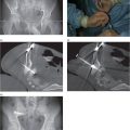
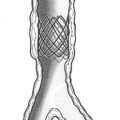
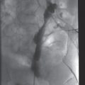
Stay updated, free articles. Join our Telegram channel

Full access? Get Clinical Tree


