Classification
Cancer of the head and neck, which includes cancers of the larynx, nasal passages and nose, oral cavity, pharynx, salivary glands, buccal regions, and thyroid, is the sixth most frequent cancer worldwide. Neck masses can be grouped into two major types: nodal masses and nonnodal masses. Both types can appear as benign or malignant lesions. Most malignant nonnodal masses are epithelial malignancies of the mucous membranes of the upper aerodigestive tract, known as head and neck squamous cell carcinoma (SCC). A second major group of head and neck nonnodal masses arises from the glandular tissue, including thyroid and salivary glands. Less frequent head and neck nonnodal neoplasms include soft tissue and bone tumors (e.g., sarcomas), neuroectodermal tissue tumors (e.g., paragangliomas, malignant melanomas), and skin cancer (e.g., SCC, basal cell carcinoma).
Epidemiology
Chronic consumption of alcoholic beverages and smoking are accepted risk factors for head and neck cancer. In the upper aerodigestive tract, local morphologic, metabolic, and functional alterations lead to increased susceptibility to carcinogens and cell proliferation in the mucosa, resulting in genetic changes with the development of dysplasia, leukoplasia, and carcinoma. Also, radiation exposure is an established environmental factor for the development of glandular neoplasia.
Nodal masses in the head and neck result from regional metastases of malignant lesions of the head and neck or represent reactive enlargement due to inflammatory lesions or benign neoplasms. Lymphoma of the head and neck also presents with enlarged nodes. Cervical node metastases have variable incidence rates, and their presence is associated with a decrease in global survival to roughly half of affected patients; in addition, they are associated with higher recurrence rates.
Normal Anatomy
Gross Anatomy
The neck is composed of the posteriorly located nucha and the anteriorly located cervix. The nucha consists primarily of the vertebral column and its associated musculature, and the cervix (which also means “neck”) can be thought of as a cylinder of soft tissue whose superior extent is a line connecting the occiput and the tip of the chin and whose inferior extent parallels the course of the first rib at the thoracic inlet.
Muscles and Bones.
The most important landmarks to be grossly identified when one is studying the neck in any plane are the sternocleidomastoid muscle and the hyoid bone. The sternocleidomastoid muscle takes its origin from the mastoid tip and digastric notch at the skull base and extends anteriorly, inferiorly, and medially on each side to insert as two heads on the medial third of the clavicle and the manubrium. The course of the sternocleidomastoid muscle divides the soft tissues of the neck into two paired spaces, the anterior triangles and the posterior triangles (one on each side) ( Fig. 24-1 ). All structures located anterior to the sternocleidomastoid muscle lie within the anterior triangles, and structures deep and posterior to it are in the posterior triangles. The anterior triangles have a common side abutting each other in the midline, and their superior border is the mandible. The hyoid bone divides these triangles into a suprahyoid portion and an infrahyoid portion. The suprahyoid division contains the laterally located submandibular triangles and the medially located submental triangle. Superiorly these triangles are separated from the oral cavity by the mylohyoid muscle. By definition, structures above the mylohyoid muscle are in the oral cavity; those below are in the neck.

The base of each submandibular triangle is formed by the body of the mandible. The other two sides of each submandibular triangle are formed by the anterior and posterior bellies of the digastric muscle. The digastric muscle takes its origin from a depression on the skull base between the mastoid tip and the styloid process known as the digastric notch. The posterior belly of the digastric muscle extends anteriorly, inferiorly, and medially from the digastric notch to the greater cornu of the hyoid bone. The anterior belly of the digastric muscle extends from the greater cornu anteriorly, superiorly, and medially to insert on the internal surface of the mandible inferior to the attachment of the mylohyoid muscle. The base of the submental triangle is formed by the hyoid bone. The other two sides of the submental triangle are formed by the anterior bellies of the digastric muscles.
The infrahyoid division of each anterior triangle is divided by the superior belly of the omohyoid muscle into two parts, the carotid triangle superolaterally and the muscular triangle inferomedially. The infrahyoid portion of the anterior triangle contains the larynx, hypopharynx, trachea, esophagus, lymph nodes, and thyroid and parathyroid glands.
The two sides of each posterior triangle are the sternocleidomastoid muscle anteriorly and the trapezius muscle posteriorly. The base of each triangle is formed by the clavicle. The inferior belly of the omohyoid muscle crosses the inferior aspect of the posterior triangle and divides it into two unequal parts, the occipital triangle superiorly and the subclavian triangle inferiorly. The major structures located within the occipital triangle are the spinal accessory nerve (cranial nerve XI) and its associated chain of lymph nodes. The major structures located within the subclavian triangle are the transverse cervical vessels and their associated chain of lymph nodes.
Fasciae and Spaces of the Neck.
Interest in the fasciae of the neck stems from early anatomic investigations performed by surgeons who were seeking ways to predict the spread of infection. The importance of the fasciae of the neck lies in their ability to limit the spread of infections and some tumors.
There is no consistent definition of what constitutes fascia, so there are varied descriptions of the anatomic boundaries of the fasciae ( Figs. 24-2 and 24-3 ). Traditionally there are two major cervical fasciae, the superficial cervical fascia (SCF) and the deep cervical fascia (DCF).


Superficial cervical fascia.
The SCF is a layer of fatty loose connective tissue that covers the head, face, and neck and contains the thin platysma muscles, the muscles of facial expression, the subcutaneous nerves and lymphatics, and portions of the anterior and external jugular veins. Its primary function is to allow the skin to glide easily over the deeper structures of the neck. Infections that track along the SCF are often secondary to skin infections and rarely track deeper into the neck.
Deep cervical fascia.
The DCF is made up of thinner but denser, better-defined layers and extends in the neck below the skull base and encloses the muscles of the neck, the mandible, and the muscles of mastication and deglutition. It consists of three layers: (1) the superficial (or investing) layer (SLDCF) surrounding all the important structures of the neck; (2) the middle layer, with the pretracheal and visceral layers (MLDCF) surrounding the aerodigestive tract; and (3) the deep layer (DLDCF) surrounding the vertebral column and paravertebral muscles. The DLDCF has two divisions separated by a potential space: the alar layer anteriorly and the prevertebral layer posteriorly. All three layers are closely associated in the anterolateral neck, where they contribute to the formation of the carotid sheath, which surrounds the carotid artery, internal jugular vein, and vagus nerve.
Superficial layer of the deep cervical fascia.
The SLDCF is attached posteriorly to the ligamentum nuchae and the spinous processes of the cervical vertebrae. As it extends anteriorly the fascia splits to envelop the trapezius and sternocleidomastoid muscles, crossing the posterior triangle of the neck. In the suprahyoid neck, the SLDCF passes over the muscles below the floor of the mouth, splits to surround the submandibular glands, and when it reaches the mandible, divides into superficial and deep leaflets that enclose the muscles of mastication and form the masticator space. The SLDCF is attached superiorly to the external occipital protuberance, mastoid process, and skull base.
In the infrahyoid neck, the SLDCF encircles the strap muscles (sternothyroid, sternohyoid, and thyrohyoid muscles) anterior to the larynx and trachea (although some authors believe this fascia is part of the MLDCF). The fascia also invests the omohyoid muscle, holding the muscle close to the clavicle so that contraction of the muscle results in a downward rather than a lateral pull on the hyoid bone. Caudally in the midline the SLDCF splits into two layers enclosing the manubrium. This creates the variably sized suprasternal space of Burns (or Gruber), which contains fat and a communicating vein between the left and right anterior jugular veins. If this space is entered during a tracheostomy, inadvertent transection of the communicating vein may result in considerable blood loss. Caudally the SLDCF is attached into the pectoral and axillary regions.
Middle layer of the deep cervical fascia.
The MLDCF is the most arbitrarily described of the fascial layers. The MLDCF in the infrahyoid neck is most commonly considered the fascia between the sternocleidomastoid muscles, passing behind the strap muscles and lying in front of the thyroid gland and trachea (many authors consider this loose connective tissue about the trachea and thyroid gland not to be part of the MLDCF). The deepest portion of the MLDCF is closely adherent to the muscular walls of the pharynx and esophagus and extends ventrally via the pterygomandibular raphe over the buccinator muscles (buccopharyngeal fascia). Inferiorly the MLDCF extends behind the sternum into the origin of the strap muscles and fuses into the fibrous pericardium (at about the level of the fourth thoracic vertebra), forming the anterior border of the retropharyngeal space. Cranially the MLDCF fuses with the thyroid cartilage and the hyoid bone, and laterally it contributes to the carotid sheath on either side of the neck.
The MLDCF in the suprahyoid neck extends from the skull base and follows the outer surface of the pharyngobasilar fascia (cranial continuation of the superior pharyngeal constrictor muscle) and the pharyngeal constrictors. Here the fascia is firmly adherent to the muscular wall of pharynx and esophagus, although some authors argue for the existence of a potential visceral space between the fascia and the viscera.
Deep layer of the deep cervical fascia.
The DLDCF, like the SLDCF, begins in the posterior midline and extends to the side, covering and investing the muscles that form the floor of the posterior triangle. The deep layer is attached laterally to the posterior tubercles of the transverse processes of the vertebrae, where it splits into the anterior alar and posterior prevertebral layers as they extend anterior to the vertebral body (between them lies a layer of loose connective tissue). The alar and prevertebral layers have different craniocaudal extensions. Although both attach superiorly at the skull base, the alar layer blends with the visceral layer along the posterior margin of the esophagus at the level between the sixth cervical and fourth thoracic vertebrae; the prevertebral layer extends from the skull base to the coccyx. The proximal portion of each phrenic nerve lies deep to the prevertebral fascia on the anterior face of each anterior scalene muscle. On each side of the neck, the DLDCF extends laterally from the transverse process of the seventh cervical vertebra, covers the dome of the pleura, and attaches to the rib medially. This fascia separates the lower neck from the thorax and is called Sibson’s fascia.
Neck spaces.
The three layers of the DCF delineate spaces in and through which bacterial infections can spread in the infrahyoid neck.
Visceral space.
The visceral space includes all structures within the confines of the MLDCF (pharynx, cervical esophagus, trachea, thyroid gland, parathyroid glands, larynx, recurrent laryngeal nerves, and portions of the sympathetic trunk) and is continuous with the anterior mediastinum. It is considered to have two subdivisions: an anterior pretracheal space and a more posterior retrovisceral space (see later), which communicate freely around the sides of the larynx, the lowermost pharynx, and the upper cervical esophagus between the levels of the thyroid cartilage and the inferior thyroid artery. Caudal to this level, the pretracheal space is separated from the retrovisceral space by dense connective tissue. The posterior margin of the retrovisceral space is the alar layer of the DLDCF.
Retropharyngeal space.
The retropharyngeal space is situated in the midline directly posterior to the pharynx. The anterior boundary of the retropharyngeal space is formed by the MLDCF fascia, and the posterior boundary is formed by the DLDCF. The retropharyngeal space can be further divided by the alar layer of the DLDCF into the retrovisceral space anteriorly and the danger space posteriorly. Depending on its location, infection in the retropharyngeal space can extend inferiorly in the retrovisceral and pretracheal space (it is common that a retropharyngeal abscess can affect the thyroid gland and anterior mediastinum) to the level of approximately C7 (where the alar layer and the visceral layer fuse) or in the danger space just above the level of the diaphragm, where the fused alar and visceral fasciae fuse with the prevertebral fascia. Because the danger space is a closed one, the infection must penetrate its walls to enter the space. Because it is impossible to separate these two smaller spaces radiographically, the retropharyngeal space may be considered a single radiographic space, with the recognition that all infections in the retropharyngeal space must be evaluated in full, and scans of either the superior mediastinum or entire chest may be necessary ( Fig. 24-4 ).

Prevertebral space.
The vertebral space is a potential space that includes those structures (vertebral bodies, paravertebral and scalene muscles, vertebral arteries) that are surrounded by the DLDCF. Infections of the prevertebral space are usually secondary to vertebral infection (osteomyelitis) or posterior extension arising in the retropharyngeal space. The vast majority of the pathology that affects this space arises from the adjacent vertebral bodies, disks, and nerves.
Carotid space.
The carotid space is a potential space within the carotid sheath. Investigators doubt whether this cavity can act as a space that allows spread of infections. Furthermore, because little areolar tissue is present within the sheath, actual infection of the carotid space is rare. The most accepted theory is that the carotid sheath may be a true space only below the carotid bifurcation and above the root of the neck. Similarly there is controversy over whether the carotid sheath in the suprahyoidal neck should be considered a separate “carotid space” or part of the parapharyngeal space. We support the latter opinion, which follows the anatomic and surgical literature. Remarkably the carotid sheath, with its contributions from all three layers of the deep cervical fascia, can act as a conduit of infection from one space to another. Septic or reactive thrombosis of the internal jugular vein may produce swelling within the carotid space. The internal jugular vein and its associated chain of lymph nodes closely parallel the deep surface of the anterior margin of the sternocleidomastoid muscle, thereby bridging the anterior and posterior triangles. The arterial and neural components of the carotid sheath, common carotid artery, internal carotid artery, and vagus nerve also traverse the neck within the anterior triangle.
Body of the mandible.
Another space in the suprahyoid neck is the space of the body of the mandible, which is confined by the deep leaflet of the SLDCF on the lingual surface of the mandible along the line of origin of the mylohyoid muscle and the lingual cortex of the mandible. This potential space is limited anteriorly by the attachment of the anterior belly of the digastric muscle and posteriorly by the attachment of the internal pterygoid muscle.
Submandibular space.
The submandibular space is the uppermost boundary of the neck as it extends from the hyoid bone to the mandible. The mucosa in the floor of the mouth is its cranial border. The space is divided into an upper (sublingual space) and lower portion by the mylohyoid muscle. The portions communicate freely around the dorsal margin of the muscle. The submandibular gland is folded around the back of this muscle, lying partially above and partially below its dorsal edge. The radiologist should also identify whether a tumor is in the sublingual space, because that will eventually lead to an intraoperative sacrifice of the lingual nerve (trigeminal nerve branch that carries the taste fibers of the anterior two thirds of the tongue) and hypoglossal nerve, which runs from the floor of the mouth to the tongue base. Other radiographically important anatomic landmarks of the above-described spaces are the deep portion of the submandibular gland and the submandibular duct (Wharton’s duct) in the sublingual space and the anterior belly of the digastric muscle, the superficial portion of the submandibular gland, and the lymph nodes in the submandibular space. The above-mentioned submental and submandibular triangles of the neck are the superficial landmarks that correspond to the lower portion of the submandibular space.
Sectional Anatomy
The sternocleidomastoid muscle is a constant landmark that can always be identified on axial computed tomography (CT) scans or magnetic resonance imaging (MRI) through the neck. As one progresses from superior to inferior, the location of the sternocleidomastoid muscle moves from a far lateral position to a paramedian position. With this change in position of the sternocleidomastoid muscle, a change in relative sizes of the anterior and posterior triangles can be identified. Superiorly the anterior triangle occupies the majority of the cross-sectional area of the neck because there is little space between the sternocleidomastoid and trapezius muscles. Inferiorly the posterior triangle occupies the majority of the cross-sectional area of the neck because there is little space between the anterior surface of the sternocleidomastoid muscle and the midline.
The mylohyoid muscle, the major landmark separating the oral cavity from the suprahyoid neck, is readily identified on both coronal and axial images. On axial images ( Fig. 24-5A and B ), the muscle appears in cross section as two separate muscle bundles medial to the mandible. As axial images are obtained from superior to inferior, the distance between the separate bundles decreases. The superior aspect of the submandibular gland is identified on axial images at the posterior margin of the mylohyoid muscle. On coronal images, the muscle has the configuration of a hammock suspended from the medial (lingual) surface of the mandible (see Fig. 24-5C and D ). Immediately inferior to the mylohyoid muscle, the anterior bellies of the digastric muscle can be identified ( Fig. 24-6 ). Depending on the degree of angulation used on axial imaging, varying amounts of mylohyoid muscle can be seen projecting between the anterior bellies of the digastric muscle. The posterior belly of the digastric muscle can usually be identified medial and posterior to the parotid gland, separating the gland from the contents of the carotid sheath.


The hyoid bone is the major bony landmark of the anterior neck. The hyoid is best identified on axial CT images, where its central body and greater horns (cornua) appear in the midline as an inverted U approximately at the level of the C3-C4 disk space ( Fig. 24-7 ). The carotid bifurcation is typically located at or near the level of the hyoid bone.

Separation of the larynx into the supraglottis, glottis, and subglottis seems fundamental for the interpretation of scans of patients with laryngeal cancer. The supraglottis includes the false vocal cords, arytenoids, epiglottis, and aryepiglottic folds. The glottis includes the true vocal cords, the anterior and posterior commissures, and the vocal ligament extending from the arytenoid cartilage to the thyroid cartilage. The laryngeal ventricle, which is supposed to separate the supraglottis and glottis, is itself a part of the supraglottis. Finally, the subglottis begins 1 cm below the ventricle and extends to the first tracheal ring.
The thyroid cartilage has an inverted V appearance on axial images ( Fig. 24-8 ). The superior third of the cartilage is not fused in the midline at the level of the thyroid notch. Immediately superficial to the two halves of the thyroid cartilage are the strap muscles. The degree and pattern of ossification of the cartilages vary with the age and sex of the patient. Gross cartilage invasion in laryngeal cancer can be detected with CT, but nonossified hyaline cartilage shows about the same density values as tumor on CT images. Separation of nonossified cartilage from the overlying strap muscles and detection of intracartilaginous alterations is accomplished more easily with MRI than with CT. The superior cornua of the thyroid cartilage are easily identified as paired calcified structures, and the inferior cornua of the thyroid cartilage articulate with the posterior aspect of the cricoid cartilage.

The cricoid cartilage is the only intact ring of the larynx with a complete posterior component and has a variable degree of ossification on axial imaging. In adult patients, the cricoid cartilage appears on CT scans as a thin rim of calcification surrounding a lucent medullary center. On T1-weighted MRI, the cricoid appears as a ring of tissue isointense to fat. The level of the cricoid cartilage also marks the point at which the omohyoid muscle crosses over the internal jugular vein. The cricoarytenoid joint is a readily recognizable structure that demarcates glottic from supraglottic and subglottic structures.
The paraglottic tissues can be separated into the preepiglottic and paraglottic fat (dark on CT scanning) and the thyroarytenoid muscle (soft tissue density on CT and intermediate T1-weighted on MRI) of the true vocal cords. The true vocal cords meet in the midline at the anterior commissure, which should be no more than 1 to 2 mm thick. The posterior commissure refers to the mucosa between the two vocal processes on the anterior surface of the arytenoid cartilage.
At approximately the level of the cricoid cartilage ( Fig. 24-9 ), the superior pole of the thyroid gland appears on axial images as a triangular soft tissue structure situated between the cricoid cartilage medially and the carotid sheath structures laterally. The normal gland (owing to its iodide content) has a density of 80 to 100 Hounsfield units (HU) on CT. A homogeneous gland on noncontrast CT correlates well with thyroid function. The gland enhances diffusely after application of iodinated intravenous contrast material. The latter can alter the radioactive iodine uptake measurements (i.e., in nuclear imaging) for up to 6 weeks following the application. This alteration does not happen after gadolinium application. On noncontrast T1-weighted images, the gland is homogeneous in appearance and slightly hyperintense to skeletal muscle. On T2-weighted imaging, the gland is hyperintense relative to the neck musculature. Axial and sagittal T1- and T2-weighted images (with fat saturation) as well as postcontrast axial fat-saturated T1-weighted images are essential for MRI of the thyroid and parathyroid glands.

The posterior triangle of the normal supracricoid neck appears as a fat-filled cleft containing a few small soft tissue structures representing nutrient vessels, lymph nodes, and nerves. Beginning at the level of the cricoid cartilage, the anterior scalene muscle can be identified in the medial aspect of the posterior triangle, posterior to the carotid sheath structures. The anterior scalene muscle, which arises from the transverse processes of C4-C6, is the key reference point needed to locate the major neural and vascular structures in the region. The subclavian vein is located anterior to the muscle that divides the subclavian artery in three anatomic portions. The phrenic and vagus nerves cross the root of the neck anterior to the first portion of the subclavian artery laterally and medially of it, respectively. The anterior scalene muscle lies directly anterior to the exiting trunks of the brachial plexus. At the level of the first tracheal ring, the brachial plexus is identified as a heterogeneous low-density or low-signal-intensity focus immediately posterior to the anterior scalene muscle.
Nodal Anatomy
Forty percent of the body’s lymph nodes are located in the head and neck region, which represents about 20% of the body’s volume. Each lymph node is enclosed by a fibrous capsule, and lymph moves into a node via several lymphatic vessels and emerges by one or two efferent vessels. Fibrous septa (trabeculae) extend from the covering capsule toward the center of the node. Cortical nodules found within the sinuses along the outer region of the node are separated from each other by these trabeculae. The center, or medulla, of a lymph node is composed of sinuses and cords. Both the cortical and medullary sinuses are lined with specialized reticuloendothelial cells (fixed macrophages) capable of phagocytosis. When the lymph nodes elicit the immune response, the nodes enlarge (reactive hyperplasia). However, the morphologic analysis of the reactivity has a controversial prognostic value, probably owing to a variety of response patterns in an individual patient as well as in an individual node. Nodes that drain areas of frequent infection (e.g., jugulodigastric or submental nodes) tend to enlarge over many years relative to other cervical nodes.
Normal lymph nodes have an elliptical shape whose long axis is directed parallel to the anatomic structures along which the nodes are distributed and thus cannot be shown in axial CT slices. The ratio of the longitudinal (maximum) diameter to the transverse (minimum) diameter of a lymph node is a major morphologic criterion for assessing metastatic disease. In addition the minimum diameter more closely correlates with the volume of the lymph node and is less dependent on the scan plane, and therefore it is useful for follow-up imaging. The CT attenuation of lymph nodes on noncontrast CT scans is equivalent to that of other soft tissue structures. The node hilum can sometimes be seen to contain a small amount of fat. Normal lymph nodes display moderate homogeneous enhancement following intravenous injection of contrast material.
On MRI, lymph nodes appear homogeneous with low to intermediate precontrast T1-weighted intensity and appear at fairly high intensity in high-resolution T2-weighted images. Moreover, lymph nodes have smooth noninfiltrating margins and a slight homogeneous enhancement after gadolinium administration. High-resolution MR microimaging offers a detailed structural analysis of the nodes using microscopy coils and demonstrating medullary sinus as regions of low signal intensity and follicles as high-intensity structures; the method can effectively characterize the morphologic details of benign and metastatic nodes without using gadolinium enhancement. Nevertheless, microimaging is limited to the superficial nodes and requires additional time for examination and evaluation of the imaging data.
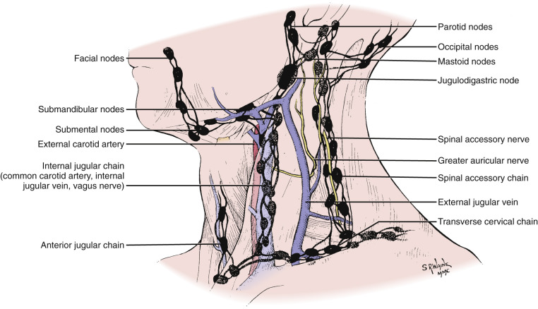
Classification.
As the pathways of node metastasis were recognized in the last century, the necessity of a nodal classification that identifies the precise location of the nodes emerged. This is important because neoplastic lymph nodes are mainly regionally localized according to the sentinel lymph node concept. The most commonly used classification of Rouvìere in 1938, mainly based on the superficial triangles of the neck ( Fig. 24-10 ), was followed by that of Shah and colleagues in 1981 ( Fig. 24-11 ), which employed a simpler level-based system to help the surgeon select the most appropriate type of nodal resection. The latter system can be easily transferred to the axial imaging ( Fig. 24-12 ). Since then, further classifications such as that of the American Joint Committee on Cancer (AJCC) in 1997 and the American Academy of Otolaryngology—Head and Neck Surgery (AAO-HNS) have modified and improved the initial level-based system. To address specific issues raised in both the AJCC and AAO-HNS classifications and to bring to nodal classification the anatomic detail and reproducibility of imaging the vast majority of patients currently receive, an imaging-based (CT and MRI) classification was suggested in 1999. A brief presentation of this classification is given in Box 24-1 .


- I
Submental and submandibular nodes, located above the hyoid bone, below the mylohyoid muscle, and anterior to the back of the submandibular gland
- Ia
Submental nodes
- Ib
Submandibular nodes
- Ia
- II
Upper internal jugular nodes, lying from the skull base to the level of the bottom of the body of the hyoid bone, posterior to the back of the submandibular gland, and anterior to the back of the sternocleidomastoid muscle
- IIa
Nodes anterior, medial, lateral, and posterior to the internal jugular vein
- IIb
Nodes posterior to the jugular vein, with a fat plane separating them from the vein
- IIa
- III
Midjugular nodes, located from the level of the bottom of the hyoid bone to the level of the bottom of the cricoid arch, anterior to the back of the sternocleidomastoid muscle
- IV
Low jugular nodes, lying from the level of the bottom of the cricoid arch to the level of the clavicle, lateral to the carotid arteries
- V
Nodes in the posterior triangle, lying posterior to the back of the sternocleidomastoid muscle from the skull base to the level of the bottom of the body of the cricoid arch and posterior to a line connecting the back of the sternocleidomastoid muscle and the posterolateral margin of the anterior scalene muscle from the level of the bottom of the cricoid arch to the level of the clavicle. They also lie anterior to the anterior edge of the trapezius muscle.
- Va
Upper level V nodes, located from the skull base to the level of the bottom of the body of the cricoid arch
- Vb
Lower level V nodes, located from the level of the bottom of the cricoid arch to the level of the clavicle.
- Va
- VI
Upper visceral nodes, lying between the carotid arteries from the level of the bottom of the hyoid bone to the level of the top of the manubrium
- VII
Superior mediastinal nodes, lying between the carotid arteries from the level of the top of the manubrium to the level of the innominate vein
Supraclavicular nodes lie at or caudal to the clavicles and lateral to the carotid artery.
Retropharyngeal nodes lie within 2 cm of the skull base, medial to the internal carotid arteries.
Imaging Techniques
Various imaging techniques are currently used in the evaluation of patients with neck masses before, during, and after treatment. Each of these imaging modalities has its own advantages and disadvantages. In most patients, especially in developed countries, CT and MRI are performed for diagnosing and staging of neck masses. In the pediatric population, ultrasonography has a special role in follow-up of nodal masses. Whether CT or MRI is the primary imaging modality depends on the institution, although head and neck radiologists tend to use CT for imaging of laryngeal cancer, hypopharyngeal cancer, oropharyngeal cancer, and inflammatory lesions and also use it to complement the diagnostic evaluation of tumors with presumed bone destruction. The relative low cost of CT examinations, its wide availability, the short examination time, and the high-quality multiplanar imaging provided, as well as the higher sensitivity and specificity regarding nodal involvement in malignant neoplasms, are indisputable advantages of CT over MRI. On the other hand, the relatively low soft tissue contrast resolution of CT, the need to administer iodinated contrast agents, and the severe image quality degradation caused by dental fillings and other foreign objects are disadvantages of CT imaging. MRI in turn may be jeopardized by motion artifacts and orthodontic material. Whatever the admission imaging modality, the patient’s follow-up has to be performed with the same modality and the same examination protocol.
Computed Tomography
CT may be regarded as the workhorse of head and neck imaging. There are many types of CT scanners, most of which are multislice units. Thus it is not possible to define the optimal protocol. The ideal neck CT scan provides the best possible contrast of soft tissue (with the choice of an appropriate delay, contrast agent volume, flow rate, and scanning time), allows visualization of the arterial and venous vascular structures, and provides thin multiplanar reconstructions in soft tissue and bone algorithms in an angle appropriate for evaluation of the suspected lesion. CT is performed with the patient supine on the scanner gantry and during quiet respiration. The patient’s head may be cushioned to avoid motion artifacts during the hot flush of contrast agent injection. The patient’s shoulders must be dropped as low as possible. In case of incremental or single spiral CT, malposition of the patient can cause artifacts that simulate disease. One common solution is to acquire images from the superior orbital rim to the hard palate with the use of gantry angulation parallel to the central skull base. Images from the alveolar ridge of the mandible to the lung apex are then obtained with a gantry angulation parallel to the body of the mandible. If the patient’s chin is fully extended, this latter series may be obtained with a 0-degree gantry angulation.
Intravenous contrast enhancement is essential for CT examinations to facilitate both tissue characterization of neck masses and separation of neck masses from normal vascular structures. Most investigators recommend a bolus of approximately 80 to 100 mL of high-density iodinated contrast material administered at a rate of 1 to 2 mL/sec and a delay of 80 to 100 sec before image acquisition, followed by a steady rapid-drip saline infusion at the same rate. Power injectors, commonly used for abdominal or thoracic CT scanning, can be readily adapted for neck CT examinations.
When evaluating the neck, contiguous 5-mm-thick axial images are usually obtained from the level of the superior orbital rim to the lung apex (scanning from cranial to caudal) to reduce artifacts at the level of the thoracic inlet caused by the beam-hardening effects of the contrast agent. The field of view must be as small as possible to enhance the spatial resolution (reconstruction of the raw data in a greater field of view can be subsequently performed to encounter possible pathologic conditions in these regions). The images are reconstructed in 3-mm slices for evaluation of the oropharynx (parallel to the hard palate on the axial section and coronal to the mouth floor) and 2-mm slices for evaluation of the hypopharyngeal-laryngeal region (parallel to the vocal cords as well as vertical to them). In cases of extended osteolytic lesions, three-dimensional (3D) imaging provides valuable information to surgeons.
A significant advantage of the fast image acquisition of multislice CT scanners is the easier performance of a dynamic maneuver during the examination. Such maneuvers are the [i]-phonation (for better visualization of the laryngeal ventricle) and the modified Valsalva (for better visualization of the pyriform sinuses, postcricoid region, and gingivobuccal tumors).
CT imaging techniques that can complement the standard CT study include dynamic acquisition of neck mass sections during administration of the bolus of contrast agent. The morphologic information obtained by cross-sectional imaging of SCC of the upper aerodigestive tract is often insufficient because of the highly infiltrative character of the tumor, posttherapy edema or fibrosis, and the difficulty of reliably recognizing lymph node metastases in apparently “normal” lymph nodes. Perfusion CT, based on various tracer kinetic models, aims at measurement of tissue blood supply, tissue vascularity, and contrast clearance. Because every neoplasm is characterized by neovascularity and increased angiogenic activity, perfusion CT is a potential imaging tool of tumor activity, theoretically before the tumor proceeds in a gross anatomic distortion.
Magnetic Resonance Imaging
MRI of the neck is routinely performed at magnetic fields of 1.5 tesla (T) and recently at 3.0 T. Possibly more important than field strength is the choice of the right surface coils and their optimal positioning, along with comfortable positioning of the patient and instructions to avoid any movement, coughing, and swallowing during the examination. Usually the choice of the appropriate coil depends on the specific organ or lesion being imaged; however, in our opinion the combined head-neck coil should be used every time a neck MRI study is performed. This ensures a comprehensive evaluation of the entire extracranial head and neck—evaluating all nodal masses, a second primary neoplasm, and perineural tumor spread. The possible drawback of inhomogeneous recipient field characteristics at the crossover between the two coils is of minor importance and can be partially overcome by shimming—improved coils with identical receiver coil elements—and sequences with short echo trains.
A conventional MR survey is performed using a dedicated head-and-neck circular polarization surface coil and (at the beginning) performing a localizer in three planes. The axial plane is aligned along the patient’s hard palate which in turn has to be perpendicular to the tabletop. The slices should be 3 to 4 mm with either no interslice gap or a 10% interslice gap. The entire neck should be studied to evaluate lymphadenopathy, especially in patients with esophageal or thyroid cancer who present with superior mediastinal node metastases. The field of view may be approximately 20 to 22 cm and the matrix, if possible, 512 × 512 (256 × 256) pixels. Inversion recovery fast-spin echo (FSE) sequences with fat saturation (spectral presaturation by inversion recovery [SPIR], spectral selection attenuated inversion recovery [SPAIR], and turbo inversion recovery magnitude [TIRM]) have proven useful in imaging lymph nodes by improving the conspicuity of small nodes adjacent to or surrounded by fat. Alternatively, contrast can be improved by performing the sequence with a chemical shift selective suppression (CHESS) technique. The FSE inversion recovery sequence can be complementary, followed by an FSE T2-weighted sequence (preferably on the axial plane). Subsequently, axial and coronal spin echo T1-weighted images are performed before and after application of gadolinium-containing contrast agent with a fat saturation in the postcontrast axial sections. Another fat saturation in the coronal plane can be renounced because the saturated images are prone to susceptibility artifacts and have a long acquisition time. Finally, the radiologist ought to avoid very fast imaging using single-shot techniques and instead take advantage of parallel imaging in high-field scanners.
In addition to conventional contrast-enhanced MRI, axial diffusion-weighted imaging (DWI) may be also performed. DWI allows visualization as well as separation of molecular diffusion from microcirculation of the blood in the capillary network (perfusion) of biological tissues. Neoplasms are associated with alterations in water diffusivity and microcirculation of the node. DWI can be obtained with a single-shot echo planar imaging (EPI) sequence by using the same coil. The sequence can be repeated for at least three values of the motion-probing gradients (usually b = 0, 500, 700, or 1000 sec/mm 2 ). Suggested section thickness is 4 to 5 mm with an intersection gap of 1 mm. Scanning time does not usually exceed 2 minutes. Quantification of diffusion abnormalities requires calculation of the apparent diffusion coefficient (ADC).
Another promising MRI technique is proton magnetic resonance spectroscopy (MRS), wherein data can be acquired on the same scanner and with the same coils that were used for the imaging. The MRI examination is used for localizing the MRS. Single-voxel spin echo sequence may be used. The echo time (TE) allows in-phase detection of the choline signal. Weak water suppression can be achieved by a CHESS technique. The volume of interest (VOI) fits the size of the suspected lesion. Automatic shimming of the system is usually applied and controlled by interactive shimming by the radiologist. Postprocessing of the data includes identification of choline and creatine metabolites.
Similar to perfusion CT, dynamic MRI offers the potential of visualizing dynamically the tumor vascularity, including permeability disorders with indirect implications for tissue oxygenation status. EPI or a VIBE (volumetric interpolated breath-hold imaging) sequence may be used. For postprocessing of the acquired data, a semiquantitative analysis using mean signal intensity versus time curves may be performed. Parameters such as peak time (in seconds), peak enhancement (% baseline), and washout slope estimate can be calculated from the late point versus the peak point. Another approach uses commercially available deconvolution-based analysis of the dynamic data, which were first used in perfusion studies of the brain.
MRI also enables contrast material–enhanced intravenous lymphography. The first contrast medium used for intravenous lymphography was dextran-coated ultrasmall superparamagnetic iron oxide (USPIO) particles, which accumulate slowly in the phagocytes of the lymph nodes. Based on the T2* effects of the iron oxide particles, after a single intravenous administration of USPIO, T2-weighted images show areas of focal signal intensity loss in medullary sinuses corresponding to the distribution of uptake by macrophages. Lymph follicles appear unchanged in signal intensity because they are largely devoid of macrophages. Infiltration of lymph nodes with tumor alters the architecture, with tumor replacing the macrophages; hence the nodes retain their high signal intensity after USPIO administration. Several studies have demonstrated enhanced sensitivity and specificity for lymph node evaluation after administration of USPIO particles for head and neck malignancies. However, very small lesions may go undetected because of the “blooming effect,” which reflects the extreme sensitivity of T2*-weighted imaging to susceptibility artifacts. Other pitfalls of the method include the poor contrast of T2- and T2*-weighted imaging between a subcapsular node metastasis and the surrounding extralymphatic tissue.
Another promising lymph node–specific contrast agent is gadofluorine M (T1 contrast agent). Gadofluorine M is a water-soluble paramagnetic gadolinium-based agent whose mechanism of lymph node uptake is presumed to be direct transcapillary passage through interendothelial junctions into medullary sinuses.
Related posts:
Stay updated, free articles. Join our Telegram channel

Full access? Get Clinical Tree


