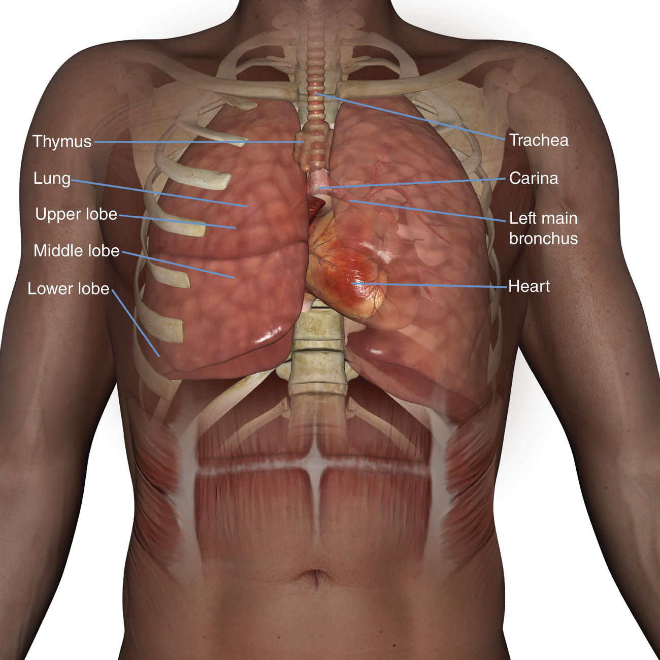
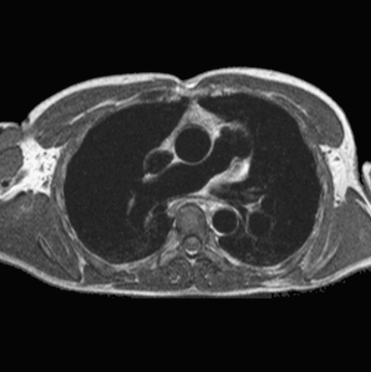
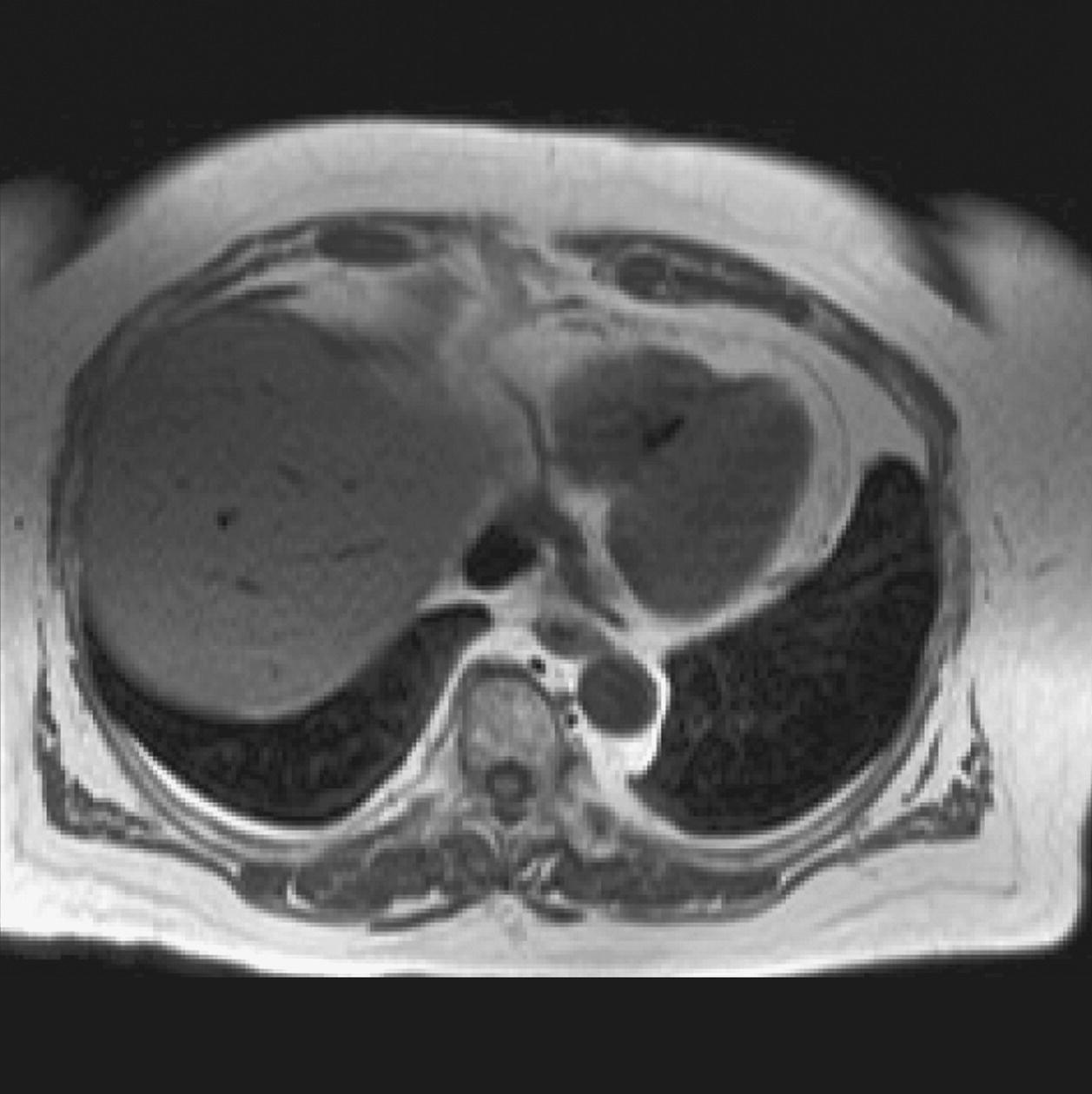
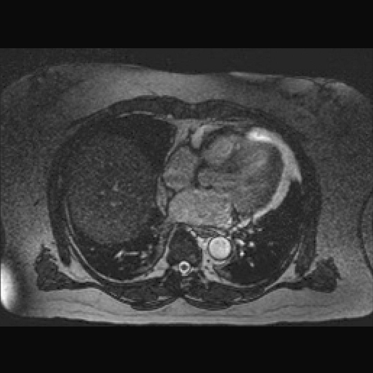
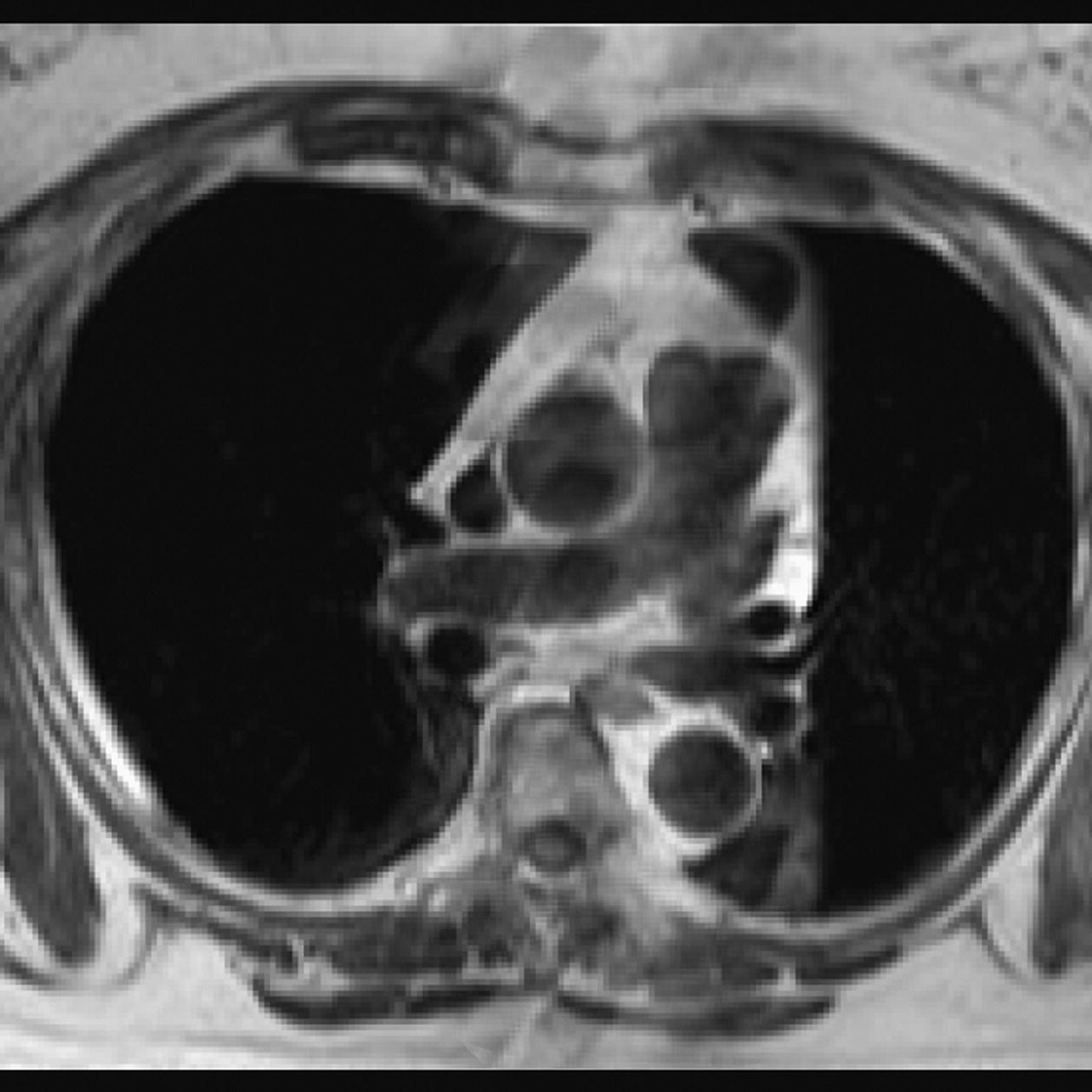
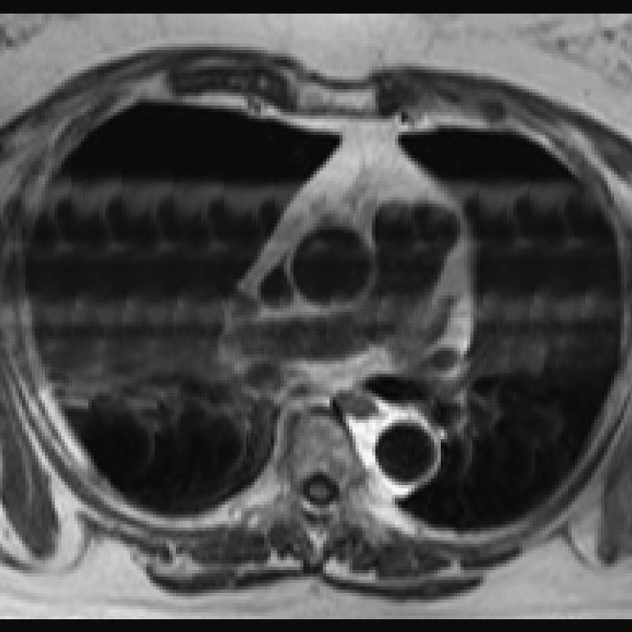
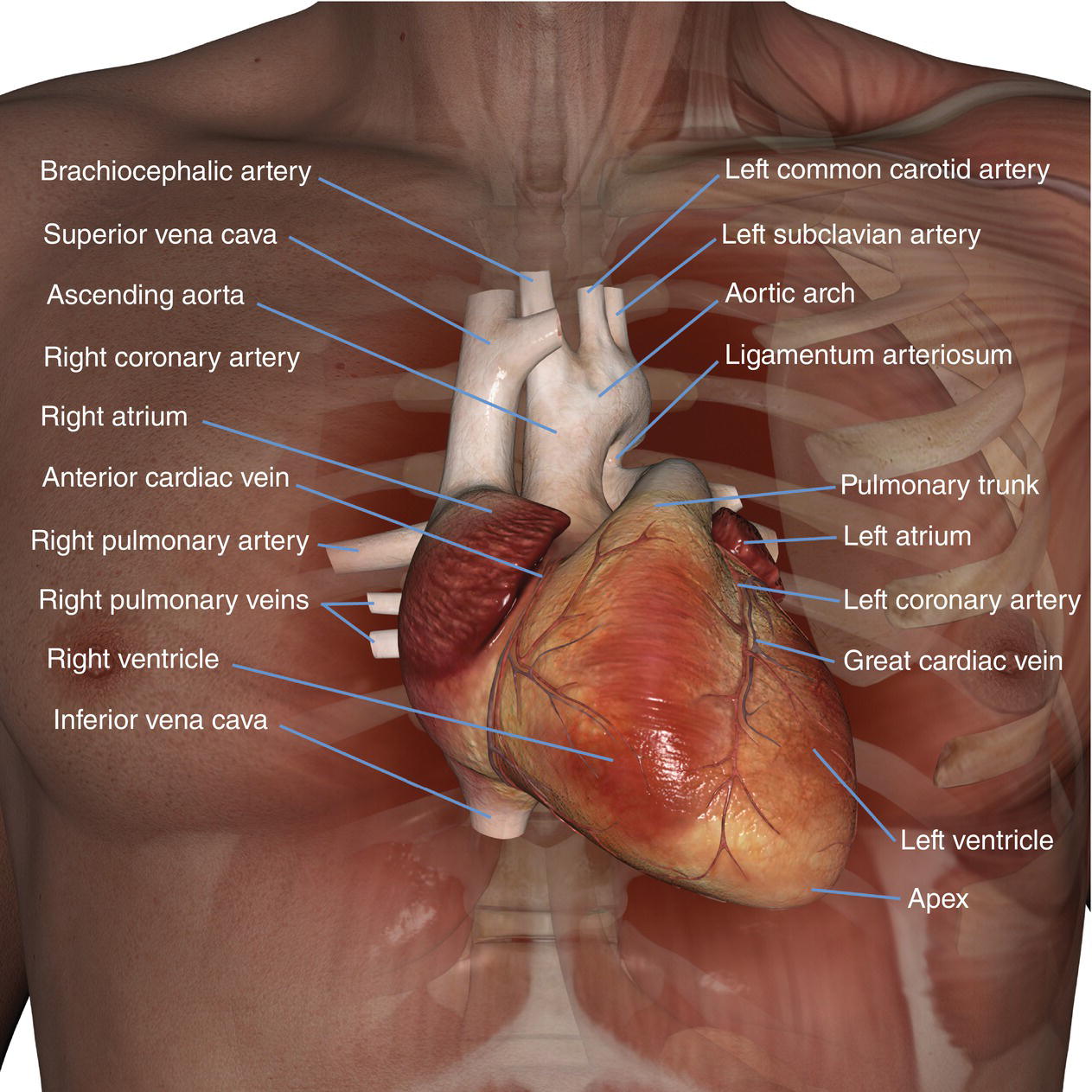
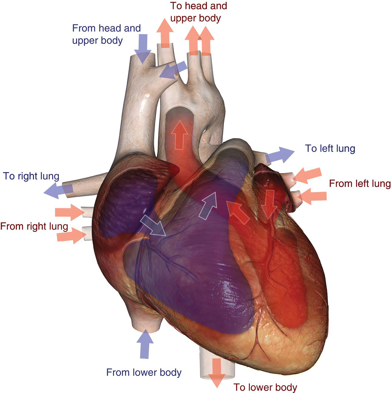
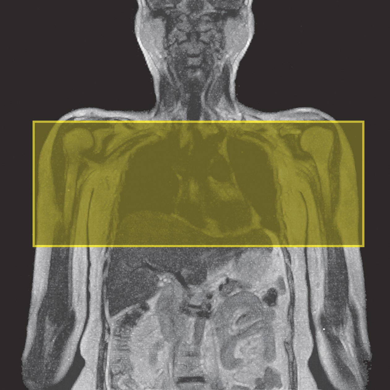
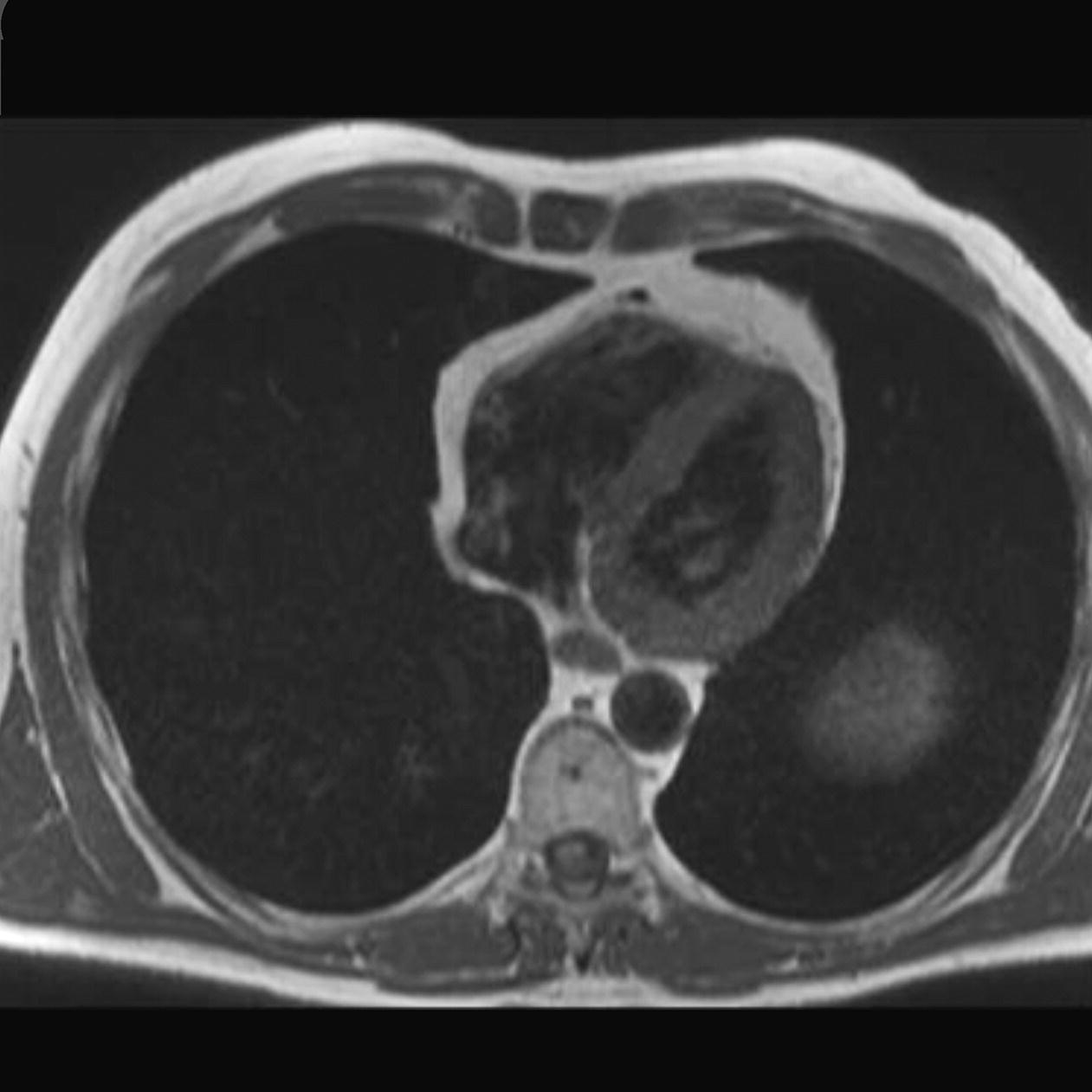
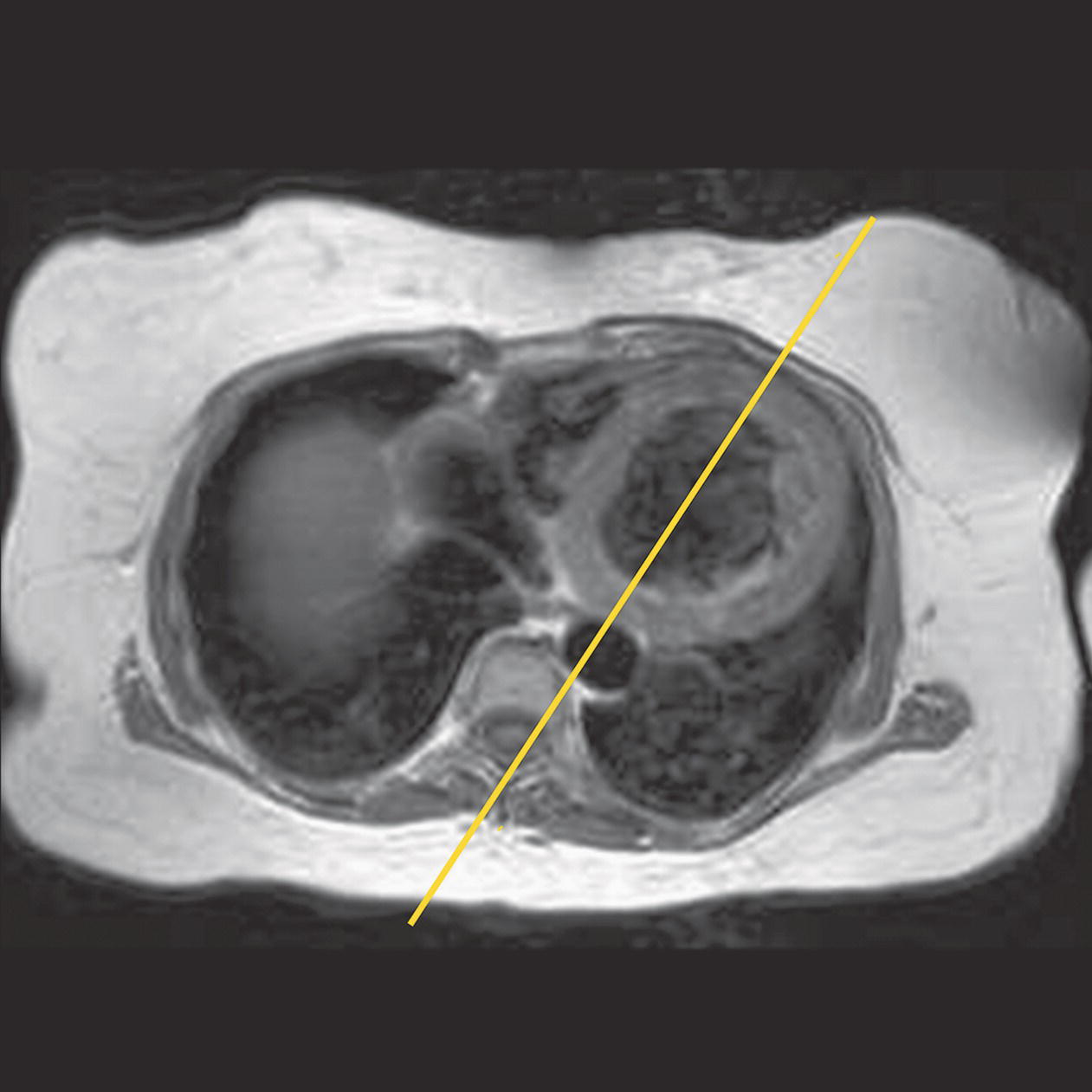
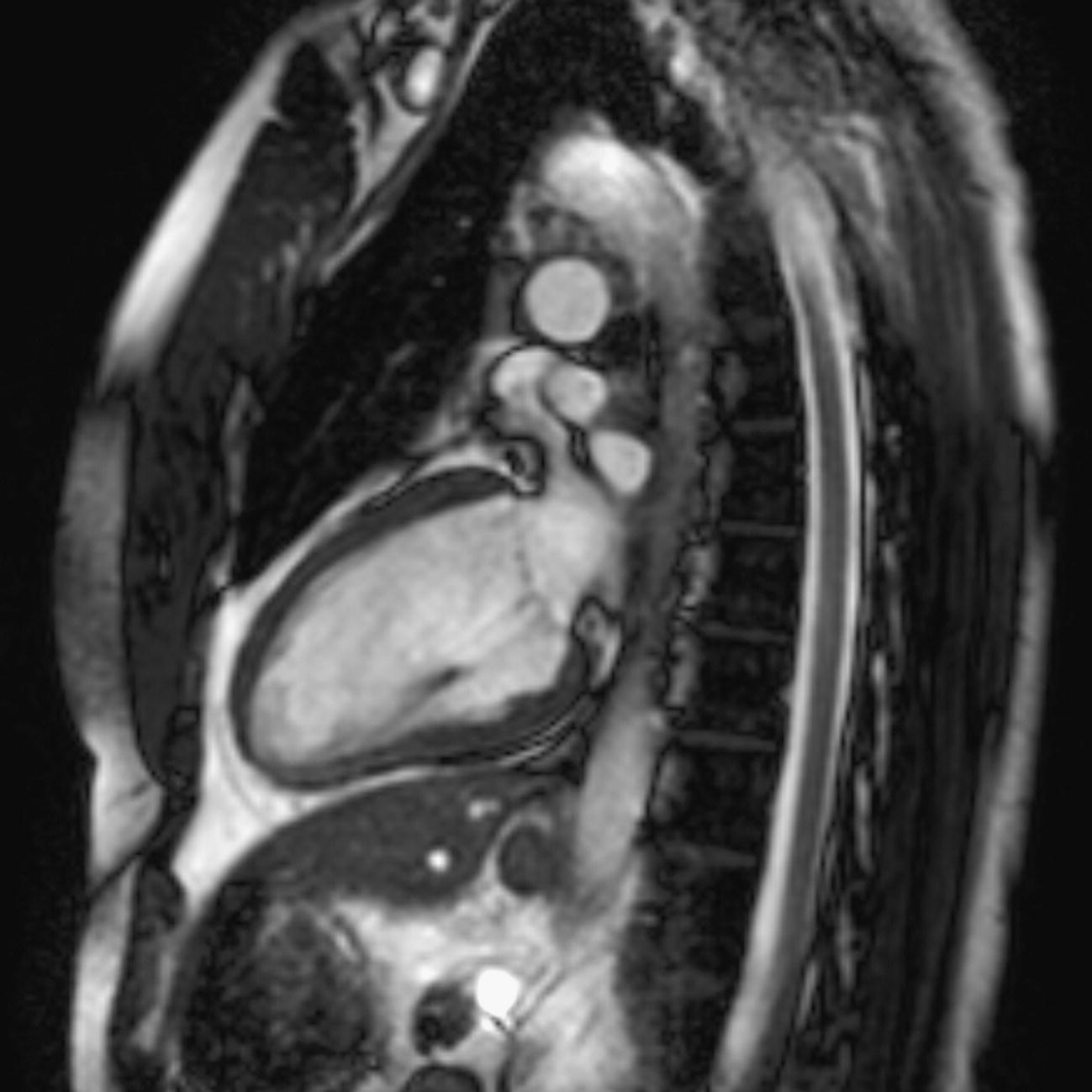
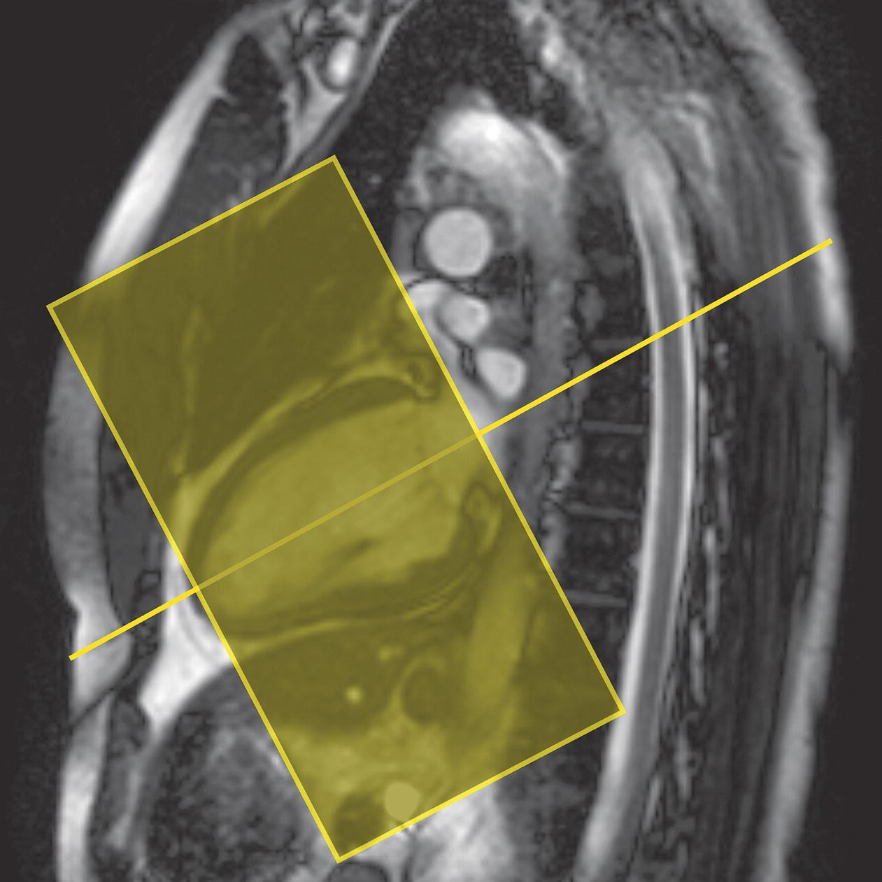
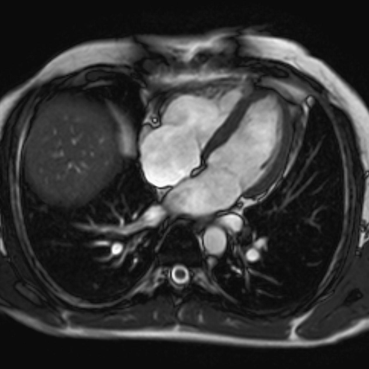
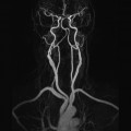
10 Table 10.1 Summary of parameters The figures given are for 1.5 T and 3 T systems. Parameters are dependent on field strength and may need adjustment for very low or very high field systems. Figure 10.1 Anterior view of the components of the chest cavity. The patient lies supine on the examination couch with the RC bellows (if required) and ECG gating leads attached. Pads can be placed under the patient’s knees (for comfort) and beside the patient’s elbows (for optimal MR imaging). In some cases, if the patient is not comfortable supine and/or if the patient has trouble in confined spaces, prone positioning may be a suitable alternative. The patient is positioned so that the longitudinal alignment light lies in the midline, and the horizontal alignment light passes through the level of the fourth thoracic vertebra, or the nipples. The patient can be placed feet first into the magnet if the ECG trace is unsatisfactory as this changes the patient’s polarity relative to the main field (see Gating and respiratory compensation techniques in Part 1). Figure 10.2 Coronal breath-hold incoherent (spoiled) GRE T1 of the chest showing prescription of axial slices. Acts as a localizer if three-plane localization is unavailable, or as a diagnostic sequence. Medium slices/gaps are prescribed relative to the vertical alignment light, from the posterior chest muscles to the sternum. The entire lung fields from apex to base are included in the image. As the chest anatomy is generally located more anteriorly than posteriorly, slices are offset in the anterior direction. P 60 mm to A 80 mm Figure 10.3 Axial SE T1-weighted gated image of the chest or axial imaging. Figure 10.4 Axial FSE T1-weighted image through the chest showing a large lesion in the left lung. Figure 10.5 Axial incoherent GRE T1. Same slice as Figure 10.4. As for the coronal T1, except slice thickness/gap is adjusted to fit the ROI. Prescribe slices from the diaphragm to the apex of the lung or through the ROI. Figure 10.6 Axial SS-FSE. Same slice as shown in Figure 10.4. Slice prescription as for axial T1. Useful to characterize active tissue such as distinguishing tumour from consolidated lung and to evaluate fluid pneumonia or pleural effusion. Lung perfusion can be evaluated by either administering contrast or with ‘spin tagged perfusion’ techniques. In these cases, contrast is ‘tagged’ with either contrast or arterial spin tagging applied in the midline of the patient in an attempt to saturate blood flowing from the heart and into the lungs by way of the pulmonary arteries. This study is analogous to the VQ scan offered in Nuclear Medicine. The patient breathes in hyper-polarized helium gas and holds their breath while images are acquired. These sequences can be used during respiration to assess motion of the diaphragm. In this case, slices are acquired during normal respiration and replayed as a movie or cine loop. The chest has a relatively poor SNR as the proton density of the lung fields is low. In addition, there is little fat to give good contrast. The implementation of a volume array coil helps maintain SNR. This is especially useful when thinner slices and a finer matrix are required. Chest imaging can be performed with a number of RF coil designs. Although the body coil is notorious for lower SNR, it can be utilized for large areas of coverage. Also, the body coil is acceptable in cases where contrast is the main determining factor in image contrast, such as MRA of the aorta or the pulmonary arteries. For the most part therefore, the body coil will produce optimum images for chest imaging. For higher SNR, higher resolution torso array coils should be used (see Heart and great vessels). The use of multiple NEX/NSA not only reduces some respiratory and cardiac artefact because of signal averaging, but also improves the SNR due to increased data collection. The disadvantage of this strategy is the associated increase in scan time, although this can be compensated for, to some degree, by the implementation of a coarser matrix or a rectangular/asymmetric FOV. SE T1-weighted sequences are traditionally used to show anatomy and black blood. Dark-blood images can be acquired by using the double inversion recovery (DIR) technique to null the signal from blood. DIR sequences can be FSE, in which case each image is acquired in a separate breath-hold, or single shot, in which case multiple images are acquired in one breath-hold. DIR images are always gated to the ECG so that cardiac motion artefact is reduced from the images. GRE sequences are useful for the evaluation of flow, and T2-weighted sequences demonstrate pathology and free fluid. On some systems, FSE is not compatible with RC techniques that use phase reordering. Under these circumstances, SE sequences can be substituted. Fast imaging employing T2 steady-state acquisition sequences should also be considered instead of SS-FSE to image fluid-filled structures in very short acquisition times. Respiratory, cardiac and flow motion are the most obvious artefacts in the chest. Image quality can be compromised by physiologic motion from the lungs and heart, from flowing blood within vessels and, in some cases, from the oesophagus and stomach. Compensation for physiologic motion artefacts in the chest can be reduced by a number of imaging options including respiratory compensation, breath-hold techniques, cardiac gating, cardiac triggering or other imaging options (saturation pulses or gradient moment nulling). Breath-hold techniques are achieved by the acquisition of rapid imaging sequences (20 s or less) and instructing the patient to hold their breath during the image acquisition. Motion artefact will always occur along the phase encoding axis, and the degree to which they interfere with the image is mostly due to the proficiency of the respiratory compensation techniques used and ECG gating. For respiratory gating and/or respiratory triggering, a respiratory monitoring device, known as a bellows, is placed around the patient’s chest or abdomen. Placement can be determined by the patient’s breathing style. If, for example, patient respiratory motion is generated by motion in the chest, then the bellows should be placed there. However, if the patient’s motion occurs more within the abdomen, the bellows should be located in the abdominal region. (For more information about bellows placement, see Respiratory compensation techniques in Part 1.) Alternatively, breath-hold techniques may be used to suspend respiration. Check that the ECG leads are correctly attached and that the ECG trace has good amplitude and is triggering correctly (see Gating and respiratory compensation techniques in Part 1). When implemented properly, ECG gating effectively reduces cardiac motion artefact. However, if ECG gating is inefficient, image quality is compromised. The phase encoding direction is generally prescribed by the system and thus defaults along a given direction. For the most part, the phase direction defaults along the short axis of the anatomy. Therefore, the phase encoding axis usually lies A to P on axial images and R to L on coronals. Swapping the phase axis to R to L on the axial scans and S to I on coronals is occasionally beneficial to remove artefact from the area of interest. For example, the phase direction for axial chest imaging generally defaults to a position anterior to posterior direction. However, if the motion artefact ‘streaks’ across anatomy or pathology of interest, swapping phase and frequency directions can be selected to ‘relocate’ the motion artefact to a position right to left across the image (Figures 10.7 and 10.8). As this strategy positions the long axis of the anatomy along the phase axis, oversampling is necessary to avoid aliasing. Furthermore, caution should be used if rectangular FOV has also been selected as the short axis of the rectangle is located along the phase direction. Therefore, as the phase direction is swapped, so is the direction of the rectangle. Figure 10.7 Axial FSE T1-weighted image of the chest with phase anterior to posterior. Figure 10.8 Axial FSE T1-weighted image of the chest with phase left to right. Spatial pre-saturation pulses are also important to reduce flow artefact further. They are placed S and I to the FOV to decrease artefact from the aorta and IVC. R and L spatial pre-saturation pulses are beneficial in coronal images to decrease artefact from venous flow entering the chest from the subclavian vessels. In addition, when used in conjunction with SE or FSE sequences, spatial pre-saturation pulses produce black blood (see Figure 10.19). If signal persists in a vessel, it may indicate either slow flow or occlusion. GMN reduces flow artefact further, but as it also increases the signal in vessels and the minimum TE available, it is not usually beneficial in T1-weighted sequences unless contrast agents have been administered. When used in conjunction with GRE sequences, GMN produces bright blood (see Figure 10.18). If low signal is seen within the vessel, it may indicate either slow flow or occlusion. In addition, consideration should be given to the fact that when a structure is bright and it moves during MR image acquisition, it can ‘streak’ across the MR image in the phase direction. Patients having this kind of investigation are often breathless; therefore, minimizing the scan time is important. However, if the patient has a slow heart rate or a poor cardiac output, the system cannot always trigger off every R wave, thereby lengthening the scan time considerably. Under these circumstances, limiting the number of sequences is beneficial, and continuous reassurance of the patient may steady their heart rate and respiration. In addition, patient monitoring is recommended for patients who are short of breath and the administration of oxygen may be required. Due to excessively loud gradient noise associated with some sequences, earplugs or headphones must always be provided to prevent hearing impairment. Contrast can be given to enhance lung, mediastinal or hilar masses. This may be helpful to increase the conspicuity of pathology in an area with low inherent contrast and to visualize pleural inflammation. Contrast can also be useful for visualizing chest vessels. Gaseous agents such as hyper-polarized helium gas 3He are being used in MRI research settings to visualize and evaluate regional ventilation in chronic obstructive pulmonary disease (COPD). Figure 10.9 The great vessels and chambers of the heart. Figure 10.10 The cardiac circulation. The patient lies supine on the examination couch with the RC bellows (if required) and ECG gating leads attached. If breath-hold technique is not possible, respiratory gating or triggering is recommended to reduce the respiratory artefacts. The patient is positioned so that the longitudinal alignment light lies in the midline, and the horizontal alignment light passes through the level of the fourth thoracic vertebra, or the nipples. The patient can be placed feet first into the magnet if the ECG trace is unsatisfactory to change the polarity of the patient relative to the main field of the magnet (see Gating and respiratory compensation techniques in Part 1). A three-plane localizer is optimal as the heart and vascular structures of the chest lie obliquely within the cavity of the chest. The images provided in three orthogonal planes provide a localizer so that oblique views of the heart and great vessels can be prescribed. Figure 10.11 Coronal SE T1-weighted image through the chest cavity demonstrating slice prescription boundaries and orientation for axial imaging of the heart. Acts as a localizer if three-plane localization is unavailable, or as a diagnostic sequence. Medium slices/gaps are prescribed relative to the vertical alignment light, from the posterior chest muscles to the sternum. The area from the top of the sternum to the diaphragm is included in the image. P 60 mm to A 80 mm Figure 10.12 Axial T1-weighted FSE image of the chest using cardiac gating. As for the coronal T1, except slice thickness/gap is altered to fit the ROI. Prescribe slices from the inferior border of the heart to the superior aspect of the arch of the aorta (see Figure 10.11). Long-axis view (two chambers): From the axial T1 projection, using a slice through the left ventricle, align the slice slab parallel to the intra-ventricular septum and ensure the slab covers the whole of the left ventricle (Figures 10.13 and 10.14). Figure 10.13 Axial FSE T1-weighted image showing slice orientation for the long-axis view. Figure 10.14 Two-chamber long-axis view. Four-chamber view: From the long-axis view, align through the apex of the left ventricle and the mitral valve. Ensure the slice slab covers the whole of the left ventricle. This plane can also be acquired from the short-axis view (Figures 10.15 and 10.16). Figure 10.15 Long axis with slice orientation and slice boundaries for the four-chamber view. Figure 10.16 Four-chamber view. Short-axis view: From the long-axis view, align perpendicular to the long-axis view imaging plane so that the alignment is parallel to the mitral valve. Ensure the slice slab covers the whole of the left ventricle (Figures 10.17 and 10.18). The short-axis plane can also be prescribed from the coronal localizer. A location can be identified on the coronal localizer, posterior at the aortic root, and another on the coronal by paging the slices anteriorly to the apex of the heart. Once these locations are known, the short axis can be prescribed by explicitly identifying the locations. The scanner will essentially draw an imaginary line between the points and scan perpendicular to that imaginary line. The four-chamber view can also be acquired from the short-axis view by orientating the slice prescription through the left and right ventricles angled parallel to the diaphragm. Figure 10.17 Long axis with slice orientation and slice boundaries for the short-axis view.
Chest
1.5 T
3 T
SE
SE
Short TE
Min–30 ms
Short TE
Min–15 ms
Long TE
70 ms+
Long TE
70 ms+
Short TR
600–800 ms
Short TR
600–900 ms
Long TR
2000 ms+
Long TR
2000 ms+
FSE
FSE
Short TE
Min–20 ms
Short TE
Min–15 ms
Long TE
90 +
Long TE
90 ms+
Short TR
400–600 ms
Short TR
600–900 ms
Long TR
4000 ms+
Long TR
4000 ms+
Short TEL
2–6
Short TEL
2–6
Long ETL
16+
Long ETL
16+
IR T1
IR T1
Short TE
Min–20 ms
Short TE
Min–20 ms
Long TR
3000 ms+
Long TR
300 ms+
TI
200–600 ms
TI
Short or null time of tissue
Short ETL
2–6
Short ETL
2–6
STIR
STIR
Long TE
60 ms+
Long TE
60 ms+
Long TR
3000 ms+
Long TR
3000 ms+
Short TI
100–175 ms
Short TI
210 ms
Long ETL
16+
Long ETL
16+
FLAIR
FLAIR
Long TE
80 ms+
Long TE
80 ms+
Long TR
9000 ms+
Long TR
9000 ms +(TR at least 4 × TI)
Long TI
1700–2500 ms (depending on TR)
Long TI
1700–2500 ms (depending on TR)
Long ETL
16+
Long ETL
16+
Coherent GRE
Coherent GRE
Long TE
15 ms+
Long TE
15 ms+
Short TR
<50 ms
Short TR
<50 ms
Flip angle
20–50°
Flip angle
20–50°
Incoherent GRE
Incoherent GRE
Short TE
Minimum
Short TE
Minimum
Short TR
<50 ms
Short TR
<50 ms
Flip angle
20–50°
Flip angle
20–50°
Balanced GRE
Balanced GRE
TE
Minimum
TE
Minimum
TR
Minimum
TR
Minimum
Flip angle
>40°
Flip angle
>40°
SSFP
SSFP
TE
10–15 ms
TE
10–15 ms
TR
<50 ms
TR
<50 ms
Flip angle
20–40°
Flip angle
20–40°
Slice thickness 2D
Slice thickness 3D
Thin
2–4 mm
Thin
<1 mm
Medium
5–6 mm
Thick
>3 mm
Thick
8 mm
FOV
Matrix
Small
<18 cm
Coarse
256 × 128/256 × 192
Medium
18–30 cm
Medium
256 × 256/512 × 256
Large
>30 cm
Fine
512 × 512
Very fine
>1024 × 1024
NEX/NSA
Slice number 3D
Short
1
Small
<32
Medium
2–3
Medium
64
Multiple
>4
Large
>128
PC-MRA 2D and 3D
TOF-MRA 2D
TE
Minimum
TE
Minimum
TR
25–33 ms
TR
28–45 ms
Flip angle
30°
Flip angle
40–60°
VENC venous
20–40 cm/s
VENC arterial
60 cm/s
TOF-MRA 3D
TE
Minimum
TR
25–50 ms
Flip angle
20–30°
Lungs and mediastinum
Basic anatomy (Figure 10.1)
Common indications
Equipment
Patient positioning
Suggested protocol
Coronal breath-hold fast incoherent (spoiled) GRE/SE T1 (Figure 10.2)
Axial FSE T1/incoherent (spoiled) GRE T1 (Figures 10.3, 10.4 and 10.5)

Axial FSE PD/T2/SS-FSE T2/GRE T2* (Figure 10.6)
Additional sequences
Perfusion studies
Ventilation studies
Coronal fast incoherent (spoiled) GRE T1/SS-FSE T2
Image optimization
Technical issues
Artefact problems
Patient considerations
Contrast usage
Heart and great vessels
Basic anatomy (Figures 10.9 and 10.10)
Common indications
Equipment
Patient positioning
Suggested protocol
Coronal breath-hold fast incoherent (spoiled) GRE/SE T1 (Figure 10.11)
Axial SE/FSE T1 (Figure 10.12)
Specific cardiac views

Related posts:


Stay updated, free articles. Join our Telegram channel

Full access? Get Clinical Tree


