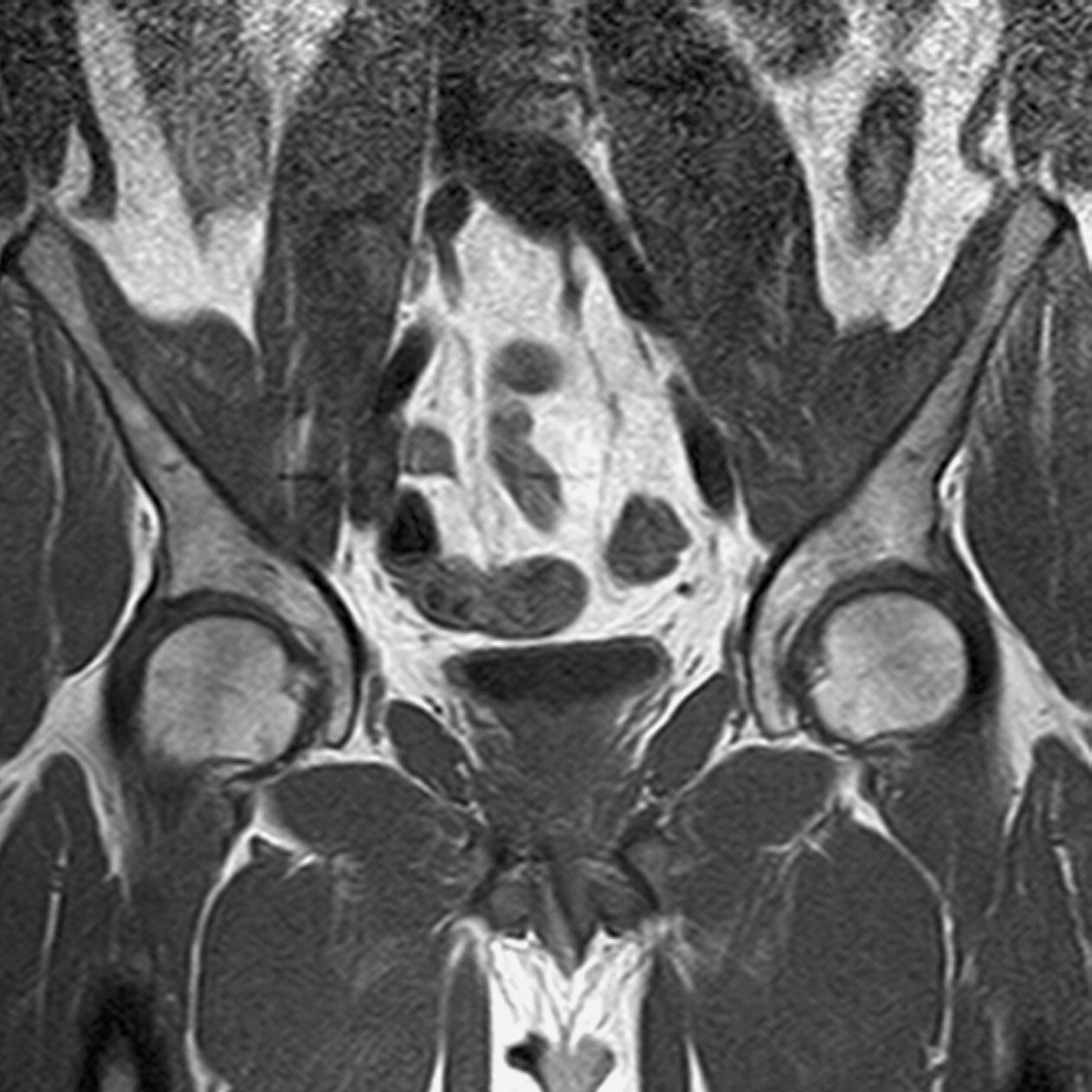
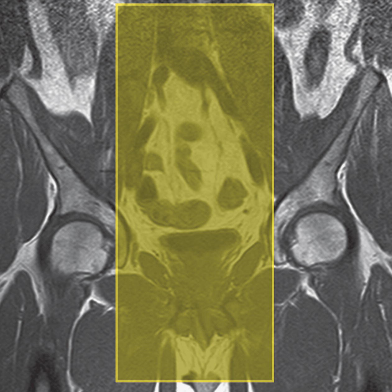
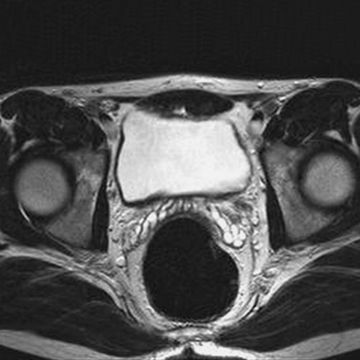
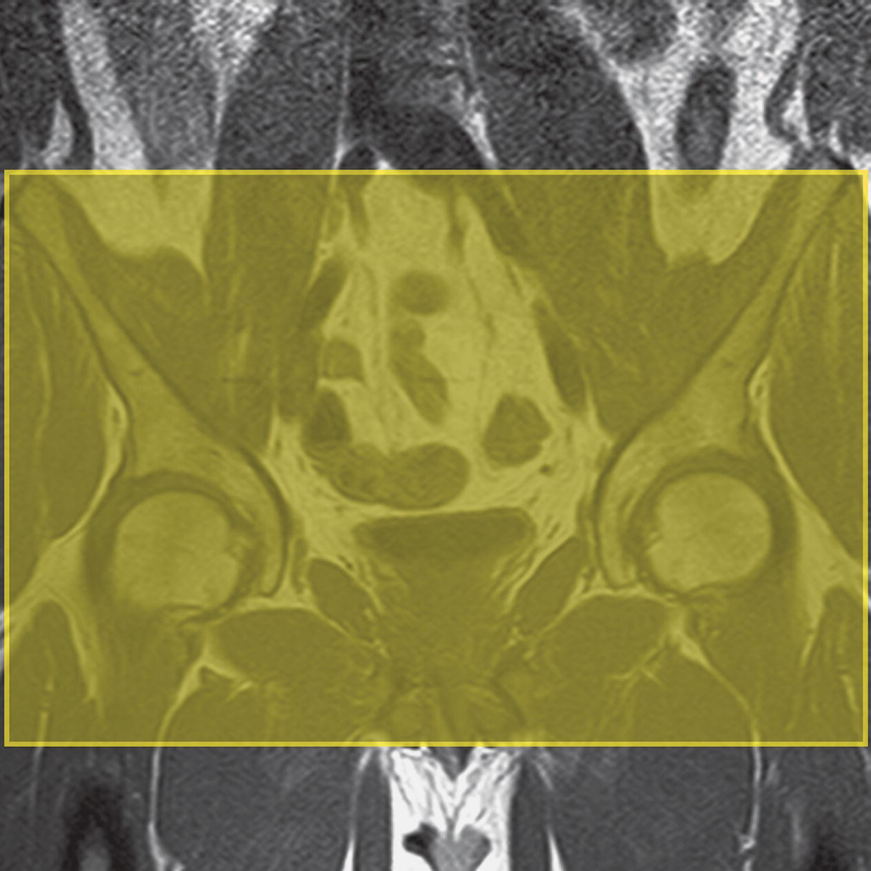
12 Table 12.1 Summary of parameters The figures given are for 1.5 T and 3 T systems. Parameters are dependent on field strength and may need adjustment for very low or very high field systems Figure 12.1 Sagittal section through the male pelvis showing midline structures. The patient lies supine on the examination couch. Foam pads and compression bands can be applied across the patient’s lower pelvis to reduce respiratory and bowel motion (unless the patient cannot tolerate this). The patient is positioned so that the longitudinal alignment light lies in the midline, and the horizontal alignment light passes through a point midway between the pubis symphysis and the iliac crests. If a local rectal coil is used, it should be carefully inserted prior to the examination. Ensure that it is correctly positioned and fully inflated. Figure 12.2 Coronal FSE T1-weighted image through the male pelvis. Acts as a localizer if three-plane localization is unavailable, or as a diagnostic sequence. Thick slices/gaps are prescribed from the coccyx to the anterior aspect of the pubis symphysis. The area from the pubis symphysis to the iliac crests is included in the image. P 60 mm to A 60 mm Sagittal localizers used in conjunction with a large FOV are useful to confirm the correct positioning of a rectal coil and to demonstrate nodes and bony metastases in patients with suspected prostatic carcinoma. L 25 mm to R 25 mm Demonstrates organs that lie in the midline (bladder, rectum, prostate, penis). Medium or thick slices/gaps are prescribed from the left to the right pelvic side walls (Figure 12.3). Unless lymph node involvement is suspected, small structures such as the prostate require high-resolution imaging using the rectal coil and thin slices/gap prescribed through the ROI only. Tissue suppression pulses are often necessary when using FSE sequences. Figure 12.3 Coronal FSE T1-weighted image through the male pelvis to show slice prescription boundaries and orientation for sagittal imaging. Figure 12.4 Axial FSE T2-weighted image through a normal male pelvis (rectal coil in situ). Demonstrates organs that lie laterally (lymph nodes). Medium or thick slices/gaps are prescribed from the pelvic floor to the iliac crests (Figure 12.5). Unless lymph node involvement is suspected, small structures such as the prostate require high-resolution imaging using the rectal coil and thin slices/gap prescribed through the ROI only. Tissue suppression pulses are often necessary when using FSE sequences.
Pelvis
1.5 T
3 T
SE
SE
Short TE
Min–30 ms
Short TE
Min–15 ms
Long TE
70 ms+
Long TE
70 ms+
Short TR
600–800 ms
Short TR
600–900 ms
Long TR
2000 ms+
Long TR
2000 ms+
FSE
FSE
Short TE
Min–20 ms
Short TE
Min–15 ms
Long TE
90 ms+
Long TE
90 ms+
Short TR
400–600 ms
Short TR
600–900 ms
Long TR
4000 ms+
Long TR
4000 ms+
Short TEL
2–6
Short TEL
2–6
Long ETL
16+
Long ETL
16+
IR T1
IR T1
Short TE
Min–20 ms
Short TE
Min–20 ms
Long TR
3000 ms+
Long TR
300 ms+
TI
200–600 ms
TI
Short or null time of tissue
Short ETL
2–6
Short ETL
2–6
STIR
STIR
Long TE
60 ms+
Long TE
60 ms+
Long TR
3000 ms+
Long TR
3000 ms+
Short TI
100–175 ms
Short TI
210 ms
Long ETL
16+
Long ETL
16+
FLAIR
FLAIR
Long TE
80 ms+
Long TE
80 ms+
Long TR
9000 ms+
Long TR
9000 ms + (TR at least 4 × TI)
Long TI
1700–2500 ms (depending on TR)
Long TI
1700–2500 ms (depending on TR)
Long ETL
16+
Long ETL
16+
Coherent GRE
Coherent GRE
Long TE
15 ms+
Long TE
15 ms+
Short TR
<50 ms
Short TR
<50 ms
Flip angle
20–50°
Flip angle
20–50°
Incoherent GRE
Incoherent GRE
Short TE
Minimum
Short TE
Minimum
Short TR
<50 ms
Short TR
<50 ms
Flip angle
20–50°
Flip angle
20–50°
Balanced GRE
Balanced GRE
TE
Minimum
TE
Minimum
TR
Minimum
TR
Minimum
Flip angle
>40°
Flip angle
>40°
SSFP
SSFP
TE
10–15 ms
TE
10–15 ms
TR
<50 ms
TR
<50 ms
Flip angle
20–40°
Flip angle
20–40°
1.5 T and 3 T
Slice thickness 2D
Slice thickness 3D
Thin
2–4 mm
Thin
<1 mm
Medium
5–6 mm
Thick
>3 mm
Thick
8 mm
FOV
Matrix
Small
<18 cm
Coarse
256 × 128/256 × 192
Medium
18–30 cm
Medium
256 × 256/512 × 256
Large
>30 cm
Fine
512 × 512
Very fine
>1024 × 1024
NEX/NSA
Slice number 3D
Short
1
Small
<32
Medium
2–3
Medium
64
Multiple
>4
Large
>128
PC-MRA 2D and 3D
TOF-MRA 2D
TE
Minimum
TE
Minimum
TR
25–33 ms
TR
28–45 ms
Flip angle
30°
Flip angle
40–60°
VENC venous
20–40 cm/s
VENC arterial
60 cm/s
TOF-MRA 3D
TE
Minimum
TR
25–50 ms
Flip angle
20–30°
Male pelvis
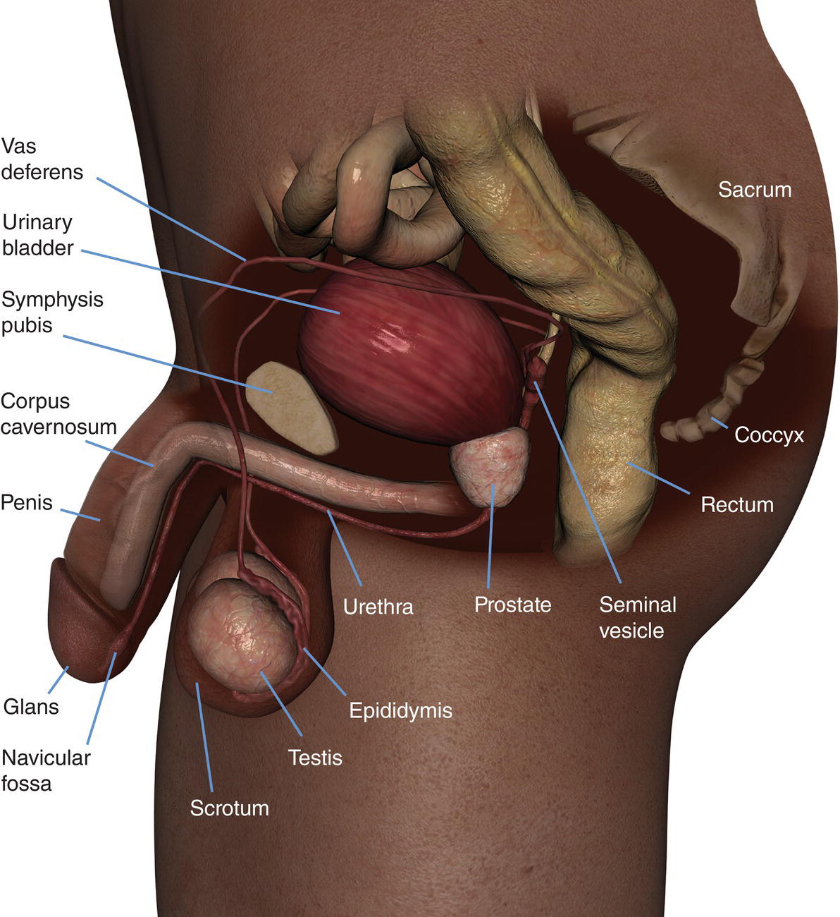
Basic anatomy (Figure 12.1)
Common indications
Equipment
Patient positioning
Suggested protocol
Coronal breath-hold fast incoherent (spoiled) GRE/SE/FSE T1 (Figure 12.2)
Sagittal SE/FSE T2
Axial SE/FSE T2 (Figure 12.4)
Related posts:
![]()
Stay updated, free articles. Join our Telegram channel


Full access? Get Clinical Tree


